There are roughly six different ways to joint pipework, and the right one depends on the material, location (above or below ground), application (water, heating, gas, drainage), and sometimes just what you've got in the van. Level 2 expects you to recognise each joint type from a picture, know what it's used for, and understand the specific rules around each — the lead-free solder rule, the manipulative-only-for-underground rule, the 10mm expansion gap on sanitary pushfit.
This post is the fourth in the Level 2 Plumbing Processes sub-cluster. For the others, see the hand tools, power tools, pipe materials, bending and installation posts.
WRAS approval — the starting point
All fittings used on hot or cold water installations should be approved by the Water Regulations Advisory Scheme (WRAS). WRAS maintains the Water Fittings and Materials Directory — a list of all approved fittings.
Why WRAS approval matters:
- Ensures fittings don't contaminate drinking water
- Confirms fittings meet pressure, temperature, and durability requirements
- Provides a traceable standard for installers and inspectors
You don't need to memorise specific WRAS-approved fittings; you need to know the principle — if it's going on a water system, it needs WRAS approval.
One rule that applies to every joint
All pipework must be deburred before any jointing procedure.
When you cut a pipe (by wheel cutter, pipe slice, or hacksaw), the cutting action leaves a sharp ridge of material on the pipe edge — internally and externally. This ridge:
- Restricts water flow if left inside the pipe
- Prevents fittings seating properly
- Can damage O-rings in pushfit fittings
- Leaves sharp edges that cut fingers
First action after cutting a pipe: de-burr both ends with the cutter. Not wash with soapy water, not apply flux, not clean with steel wool. Deburr first, then proceed.
Soldered joints — for copper
Soldering is the classic method for jointing copper pipework. Two main types:
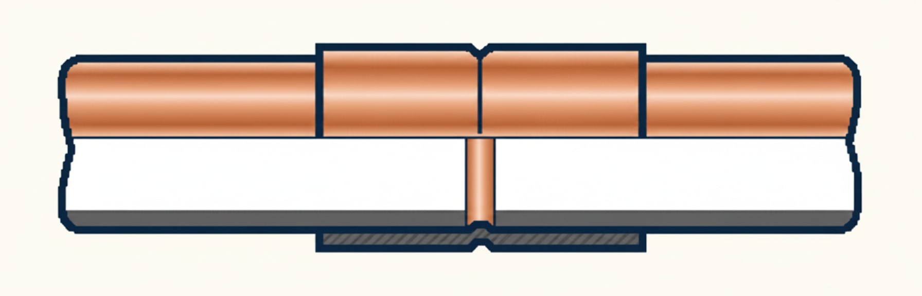
Integral solder ring fittings. A ring of lead-free solder is pre-built into the fitting. You don't need to add separate solder — heat the fitting and the ring melts, drawing solder through the joint by capillary action.
Endfeed fittings. No solder in the fitting — you add solder separately at the joint. The solder is drawn into the fitting through capillary action.
Both produce the same end result; integral ring is marginally cleaner and easier for beginners; endfeed is cheaper per fitting.
Lead-free solder only — on water systems
If a soldered fitting is fitted to a hot or cold water system, it must be fitted with lead-free solder.
Leaded solder was banned for potable water systems to prevent lead leaching into drinking water (covered in the cold water cluster's soft water discussion). On heating systems, leaded solder is sometimes still acceptable (the water isn't consumed) but modern practice uses lead-free throughout.
Never use leaded solder on cold water supply pipework — an exam trap that comes up reliably.
The soldering procedure — six steps
The workbook's specific soldering sequence. Each step matters; skipping any causes failures.
1. Cut and deburr the pipe. Clean straight cut, ends reamed smooth inside and out.
2. Clean the pipe and the fitting. Use wire wool or a fitting brush. Clean copper = clean metal surface = solder adheres. Copper pipes are cleaned to allow the solder to adhere to pipe surfaces — not to enable flux (C — flux does adhere to dirty copper, but solder won't), not for painting (B), not for corrosion prevention (D).
3. Apply a thin layer of flux to the pipe only. Use a brush — not your fingers, not by dipping. Flux is acidic and can damage skin. The flux prevents the copper oxidising when heated, allowing solder to flow properly.
Why apply flux with a brush: flux can damage skin (dermatitis risk — covered in H&S); also, brushing applies a thin even layer rather than a thick glob.
4. Add heat in the centre of the fitting. Heat until the flux bubbles or the flame changes colour — this tells you the copper is hot enough. If soldering near plastic clips or other heat-sensitive fittings, lay a damp cloth on the pipe to reduce heat transfer.
5. Add lead-free solder if required. Endfeed fittings need solder added; integral ring fittings don't (the ring melts when heated). Touch the solder to the joint edge — it should be drawn in by capillary action.
6. Clean the fitting with a damp cloth to remove excess flux. This prevents the flux corroding the pipe and leaving unsightly green staining.
Flux management — the green staining rule. Residual flux left on copper pipework will slowly corrode the pipe over time, leaving distinctive green verdigris staining. Always wipe excess flux off after the joint cools.
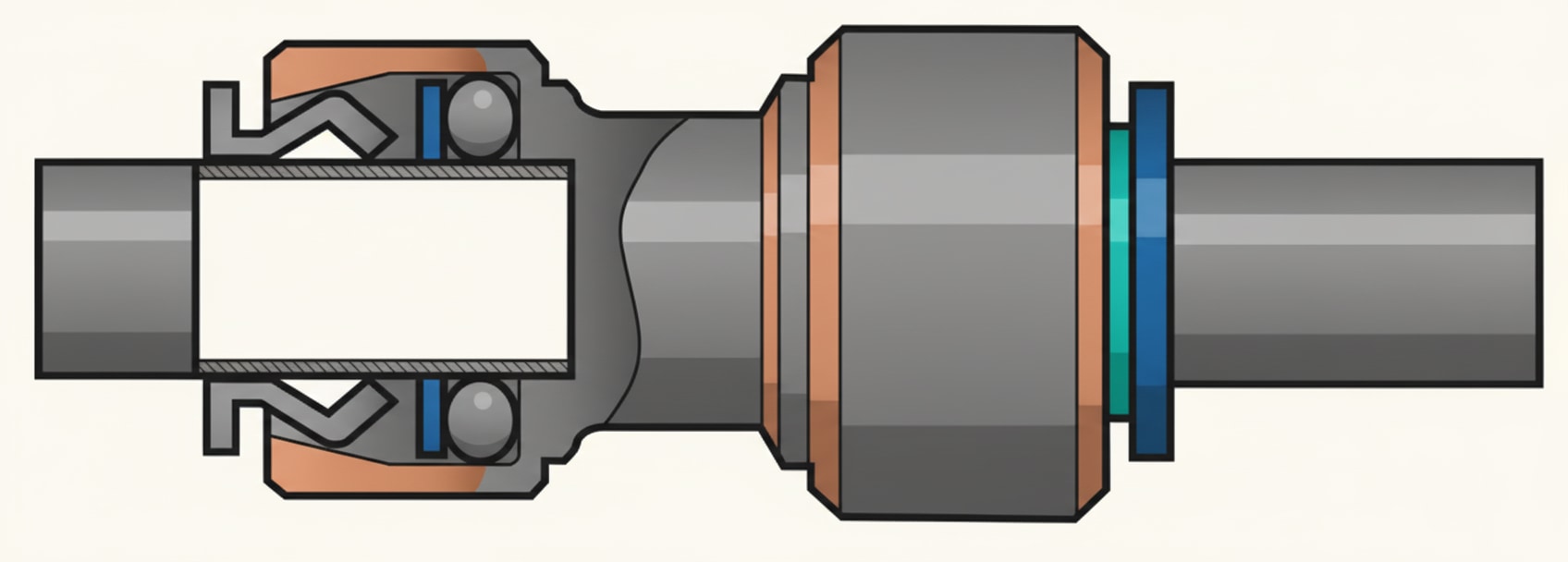
Pushfit fittings
Pushfit = push the pipe into the fitting and it's done. An internal grab ring holds the pipe; an O-ring seals.
What they work with:
- Copper (various manufacturers' systems)
- Polybutylene (PB)
Pushfit on waste/sanitary pipework (PVCu, ABS, MuPVC, PP) is a different category — covered below.
Advantages:
- Fast installation
- No heat required (safer in inaccessible areas, near flammables)
- Re-enterable (remove with a demounting tool and re-use)
Disadvantages:
- More expensive per fitting than soldered
- Generally higher profile (don't sit as close to the wall as solder joints)
- Some manufacturers' systems aren't fully inter-compatible
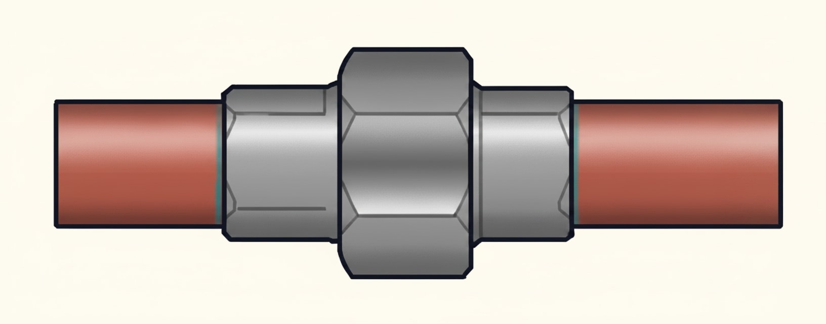
Compression fittings — Type A and Type B
Compression fittings use an olive (a soft metal ring) squeezed onto the pipe by tightening a nut against it. Two categories, with very different application rules.
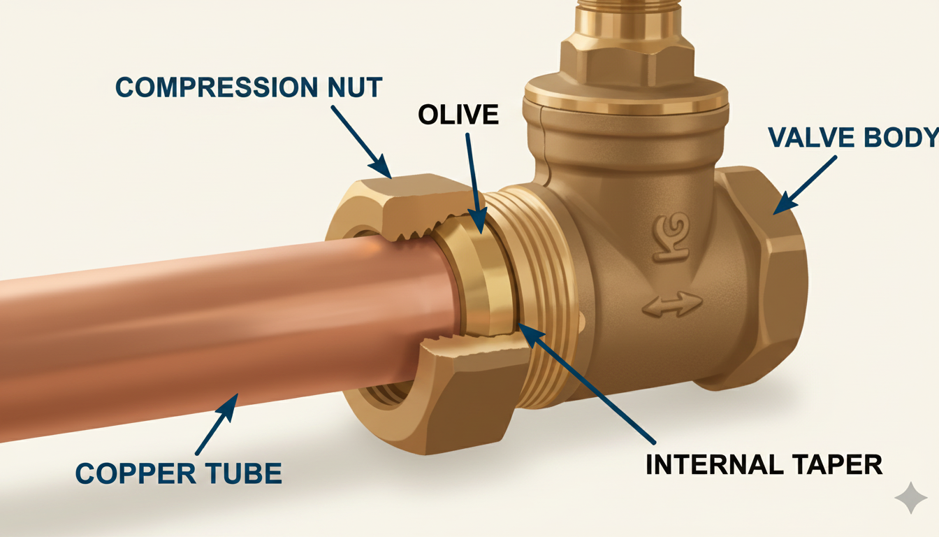
Non-manipulative compression (Type A).
The standard domestic compression fitting. The olive compresses onto the straight outside of the pipe.
- Used for copper, polybutylene, and polyethylene pipe
- Above ground only — cannot be used below ground
Why not underground? Ground movement can cause the pipe to pull out of the fitting under stress. Below-ground joints need something more robust.
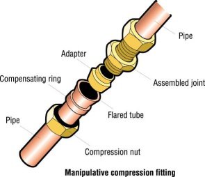
Manipulative compression (Type B).
The olive compresses onto a swaged (opened-out) end of the pipe. The swaged lip can't pull back through the olive, so the joint can't separate under stress.
- Used for R220 and R250 copper — cannot be used on R290 (hard copper can't be swaged)
- Above and below ground — suitable for underground water supply
The exam matching pattern:
| Joint type | Above ground | Below ground |
|---|---|---|
| Non-manipulative (Type A) | ✓ | ✗ |
| Manipulative (Type B) | ✓ | ✓ |
Copper pipe below ground = manipulative compression (Type B). Not non-manipulative (wrong below ground), not endfeed soldered (leaded solder banned on water; also soldering underground is impractical), not capillary soldered.
Polyethylene compression
Specifically for MDPE (polyethylene) pipework. Works above or below ground because the MDPE pipe is flexible rather than rigid — ground movement is absorbed by the pipe rather than transferring stress to the joint.
MDPE compression fittings always require a pipe insert (liner) — see below.
Best method for jointing MDPE underground cold water service pipework: pushfit compression fittings designed for polyethylene. Not capillary soldered (can't solder plastic), not end-feed solder (same), not solvent fittings (MDPE can't be solvent welded).
Pipe inserts — when soft pipes need support
Softer pipe materials need an internal insert (also called a liner or pipe stiffener) to support the pipe wall inside a compression fitting. Without the insert, tightening the compression nut crushes the pipe wall and the joint fails.
Materials that need pipe inserts:
- Polybutylene (PB)
- Polyethylene (MDPE)
- Large-bore R220 copper (soft grade can deform under compression)
Why the insert is needed: the insert is a rigid sleeve that sits inside the pipe end, giving the compression mechanism something solid to compress against. Without it, the pipe wall squashes inward rather than being sealed by the olive.
The specific role is described on exam papers as: supporting the pipe wall against the fitting inside the joint.
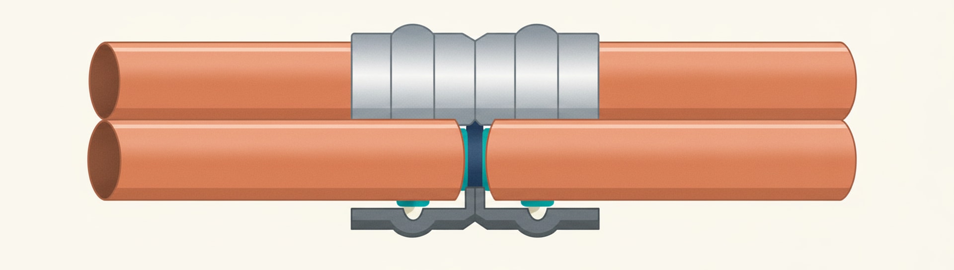
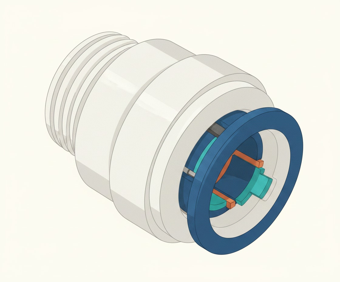
Press-fit fittings
A newer jointing method. Press-fit fittings look similar to integral solder ring fittings but contain a rubber O-ring that's compressed onto the pipe by a crimping machine.
Advantages:
- No heat — safer than soldering in loft spaces, near flammables, near plastic pipework
- Fast once the crimp tool is set up
- Strong, reliable joint
- Particularly common in commercial installations
Disadvantages:
- Expensive crimp tool required
- Press-fit fittings are more expensive per joint
- Not re-enterable (one-time crimp)
The crimping machine is a battery-powered or mains tool (covered in the power tools post).
Threaded joints — for LCS
Low Carbon Steel (LCS) uses threaded joints as the standard method. Two ways:
Threaded fittings (most common). The thread is cut into the pipe using stocks and dies, then a fitting with a matching female thread is screwed on. The joint is made watertight by adding a jointing compound:
- PTFE tape — for cold or hot water
- Boss White (or Hawk White) — for heating systems
Compression fittings for LCS. Quicker and easier to install, but considerably more expensive per joint. Used where threading isn't practical.
Thread cutting direction: when manually threading steel pipe, the cutting action must be reversed at the end of the cut to release swarf from the cutting head. Not to cool the teeth (A), not to let the pipe flex (B), not to activate lubricant (D).
LCS can NOT be jointed by capillary (solder ring) or bronze welded joints as standard domestic practice — the workbook lists threaded joints as the standard method for LCS. ("Bronze welded joints" appears as a distractor option in exam questions; it's a specialist technique, not typical Level 2 practice.)
Galvanised steel pipe on cold water installations uses hemp and paste as a traditional jointing method (though modern installations typically don't use galvanised steel for water supply).
Leadwork and lead-to-copper connection
Historically, lead was used extensively for water pipework. Modern work involves replacing lead with copper or MDPE — but you may need to connect new copper to existing lead.
Lead pipe can be connected to a copper supply pipe using joint wiping — a traditional technique where molten solder is applied and wiped smooth. This is a specialised skill that few modern plumbers still practice.
Leadlock / proprietary fittings — modern alternatives to joint wiping. Compression-style fittings designed specifically for lead-to-copper transitions, available from specialist manufacturers.
Sanitary pipework joints
The plastic drainage pipe (PVCu, ABS, MuPVC, PP) in waste and soil systems uses three jointing methods:
Compression (sanitary). Pipe inserted through a rubber seal; nut tightened. Quick; allows disassembly for servicing.
Ring seal / pushfit. Pipe pushed through an O-ring seal. Most common method for sanitary plastics.
Preparation for sanitary pushfit (three things to do before inserting):
1. Chamfer the pipe end
2. Deburr the cut edge
3. Apply silicone-based lubricant to help the pipe past the O-ring
Solvent weld. The pipe and fitting are cleaned with solvent cleaner, dry-assembled to mark the angle, dismantled, coated in solvent cement, and reassembled with a slight twist. The twist spreads the cement and ensures a water- and air-tight joint.
Polypropylene (PP) cannot be solvent welded. Use pushfit or compression only. This is a reliably-tested Level 2 exam fact.
The 10mm expansion gap (sanitary pushfit)
Plastic sanitary pipe expands and contracts significantly with temperature changes. To accommodate this, pushfit sanitary fittings are fitted with a 10mm gap between the end of the pipe and the shoulder of the fitting socket.
Why 10mm: this gap lets the pipe expand into the fitting when it heats up (from hot water flowing through) without creating pressure on the fitting. Without the gap, expansion forces the fitting apart and the joint fails.
When jointing sanitary pushfit, leave 10mm between the end of the pipe and the fitting shoulder. Not "for ease of removal," not "for corrosion clearance," not "for the X dimension" — specifically for thermal movement.
At low temperatures, plastic sanitary pipework becomes more brittle — extra care needed when working with it in cold conditions.
Flux application — by brush only
The correct method for applying flux to copper pipe is by brush. Not using fingers (flux damages skin). Not dipping the pipe in flux (wastes flux and creates mess). Not applying with steel wool (contaminates the wool).
A small stiff brush (often supplied with flux containers) lets you apply a thin even layer just where needed, keeping flux off your hands and off parts of the pipe that don't need it.
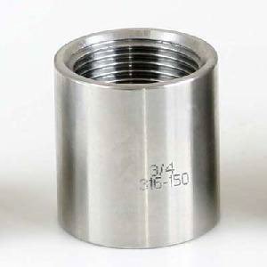
Fitting shapes — the six categories
Regardless of which jointing method you're using, the shape of the fitting falls into six categories:
Coupling (straight coupler). Straight connection between two pipes of the same size. Simple connector.
Elbow. Changes direction of the pipework. Sub-types:
- Knuckle 90° elbow — tight 90° bend with a short radius
- Swept 90° elbow — longer-radius 90° bend (smoother flow, less pressure loss)
- 45° elbow — 45° bend
- Street elbow (m/f elbow) — 90° or 45° bend with one male end and one female end
Stop end. Closes an open end of pipework. Used when running a pipe to a temporary or future connection point.
Reducer. Reduces pipe size (e.g., 28mm to 15mm). Available as straight or bent reducers, and as reducing tees.
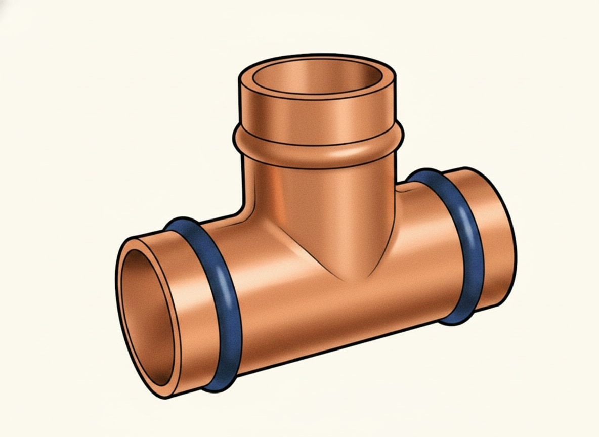
Tee. Three-way fitting. Two main types:
- Equal tee — all three legs the same size
- Reducing tee — one or more legs a smaller size than the others
Tee naming convention: always state the middle (branch) leg last. A tee with 28mm on both straight ends and 35mm on the branch is a 28-28-35 tee. A tee with 22mm on both straight ends and 15mm on the branch is a 22-22-15 tee. A tee with 22mm on one straight end, 15mm on the branch, and 22mm on the other straight end is 22-15-22.
Different order = different fitting. Getting this convention right prevents ordering mistakes.
X dimensions
The X dimension is the distance from where a pipe stops inside a fitting to the centre line of the fitting.
Why X dimensions matter: when planning pipework, we normally measure from the centre of one fitting to the centre of the next. But we cut pipe between the fittings, not through them. The X dimension lets us convert centre-to-centre measurements into actual pipe cut lengths.
The formula: Pipe cut length = centre-to-centre distance − X dimension of first fitting − X dimension of second fitting.
Worked example 1: if the total centre-to-centre distance between two fittings is 200mm, and the X dimension of each tee is 15mm:
Cut length = 200 − 15 − 15 = 170mm
Worked example 2: if the centre-to-centre distance is 320mm, the X dimension of the tee on one side is 12mm, and the X dimension of the elbow on the other side is 8mm:
Cut length = 320 − 12 − 8 = 300mm
Why this matters in practice: cutting pipes to the centre-to-centre dimension gives pipes that are too long to fit. Subtracting the X dimensions gives the actual length needed. Getting it right means pipes fit first time; getting it wrong means re-cutting and wasted material.
Common exam traps
Trap 1: Lead-free solder only on water systems. Never leaded solder on hot or cold water.
Trap 2: Clean copper = solder adheres. The reason for cleaning. Not for flux adherence, not for painting.
Trap 3: Flux applied with a brush. Not fingers, not by dipping, not steel wool.
Trap 4: First action after cutting = deburr. Not wash, not flux, not clean with wool.
Trap 5: Non-manipulative compression = above ground only. Manipulative = above or below ground.
Trap 6: R290 cannot be used with manipulative compression — can't be swaged.
Trap 7: MDPE underground = polyethylene compression (pushfit type). Not soldered, not solvent.
Trap 8: Polypropylene cannot be solvent welded. Pushfit or compression only.
Trap 9: Sanitary pushfit needs 10mm expansion gap for thermal movement.
Trap 10: Pipe inserts for PB, PE, large R220 copper. Support pipe wall.
Trap 11: Tee naming convention — middle (branch) leg last. 28-28-35 (straight ends first, branch last).
Trap 12: X dimension = pipe stop to fitting centre line. Subtract from centre-to-centre distance to get cut length.
Trap 13: LCS jointing = threaded (PTFE water / Boss White heating).
Trap 14: Threading LCS — reverse at end to release swarf.
Trap 15: Lead-to-copper connection = joint wiping (traditional) or proprietary leadlock fitting (modern).
Quick revision summary
Before the mock test, eight things you need to be able to produce from memory:
- WRAS approval required for all water fittings; all pipework deburred before jointing
- Soldering sequence: cut/deburr → clean → flux (brush only) → heat → solder (lead-free on water) → clean off flux
- Compression Type A (non-manipulative) = above ground only; Type B (manipulative) = above or below (R220/R250 only, not R290)
- Pushfit = copper and PB; pipe inserts needed for PB, PE, large R220 copper
- Press-fit = O-ring + crimping machine; no heat
- LCS = threaded (PTFE water / Boss White heating); threading reversed to release swarf
- Sanitary pushfit: 10mm expansion gap; PP cannot be solvent welded
- Fitting shapes: coupling / elbow / stop end / reducer / tee (middle last: 22-22-15)
- X dimension = pipe stop to fitting centre; subtract from centre-to-centre for cut length
📝 10-Question Mock Test
Click an option to see whether you got it right. Explanations appear instantly — no submitting at the end.
Deburring is always the first action after cutting. The burr inside the pipe restricts flow and prevents proper seating of fittings. Washing (C), flux (B), and steel wool (A) all come later — or not at all for plastic joints.
A brush gives a controlled thin layer without skin contact. Fingers (A) cause dermatitis risk. Dipping (B) wastes flux. Steel wool (D) contaminates the wool.
Clean copper lets the molten solder wet the surface properly. Flux (C) actually does adhere to dirty copper — the cleaning is for solder. Painting (B) and corrosion (D) aren't the reason.
The swaged pipe end prevents separation under ground movement stress. Non-manipulative (A) is above ground only. Leaded solder (C) is banned on water supply. Lead-wiped (D) is for lead-to-copper transitions, not copper-to-copper.
Leaded solder is banned on cold water supply pipework to prevent lead contamination of drinking water. Options A, B and D are all acceptable for cold water: pushfit with PB, endfeed with lead-free solder, and manipulative compression.
The standard MDPE underground jointing method. MDPE can't be soldered (A, C — can't solder plastic) and can't be solvent welded (D — MDPE is a polyethylene, not a solvent-welded plastic).
Supports the soft pipe wall from inside so the olive compresses effectively. Captive nut (A) is part of the fitting body. Olive (C) is the compression ring itself. Longscrew (D) is a different fitting type (used on LCS).
Plastic sanitary pipework expands significantly when hot water flows through. The 10mm gap accommodates this expansion. Options A (X dimension), C (corrosion — plastic doesn't corrode in the same way) and D (removal — not the purpose) don't describe the expansion gap function.
PP can only be jointed with pushfit or compression. PVCu (A), ABS (C) and MuPVC (D) all accept solvent welding.
Reversing the die backs the swarf out of the cutting teeth so they don't clog. Not cooling (A), not flexing (B), not lubrication (D).
How PlumbMate puts this into practice
Jointing content is heavy on matching joint type to pipe material and application — exactly the kind of content spaced repetition handles best.
- Flashcards, not essays. One prompt, one answer — the format that research has consistently shown works best for active recall.
- Wrong answers are logged. Every question you get wrong goes into a dedicated collection that resurfaces more frequently in future sessions.
- The 3× rule. You need to get a question right three times before it clears — one lucky guess isn't enough.
- Explanations on every question. Like the ones above, but on every single question in the app.