Every central heating system you'll ever work on handles water expansion in one of two ways: a feed and expansion cistern open to atmosphere (open-vented), or a sealed system with an expansion vessel (sealed). The distinction matters because everything else — how the system fills, how it vents, where the pump goes — depends on which type it is. Get this straight and an entire family of exam questions falls into place.
This is the fifth post in the Level 2 heating sub-cluster. For the others, see the system types, boilers, controls, system layouts, and commissioning posts.
The core difference
When water heats up it expands — about 4% from cold to near-boiling. A heating system has to give that extra water somewhere to go, otherwise the pressure inside climbs until something fails. Two different solutions:
- Open-vented systems are open to the atmosphere. A feed and expansion (F&E) cistern sits above the system, and water expanding during heating rises into the cistern through the cold feed. No pressure build-up because the system is always at atmospheric pressure.
- Sealed systems are sealed from the atmosphere. An expansion vessel — a sealed vessel with a rubber diaphragm and a pressurised air cushion — absorbs the volume change. The system runs at a higher pressure than atmospheric, typically around 1 bar cold and 2 bar hot.
Both approaches work. Each has its own component requirements, pipework, and installation rules.
Open-vented systems: the components
Feed and expansion (F&E) cistern
The cistern that fills the heating system and accepts the expansion water.
Key facts:
- Fitted at the highest point of the system — usually in the attic — because it feeds the system by gravity
- Minimum actual capacity of 18 litres for small domestic systems
- On larger systems, should be sized to take up to 4% of the system volume
- The water level must be set well below the overflow to allow room for the expansion water coming up from the heating circuit
- A plastic F&E cistern must sit on a firm, level board 150mm longer and wider than its base — not directly on ceiling joists (which would be uneven and could crack the plastic)
Cold feed
The pipe from the F&E cistern into the primary heating circuit.
Key facts:
- Minimum 15mm
- No valves must be fitted on it — ever. The cold feed needs to be always open, both for filling and for the expansion water to return to the F&E cistern under normal running
Under normal conditions, when the water heats up, it expands back into the cistern through the cold feed. Under fault conditions, the expansion water goes up the open vent pipe instead — which is why we need both pipes.
Open vent pipe
The safety pipe that lets steam or overheated water escape to atmosphere if the system overheats.
Key facts:
- Comes off the flow pipe close to the boiler, and rises above the F&E cistern
- Minimum 22mm (19mm internal diameter)
- Must rise 450mm minimum above the water level in the F&E cistern
- The 450mm rise prevents "pumping over" — water being pushed up and out of the vent when the pump starts, caused by the surge effect
- No valves allowed on the open vent — same reason as the cold feed, it must never be blocked
If a fault causes the system to overheat, the expansion water (or steam) goes up the vent and discharges into the F&E cistern. The vent is the safety relief for an open-vented system.
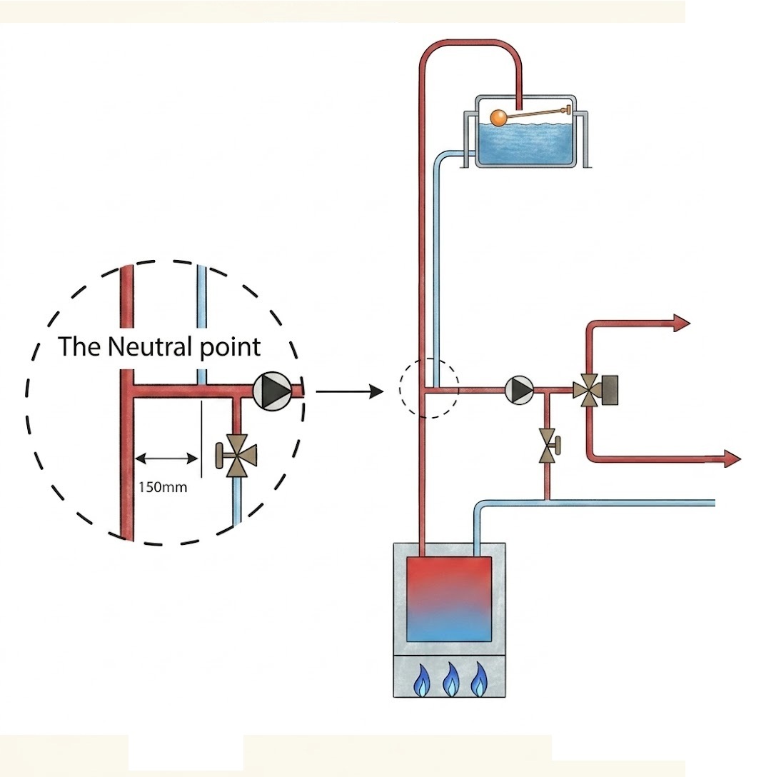
The neutral point
A central concept in open-vented systems. The "neutral point" is where the cold feed and open vent connect to the primary circuit — it's the point at atmospheric pressure regardless of what the pump is doing.
Key facts:
- The neutral point is formed where the cold feed enters the system (and where the open vent leaves it)
- The pump must be positioned so the system runs mostly under positive pressure — usually with the pump on the flow, downstream of the neutral point
- Positive pressure is preferred because (1) the pump is more efficient pushing than pulling, and (2) positive pressure prevents air being drawn into the system through any small leaks
Close coupling
The cold feed and open vent should enter the system within 150mm of each other — this is called "close coupling" and it prevents problems caused by pressure differences between the two connection points.
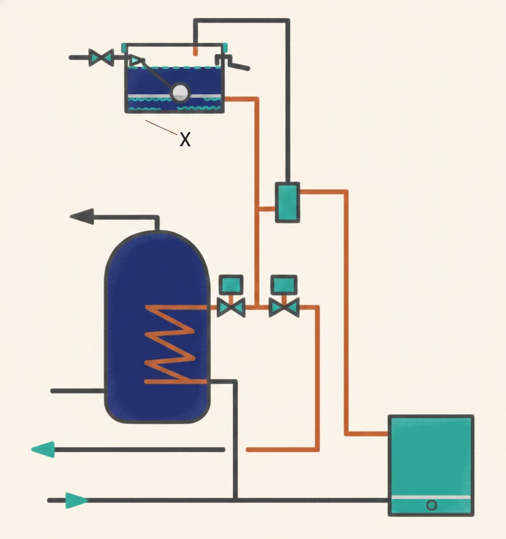
An air separator is often used to achieve close coupling. The air separator has dedicated ports for the vent, the cold feed, and the flow pipework, allowing all the connections to be brought together neatly while also helping remove air from the system.
Port arrangement on an air separator:
- Vent comes off the top
- Flow from the boiler enters the second-highest port
- Flow to the pump leaves the lower connection on the same side as the flow-in
- Cold feed connects opposite the flow-out
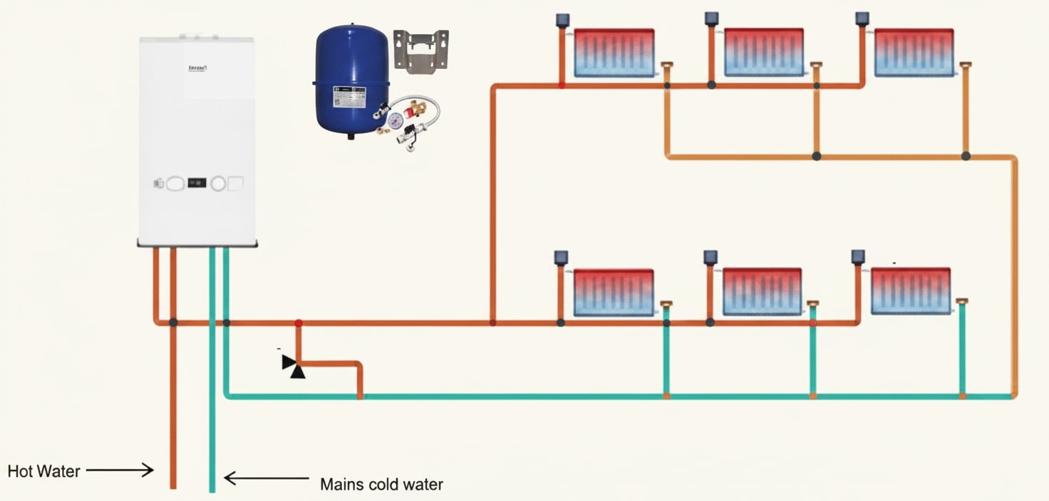
Sealed systems: the components
Filling loop
Sealed systems don't have an F&E cistern — they're filled directly from the cold water mains through a filling loop.
Key facts:
- Flexible, removable connection between the cold supply and the heating return
- Protected from backflow through a double check valve — essential to prevent dirty heating water contaminating the mains
- Once the system is filled, the filling loop should be disconnected — it's a temporary connection, not a permanent plumbing fixture
Expansion vessel
The component that absorbs water expansion in a sealed system.
How it works:
- A sealed vessel with a rubber diaphragm inside
- One side of the diaphragm is pressurised with air (usually nitrogen)
- As the water expands, it pushes against the diaphragm, compressing the air
- When the water cools and contracts, the air cushion pushes back, returning water to the system
Installation rules:
- Fitted on the coolest part of the circuit — normally the return pipe close to the boiler — because heat damages the rubber diaphragm over time
- Combi boilers have an expansion vessel built in, so an external one isn't needed
- System boilers also have one built in, often positioned internally
The expansion vessel is the neutral point on sealed systems (equivalent to the cold feed/vent junction on open-vented). The pump should ideally be positioned just after the expansion vessel.
Pressure relief valve (temperature/pressure relief valve)
If the sealed system overheats or becomes over-pressurised, there must be a temperature pressure relief valve fitted — also called a T&P relief valve.
Key facts:
- Fitted on the boiler itself
- Discharges to a safe position outside
- The discharge pipe must fall continuously to the discharge point
- Must not discharge too close to ground level (mud or stones could block it)
- If discharging below head height, the pipe should be turned back to the wall and protected by a cage to prevent scalding injury to people nearby
- Minimum 15mm discharge pipe on a small boiler
This is the sealed-system equivalent of the open vent pipe — the ultimate safety relief for over-pressure or over-temperature.
Air release
Air in a sealed system is released through air release valves — either manual or automatic.
Key facts:
- Installed at high points of the system, or anywhere there's likely to be an airlock (e.g. where pipework rises then drops again)
- Automatic air release valves have a float — as the system fills with water, the float rises and seals. If air builds up, the float drops and lets the air out
- Air release valves can be used on both sealed and open-vented systems
Pump position
On a sealed system the pump is normally positioned on the flow, just after the expansion vessel (the neutral point). In combi boilers the pump is built in; in system boilers it's often positioned in the cylinder cupboard close to the motorised zone valves.
Side-by-side comparison
| Feature | Open-vented | Sealed |
|---|---|---|
| Air release | Open vent pipe, F&E cistern, manual/auto air valves | Auto or manual air release valves only |
| Expansion (normal) | Water rises into F&E cistern through cold feed | Absorbed by expansion vessel diaphragm |
| Expansion (overheat/fault) | Discharges through open vent into F&E cistern | Discharged through T&P relief valve |
| Filling | From F&E cistern (gravity) | Filling loop from cold mains (disconnected after filling) |
| Pump position | On flow, downstream of neutral point (cold feed/vent junction) | On flow, just after expansion vessel (neutral point) |
| Pressure | Atmospheric (no pressure build-up) | Pressurised (~1 bar cold, ~2 bar hot) |
Common exam traps
Trap 1: Valves on the cold feed or open vent. NEVER fit valves on either. Both need to stay permanently open for filling and for safety relief.
Trap 2: Open vent rise. The open vent must rise 450mm minimum above the F&E water level to prevent pumping over. A common distractor is 150mm or 300mm.
Trap 3: F&E cistern support. Plastic F&E cisterns sit on a firm, level board 150mm longer and wider than the base — not directly on joists. This comes up as a multiple-choice question reliably.
Trap 4: Expansion vessel position. Fit it on the coolest part of the circuit — usually the return near the boiler. Heat damages the rubber diaphragm, so putting it on a hot part of the system shortens its life.
Trap 5: Neutral point location. Open-vented neutral point = where cold feed and open vent meet the primary circuit. Sealed system neutral point = expansion vessel. Both define where the pump is positioned.
Trap 6: T&P discharge. Must fall continuously to outside, not too close to the ground, protected if below head height. A pipe that rises in any part would trap water and fail to discharge properly.
Quick revision summary
Before the mock test, seven things you need to be able to produce from memory:
- Open-vented: F&E cistern, open vent pipe (22mm min, 450mm rise), cold feed (15mm min), no valves on either safety pipe
- F&E cistern: min 18L capacity, or 4% of system volume; plastic sits on board 150mm larger than base
- Sealed: filling loop with double check valve (disconnected after filling), expansion vessel, T&P relief valve on boiler
- Expansion vessel: rubber diaphragm, fitted on coolest part of circuit (return near boiler)
- Neutral point: open-vented = at cold feed/vent junction; sealed = at expansion vessel
- Pump: positioned to run system under positive pressure; just downstream of neutral point
- T&P discharge: continuous fall to safe position outside, minimum 15mm, not below head height without cage
📝 10-Question Mock Test
Click an option to see whether you got it right. Explanations appear instantly — no submitting at the end.
Minimum 22mm (with 19mm internal diameter). The open vent must be big enough to release overheated water or steam quickly under fault conditions. Options A and B are undersized; option D is over-specified.
The vent must rise at least 450mm above the water level to prevent pumping over — water being pushed up and out of the vent when the pump starts, caused by the surge effect. Shorter rises (150mm or 300mm) wouldn't prevent this and the system would spit water into the cistern every time the pump cycled.
Minimum 18 litres actual capacity for a small system. Larger systems need more (up to 4% of system volume). Option A is too small; options C and D would be for much larger systems.
Plastic cisterns need continuous level support — placing them directly on joists could flex or crack the plastic as it fills with water. The board provides even support across the whole base.
Water expands about 4% in volume from cold (4°C) to near boiling (100°C). The F&E cistern has to be sized to receive this expansion water — otherwise the cistern overflows every time the system heats up.
The filling loop is a flexible, removable connection between the cold mains and the heating return, protected by a double check valve. The other options don't fit: F&E cisterns are for open-vented systems, cold water storage cisterns supply outlets not heating circuits, and the expansion vessel absorbs expansion rather than filling the system.
The defining feature of a sealed system. F&E cisterns and open vent pipes are open-vented components. A pressure reducing valve isn't a standard part of a sealed heating system either — sealed systems run at a fixed higher pressure without needing reduction.
Heat damages the rubber diaphragm over time, so placing the vessel on the return (where the water has already given up most of its heat) protects it and extends its life. Option A would cook the diaphragm; the other options are irrelevant to a sealed system.
The open vent connects the system to atmosphere through the F&E cistern, so pressure stays at atmospheric. It also provides a fault-condition route for over-heated water or steam to escape. Option A describes the cold feed's job; options B and C are unrelated to the vent.
On a sealed system, the expansion vessel is the point of atmospheric reference — the place where pressure is determined by the air cushion, not by pump activity. The pump is positioned just downstream of it so the rest of the system runs under positive pressure.
How PlumbMate puts this into practice
Open-vented vs sealed is fact-heavy and examiner-favourite content — dozens of specific values and positions that need to be at your fingertips. Spaced repetition clears these far faster than re-reading.
- Flashcards, not essays. One prompt, one answer — the format that research has consistently shown works best for active recall.
- Wrong answers are logged. Every question you get wrong goes into a dedicated collection that resurfaces more frequently in future sessions.
- The 3× rule. You need to get a question right three times before it clears — one lucky guess isn't enough.
- Explanations on every question. Like the ones above, but on every single question in the app.