Once pipe is cut, jointed, and bent to shape, it needs fixing to the building. Clip it wrong, and it sags, noisily expands and contracts, or damages the structure. Notch a joist incorrectly, and you weaken the floor. Chase a wall too deeply, and you compromise the building structurally. Level 2 tests the specific clip spacing figures, the joist notching/drilling calculations, and wall-chasing limits — these are reliably tested facts and memorising them cold is the fastest way to score marks.
This post is the sixth and final deep-dive in the Level 2 Plumbing Processes sub-cluster. For the others, see the hand tools, power tools, pipe materials, jointing and bending posts.
Building Regulations Part A — structural safety
Part A of the Building Regulations deals with structural strength. Notching, drilling, and chasing all affect the structural integrity of the building — so all three are covered by Part A.
Why this matters: if you weaken a joist by over-notching it, the floor above can sag or collapse. If you chase a wall too deeply, particularly horizontally, the wall can lose load-bearing capacity. The rules that follow aren't arbitrary — they're calculated to keep structural strength above safety thresholds.
Part B — fire safety — has its own application to plumbing work and is covered later in this post under Pipe penetrations through fire-rated walls.
Other Building Regulations parts mentioned in other clusters:
- Part G — sanitation, hot water safety, water efficiency (covered in hot water and cold water clusters)
- Part L — conservation of fuel and power (insulation; covered in hot water cluster)
- Part P — electrical safety (covered in electrical cluster)
Notching and drilling joists — the foundations
Joists are the timber (occasionally metal) beams that support floorboards above and ceilings below. Plumbers run pipework through joists by either:
- Notching — cutting a small rectangular chunk out of the top of the joist
- Drilling — boring a round hole through the depth of the joist
Both weaken the joist, so both have strict rules about where and how much.
Minimum joist depth — 100mm
Before notching or drilling, measure the joist and check it is at least 100mm in depth.
Why: joists shallower than 100mm don't have enough structural mass to survive any significant notching or drilling. If the joist is less than 100mm deep, don't cut or drill it — find another route for the pipe.
The notching and drilling zones
You can only notch or drill within specific zones of the joist span, calculated from the distance between the supporting walls.
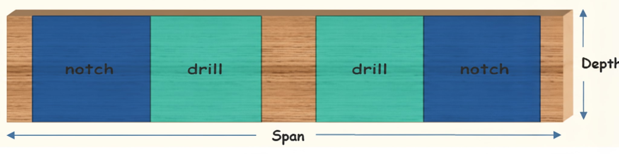
Joist terminology:
- Span = the distance between one supporting wall and the next
- Depth = the height of the joist from top to bottom
All the calculations that follow use these two measurements.
Notching calculations
Three notching rules:
| Rule | Calculation |
|---|---|
| Closest to supporting wall you can notch | 0.07 × span |
| Farthest from supporting wall you can notch | Span ÷ 4 |
| Maximum depth of notch | Depth ÷ 8 |
Worked example — a 4-metre span, 200mm deep joist:
- Closest to wall: 0.07 × 4000mm = 280mm (no notching within 280mm of the wall)
- Farthest from wall: 4000mm ÷ 4 = 1000mm (no notching beyond 1000mm from the wall)
- Maximum notch depth: 200mm ÷ 8 = 25mm (notch no deeper than 25mm)
So on a 4m span joist, notching is allowed only in the zone between 280mm and 1000mm from either end, and no deeper than 25mm.
Exam question type: "What is the maximum depth of notch in a 250mm joist?" → 250 ÷ 8 = 31.25mm ≈ 31mm.
Drilling calculations
Drilling rules are slightly different from notching — drilled holes are in the middle of the joist rather than at the top, so the structural impact is different.
Four drilling rules:
| Rule | Calculation |
|---|---|
| Closest to supporting wall you can drill | Span ÷ 4 |
| Farthest from supporting wall you can drill | 0.4 × span |
| Maximum diameter of drill hole | Depth ÷ 4 |
| Closest you can drill one hole to another | 3 × diameter of largest hole |
Worked example — the same 4-metre span, 200mm deep joist:
- Closest to wall: 4000mm ÷ 4 = 1000mm
- Farthest from wall: 0.4 × 4000mm = 1600mm
- Maximum hole diameter: 200mm ÷ 4 = 50mm
- Spacing between holes: 3 × 50mm = 150mm (between the centres or edges of adjacent holes)
Drilling zone = 1000mm to 1600mm from either end; max hole diameter 50mm; min 150mm spacing between holes.
Exam question type: "What is the largest hole that can be drilled in a timber joist?" → Depth ÷ 4.
Exam question type: "What is the maximum diameter of hole that can be drilled in a first floor joist that is 220mm deep?" → 220 ÷ 4 = 55mm.
Exam question type: "What is the minimum distance apart that two holes should be drilled in a timber joist?" → 3 diameters (of the largest hole).
Chasing walls
Running pipework inside walls requires cutting a channel ("chasing") into the wall surface. Like joist work, this weakens the wall, so limits apply.
Chasing rules:
| Direction | Maximum depth |
|---|---|
| Horizontal chase | ⅙ (one-sixth) of the wall thickness |
| Vertical chase | ⅓ (one-third) of the wall thickness |
Why vertical chases can go deeper: vertical chases interrupt less of the wall's load path — the wall still bears load through the full-thickness sections on either side. Horizontal chases cut across load lines and have a greater structural impact, so the depth limit is more restrictive.
Worked example — a 100mm wall:
- Maximum horizontal chase depth: 100 ÷ 6 = ~17mm
- Maximum vertical chase depth: 100 ÷ 3 = ~33mm
Exam question type: "When chasing out walls for pipework installations, the depth of any horizontal wall chased should be no deeper than..." → ⅙ the wall thickness.
Pipe penetrations through fire-rated walls — Part B
Part B of the Building Regulations covers fire safety. One specific application affects plumbing work directly: when pipework passes through a fire-rated wall or any floor, the penetration creates a potential route for fire and smoke to spread between compartments. Without a barrier in that gap, a fire on one floor could travel up the soil stack to the next.
The solution is an intumescent collar — known on site as a fire collar. It's a metal-cased collar containing intumescent material, fitted around the pipe at the penetration point.
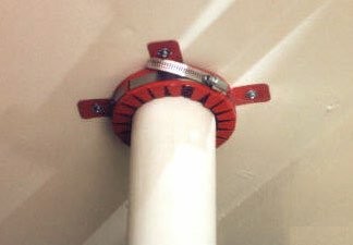
How it works: the intumescent material is inert at normal temperatures, but when heated by a fire it swells rapidly — many times its original volume — crushing the plastic pipe inwards and sealing the opening. The collar effectively replaces the soft plastic pipe with a solid plug, blocking flames and smoke from passing through.
When they're required: where a sanitary pipe (a soil stack or branch pipe) passes through a fire wall or any floor. Plastic pipes need this protection because plastic melts and burns; metal pipes (cast iron stacks) don't deform in a fire in the same way, though the penetration still needs to be properly sealed.
Common exam angle: a photograph of a fire collar is reliably tested with a "what is the main purpose of this component?" question. The answer is preventing the spread of fire — not preventing the spread of sound, not repairing leaks, not supporting pipework against a wall.
Pipe clip types
Different clips for different jobs. Clips are chosen based on strength, appearance, material, and installation context.
Brass school board bracket. Strong, all-brass clip bolted to the surface. Used where the pipe is visible in public areas — schools, public toilets, institutions. The brass appearance is acceptable aesthetically; the strength suits heavy-duty use and resists being broken off.
Brass Munson ring and backplate. Two-piece clip — a brass ring around the pipe, bolted to a backplate fixed to the wall. Very strong; used for pipework in commercial and industrial settings including school boards of pipework.
Copper saddle clip. Shaped like a saddle, fits over the pipe. All-copper construction; used where the pipe is visible and aesthetics matter.
Push-in clip. Plastic clip with a slot for the pipe and a fixing hole. Easy to install — drill hole, insert wall plug, screw the clip in, push the pipe into place. Used widely for general work, visible or hidden.
Nail-in clip. Plastic clip fixed with a masonry nail rather than a screw. Very fast to install; used in hidden locations (under floorboards, behind panelling) where speed matters and appearance doesn't.
Stand-off clip. Clip that holds the pipe away from the wall surface. Used where the pipe is insulated — the stand-off gives room for the insulation to wrap around the pipe without being compressed against the wall.
Clip spacing — the tables you must memorise
The workbook is explicit about this: "Commit these maximum clip distances to memory as they come up regularly in tests in a few Level 2 exams." This is not advisory — these numbers come up directly on the paper.
Copper pipe clip spacing:
| Pipe size | Horizontal | Vertical |
|---|---|---|
| 15mm | 1.2m | 1.8m |
| 22mm | 1.8m | 2.4m |
| 28mm | 1.8m | 2.4m |
Plastic water pipe clip spacing:
| Pipe size | Horizontal | Vertical |
|---|---|---|
| 15mm | 0.3m | 0.5m |
| 22mm | 0.5m | 0.8m |
| 28mm | 0.8m | 1.0m |
Low Carbon Steel (LCS) clip spacing:
| Pipe size | Horizontal | Vertical |
|---|---|---|
| ½" (15mm internal bore) | 1.8m | 2.4m |
| ¾" (20mm internal bore) | 2.4m | 3.0m |
| 1" (28mm internal bore) | 2.4m | 3.0m |
Patterns in the clip spacing tables
Even if you can't memorise every number, understanding the patterns helps:
-
Vertical clip spacing is ALWAYS greater than horizontal for the same pipe. Gravity pulls horizontal pipes down between clips; vertical pipes are supported by the floor or lower clips.
-
Larger pipes can span further between clips — the pipe is stiffer and can support its own weight over longer distances.
-
LCS spans the furthest — it's the strongest material.
-
Plastic spans the shortest — it's the weakest/most flexible material.
Summary of strongest to weakest (based on clip spacing): LCS > Copper > Plastic.
Sanitary (drainage) pipework clip spacing
Also tested on Level 2, though the values are different from water pipe. For 110mm horizontal uPVC soil pipe, the recommended clip spacing is 1.2m. This tests sanitary pipe specifically — a different part of the system from water pipe clip spacing.
Heating pipes — specific rule
Don't fix bare heating pipework tightly to wooden joists. As the hot water heats the pipe, it expands; as the system cools, it contracts. Rigid fixing traps the expansion and releases it noisily (clicking, creaking, banging). The pipe also can't slide smoothly against the joist.
Solution: use notches with room for the pipe to move slightly, or fix pipework with clips that allow longitudinal movement. If noise occurs when copper pipework is tightly fitted to timber surfaces in a central heating system, it is most likely due to expansion and contraction.
The outcome of rigidly fixing central heating pipework to notched joists: expansion and contraction noise. Not pipe rupture (A), not reduced efficiency (B — doesn't affect heat transfer), not corrosion (D — doesn't affect chemistry).
Screws — types and uses
Different screw types for different fixing jobs:
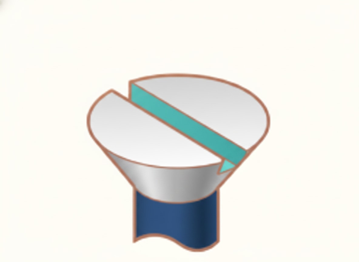
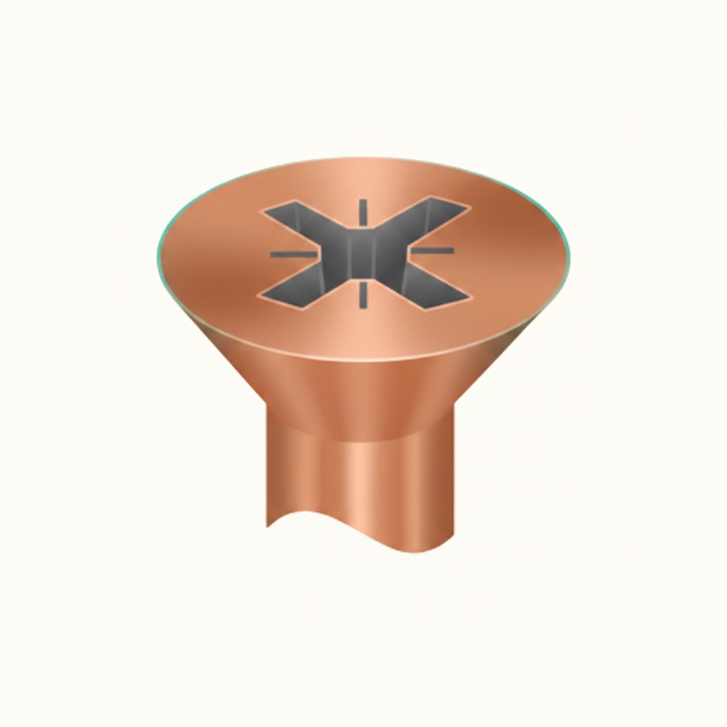
Countersunk screw. Screw head that sits flush with the surface when driven fully in. General-purpose; suits most applications.
Round-head screw (dome-head). Screw head remains visible above the surface. Used where the screw is visible and appearance matters — decorative applications.
Pan-head / self-tapping screw. The self-tapping version has threads running the full length (including up to the head). Used for fixing two or more thin sheets (metal sheet, flashing) — designed for use fixing sheet metal. Not for timber or masonry primarily.
Mirror screw (chrome-plated with a decorative cap). Screw with a chrome cap that screws on top to hide the head. Used for fixing bath panels and decorative mouldings. The cap gives a neat finish.
Fixing WC pans to the floor uses brass screws — they're rust-resistant in a bathroom environment and the brass appearance complements traditional WC pan designs. Not self-tapping (A — those are for sheet metal), not steel (B — rusts), not roundhead (D — not the specific answer for WC pans).
Self-tapping screws are designed for fixing to sheet metal. Not MDF (A), not plywood (B), not concrete (D — concrete needs masonry fixings).
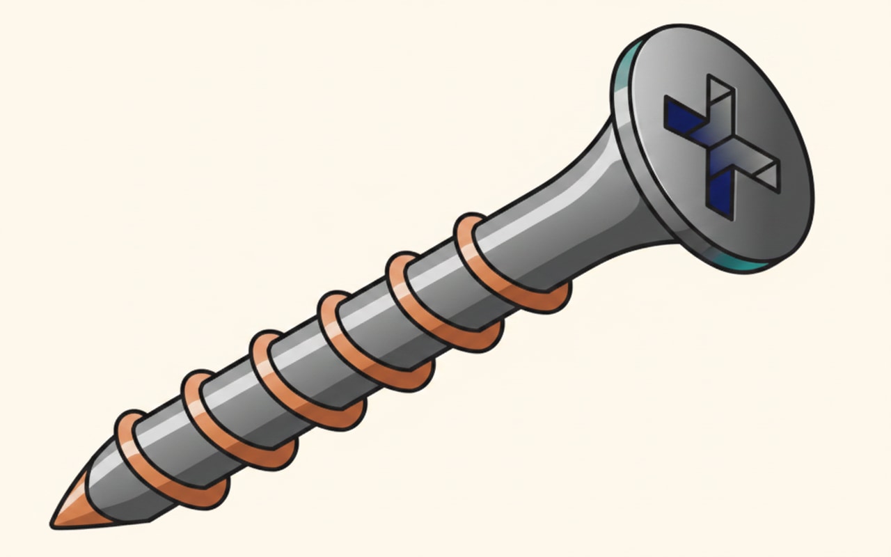
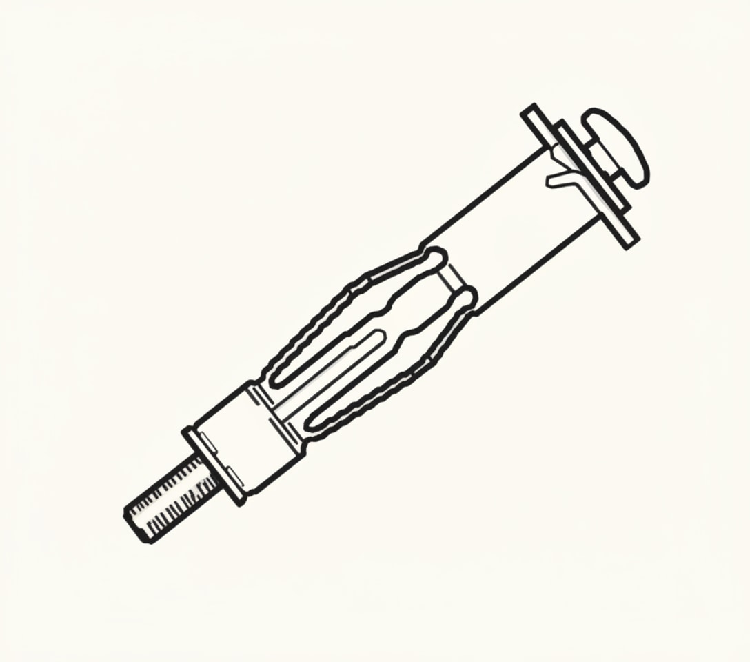
Screwdriver types
Slotted. Flat blade fitting a slot. Oldest screw type; still common.
Phillips. Cross-shaped drive; self-centring.
Pozidrive. Similar to Phillips but with extra spurs between the cross arms. Better torque transfer than Phillips; more modern.
Identifying screws by drive type (slotted/Phillips/Pozidrive) is a common exam question.
Fixings — when screws alone won't work
Different wall types need different fixing methods:
Drive-in fixings (plasterboard plugs). Screw body drives into soft plasterboard. The main screw then goes into the body. Should only be used to fix light things.
Hollow wall anchor (cavity fixing). "Opens up" behind the wall as the screw is tightened, gripping the back surface of the plasterboard. Used for light items in plasterboard walls or cavity constructions.
Rawlbolt. Heavy-duty masonry fixing — expands into the wall as it's tightened, creating a strong mechanical grip. For load-bearing fixings.
Coach bolt / coach screw. Large bolt with a square neck (to prevent rotation). For heavy-duty wooden fixings.
Toggle bolt. Fixing with wings that flip open behind a cavity wall. For hollow walls where heavier fixings are needed than drive-in fixings.
Plastic wall plug (standard "rawl plug"). Pushed into a drilled hole; screw driven in expands the plug, gripping the wall. General-purpose masonry fixing. Fixings in plasterboard surfaces use plastic plugs — not rubber nut fixings, not coach bolts, not wall bolts.
Nails
Oval wire nail. Cross-section is oval rather than round, making the nail less likely to split the wood along the grain. Used in wood where appearance is important.
Cut clasp nail. Rectangular section, tapered. Also used in wood; stronger grip than wire nails.
Masonry nail. Hardened steel nail for driving into masonry, concrete, or mortar joints.
Roofing nail. Short, large-head galvanised nail for securing roof felt and similar materials.
Nail gun / cartridge gun. Used to place drive-in fixings — fires fixings into concrete or masonry much faster than hand-driving. Not a fixing gun (D — not a standard name); not a wall plug gun (C — not a real tool); not a standard drill (irrelevant). A nail gun is the correct answer for drive-in fixings placement.
Lead fixings
Lead sheet (flashing, valley lining, chimney work) uses specific fixings:
Stainless steel screws are a recommended fixing for sheet lead. Stainless resists the galvanic corrosion that would occur between lead and many other metals. Not wrought iron bolts (A), not polyethylene nails (C — they're too weak), not gunmetal rivets (D — specialist and uncommon).
Common exam traps
Trap 1: Minimum joist depth 100mm before any notching or drilling.
Trap 2: Notching: 0.07×span / span÷4 / depth÷8.
Trap 3: Drilling: span÷4 / 0.4×span / depth÷4 / 3×diameter spacing.
Trap 4: Chasing walls: horizontal ⅙ / vertical ⅓.
Trap 5: Copper 15mm H = 1.2m; V = 1.8m.
Trap 6: Copper 22mm H = 1.8m; V = 2.4m.
Trap 7: Plastic 15mm H = 0.3m (much less than copper!).
Trap 8: Plastic 28mm H = 0.8m; V = 1.0m.
Trap 9: LCS ½" H = 1.8m; V = 2.4m.
Trap 10: 110mm uPVC soil pipe horizontal = 1.2m clipping distance.
Trap 11: Heating pipes rigidly fixed = expansion/contraction noise.
Trap 12: Stand-off clips used for insulated pipework.
Trap 13: Bath panels = mirror screws. WC pans = brass screws.
Trap 14: Plasterboard fixings = plastic plugs / hollow wall anchors for light items.
Trap 15: Sheet lead = stainless steel screws.
Trap 16: Self-tapping screws = sheet metal.
Quick revision summary
Before the mock test, eight things you need to be able to produce from memory:
- Part A of Building Regs = structural strength (notching, drilling, chasing)
- Minimum joist depth: 100mm before notching/drilling
- Notching: closest 0.07×span; farthest span÷4; max depth depth÷8
- Drilling: closest span÷4; farthest 0.4×span; max diameter depth÷4; spacing 3×diameter
- Chasing walls: horizontal ⅙ / vertical ⅓ wall thickness
- Copper clip spacing: 15mm = 1.2H/1.8V; 22/28mm = 1.8H/2.4V
- Plastic clip spacing: much shorter (15mm = 0.3H/0.5V)
- LCS clip spacing: longest (½" = 1.8H/2.4V; ¾"/1" = 2.4H/3.0V)
📝 10-Question Mock Test
Click an option to see whether you got it right. Explanations appear instantly — no submitting at the end.
Structural strength is covered by Part A of the Building Regulations. Part B (B) is fire safety; Part F (C) is ventilation; Part L (D) is conservation of fuel and power.
The minimum joist depth before any notching or drilling. Joists shallower than 100mm can't tolerate the structural weakening. Options A, B and D are all below the safe threshold.
Applying the rule: depth ÷ 8 = 250 ÷ 8 = 31.25mm, rounded down to 31mm. Options A (23 — wrong calculation), B (27 — wrong calculation) and D (35 — over the limit) don't match the formula.
Applying the rule: depth ÷ 4 = 220 ÷ 4 = 55mm. Options A, B and C are all below the maximum allowed.
The minimum hole-to-hole spacing rule. Keeps the remaining joist material strong enough between holes.
Horizontal chases have more structural impact than vertical, so the depth limit is more restrictive. Vertical chases can go up to ⅓ of wall thickness. Options A and B are too deep; D is more restrictive than required.
The standard workbook figure for horizontal 15mm copper. 1.8m (D) is the vertical figure for 15mm copper, or the horizontal figure for 22/28mm. 1.4m (B) and 1.6m (C) aren't the standard table values.
Plastic water pipe needs much tighter clipping than copper — 15mm plastic horizontal = 0.3m. Option B (600mm) is the vertical distance for 22mm plastic. C and D are over the limit.
22mm vertical copper = 2.4m. 1.8m (C) is the horizontal figure for 22mm copper, or the vertical for 15mm copper. A (1.2m) is 15mm horizontal copper. B (1.5m) isn't a standard value.
Hot water causes copper to expand and cool water to contract — rigid fixing traps the movement, releasing it noisily. Option A (rupture) doesn't typically happen. Option B (efficiency) isn't affected by clipping tightness. Option C (corrosion) is about chemistry, not mechanical fixing.
How PlumbMate puts this into practice
Installation content is heavy on specific figures — clip spacing, joist calculations, fixing-to-application matching. The fact-dense nature of this topic is where spaced repetition shines.
- Flashcards, not essays. One prompt, one answer — the format that research has consistently shown works best for active recall.
- Wrong answers are logged. Every question you get wrong goes into a dedicated collection that resurfaces more frequently in future sessions.
- The 3× rule. You need to get a question right three times before it clears — one lucky guess isn't enough.
- Explanations on every question. Like the ones above, but on every single question in the app.