A boiler on its own is just a water heater. What turns it into a controllable, efficient heating system is the collection of pumps, motorised valves, thermostats and programmers wired around it. Level 2 tests every one of these components individually, plus boiler interlock (how they work together), automatic bypass valves, air vents and air separators. This post covers all of it, with a ten-question mock test at the end.
This is the controls deep-dive within the Level 2 heating cluster. For the system types these controls fit into, see the heating system types post. For radiator valves (TRVs, lockshields, wheel heads) and radiator types specifically, see the heat emitters and radiator valves post — those sit naturally alongside controls but are big enough to have their own home. For where all this sits in a complete system, see the Level 2 plumbing heating revision guide.
The circulating pump
Part L of the Building Regulations requires almost all new heating installations to be fully pumped — meaning a pump drives water round the heating circuit and to the hot water cylinder rather than relying on gravity. Gravity circulation is slow and inefficient; pumped circulation is fast and manageable.
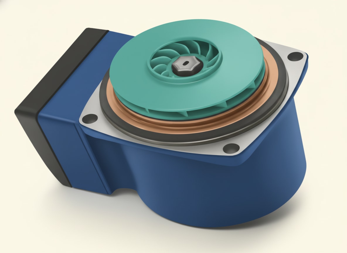
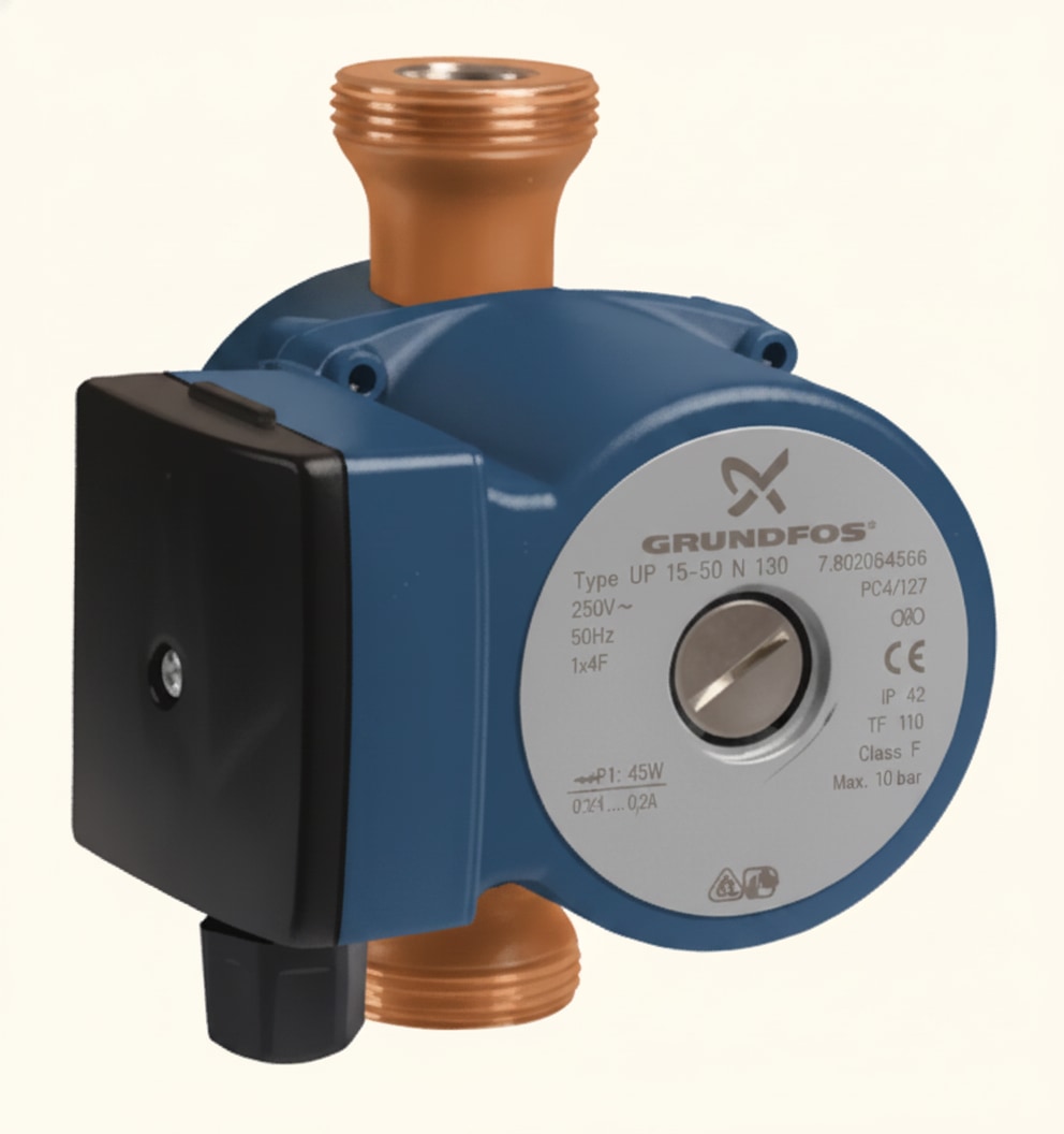
The pump on a domestic system is a centrifugal pump with an impellor inside it. The impellor spins and drives water from the inlet (creating negative pressure behind it) to the outlet (creating positive pressure in front of it).
Three things to know about pump installation:
- The pump must have service valves on both sides, so it can be removed for maintenance or replaced without draining the whole system
- The seal between the pump and its service valve is made with a fibre or rubber washer — not PTFE tape
- The pump is powered from a fused switched spur, typically with a 3-amp fuse
Motorised valves
Motorised zone valves divide the heating circuit into sections. In a typical domestic system there are two zones — the heating circuit and the hot water cylinder — each with its own motorised valve. Larger properties may have multiple heating zones.
Two main types appear in Level 2:
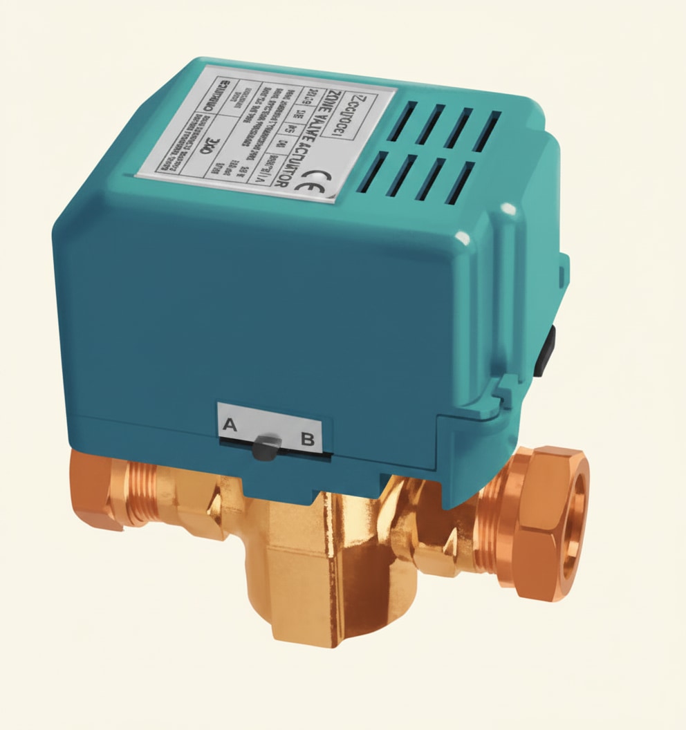
2-port valve
The simplest type. Used in S Plan systems, with one 2-port valve for heating and a second for hot water. Always fit a 2-port valve with the arrow on the body pointing in the direction of flow.
3-port mid-position valve
A single valve that serves both circuits. Used in Y Plan systems. Three ports:
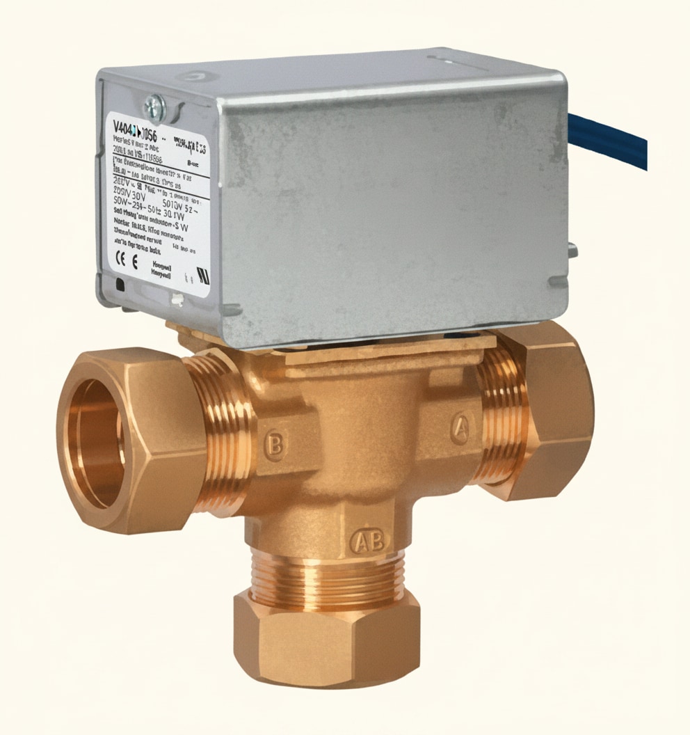
- Port AB — common inlet from the boiler flow
- Port A — outlet to heating
- Port B — outlet to hot water
The "mid-position" feature means it can supply heating, hot water, or both simultaneously. This is the modern 3-port valve and the one you'll meet most often on sites still running a Y Plan.
3-port diverter valve
The older 3-port variant. Unlike the mid-position, it can only serve one circuit at a time — typically with hot water priority (the heating circuit closes while hot water is being heated). Found in W Plan systems, not installed new today, but you'll still come across them.
All motorised valves open and close using a synchronous motor inside the valve head. If the valve stops working, the motor head can often be replaced on its own without draining the system.
Programmers
The programmer controls when the heating and hot water run — not what temperature they run at. A full programmer lets you set independent schedules for the two circuits.
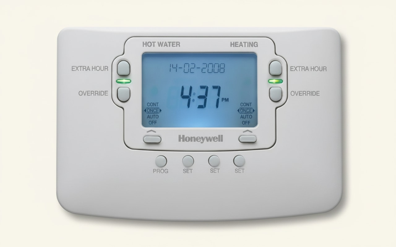
Programmable room thermostats combine time control with room temperature control, allowing different set temperatures at different times of day. This is recommended as best practice in the CHeSS document (Central Heating System Specifications, published by the Energy Saving Trust).
The exam point to keep straight: the programmer controls time, not temperature. Temperature control is the thermostat's job.
Thermostats
Four types of thermostat appear in Level 2.
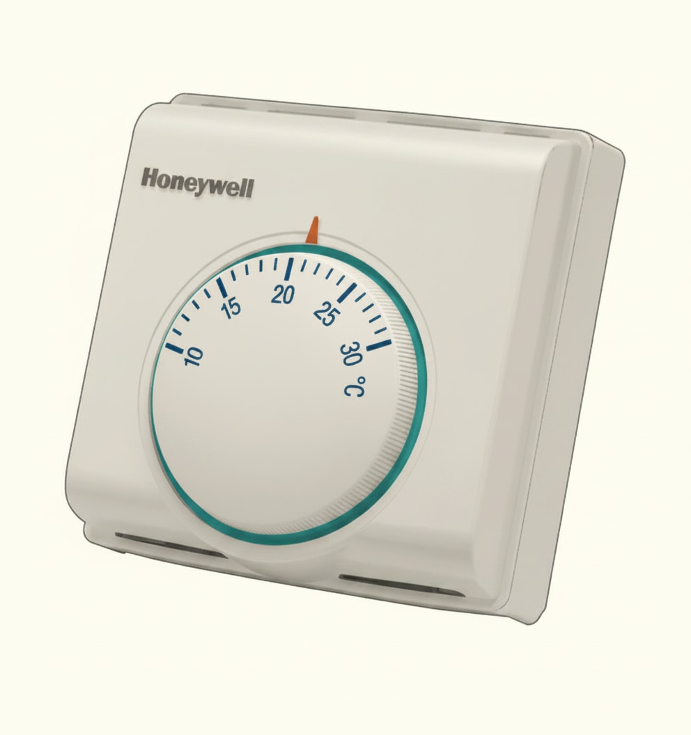
Room thermostat
Senses the air temperature in the room it's installed in and switches the heating on or off accordingly. Should be mounted at approximately 1.5 metres from floor level — high enough to avoid the cold air at the floor and the warm air at the ceiling. Building Regulations require it to be fitted in the main living area of a new property.
Cylinder thermostat
Strapped to the outside of the hot water cylinder to sense the temperature of the stored water. Position approximately one-third of the way up from the bottom of the cylinder. Typically set to 60°C (sometimes 65°C). A built-in overheat stat provides a safety backup if the main thermostat fails.
Frost thermostat
Senses low ambient temperature and switches the heating on to protect pipework from freezing. Set to around 5°C. Fitted where pipework runs through unheated spaces — garages, loft plantrooms, outbuildings.
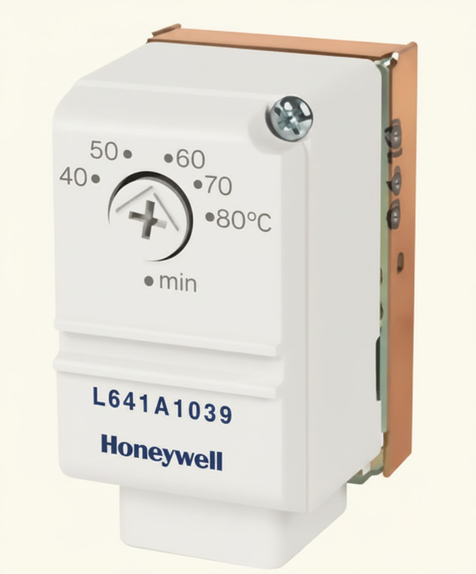
Pipe thermostat
Used alongside a frost thermostat. Senses pipe temperature and switches the system off once the pipework has warmed enough. Set to around 25°C, sited on the boiler return. Many programmable thermostats have this function built in, so a separate pipe stat isn't always needed.
Boiler interlock
Every component covered so far does one job. Boiler interlock is how they work together so that the boiler and pump only run when something in the property actually wants heat.
The principle comes from Part L of the Building Regulations: an energy-efficient system must not let the boiler fire while every thermostat is satisfied and every motorised valve is closed. If the programmer is switched on but nothing is calling for heat, the boiler and the pump should both be off.
Four components combine to achieve this:
- Programmer — has the user scheduled heating or hot water to run right now?
- Room thermostat — does the room still want heat? If satisfied, no demand on the heating circuit.
- Cylinder thermostat — does the cylinder still want heat? If satisfied, no demand on the hot water circuit.
- Motorised valve end switches — as each zone valve opens, its end switch closes and signals the boiler to fire; as the valve closes again, that signal drops.
Only when at least one end switch is closed does the boiler receive a genuine call for heat.
What goes wrong without interlock. A non-interlocked boiler short-cycles — firing until its own boiler thermostat is satisfied, cutting out, cooling, firing again — even when no radiator or cylinder needs the heat. That wastes fuel, wears the boiler and the pump, and is exactly why Part L made interlock a legal requirement for new and replacement installations.
Combi boiler note. Combi boilers provide hot water instantaneously, so DHW interlock is handled inside the boiler electronics rather than by an external cylinder thermostat. The heating side still interlocks in the way described above.
Automatic bypass valve
If every motorised valve on a fully pumped system closes at the same time — heating circuit satisfied, hot water satisfied, every TRV shut — the pump suddenly has nowhere to send the water. That creates back-pressure on the pump (damaging it) and leaves hot water trapped in the boiler heat exchanger (damaging that too).
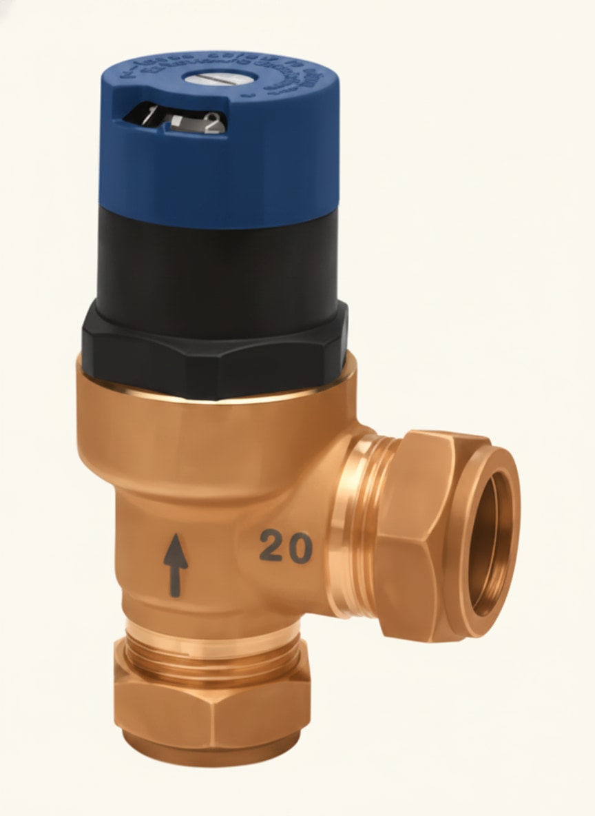
The automatic bypass valve fixes this. It's a spring-loaded valve fitted between flow and return. When system pressure rises above a preset level — which is what happens when the main circuits close — the bypass opens and lets a small flow circulate back to the boiler through it.
The exam fact: the automatic bypass valve is activated by system pressure, not by temperature. It's commonly confused with pressure-relief valves, which are a safety component on sealed systems doing a different job.
Many modern boilers have a bypass built in, so check the manufacturer's instructions before fitting an external one.
Air separator and automatic air vent
Air in a heating system is a nuisance: it pools in radiators (cold spots at the top), corrodes steel components, and makes pumps noisy. Two components manage it.
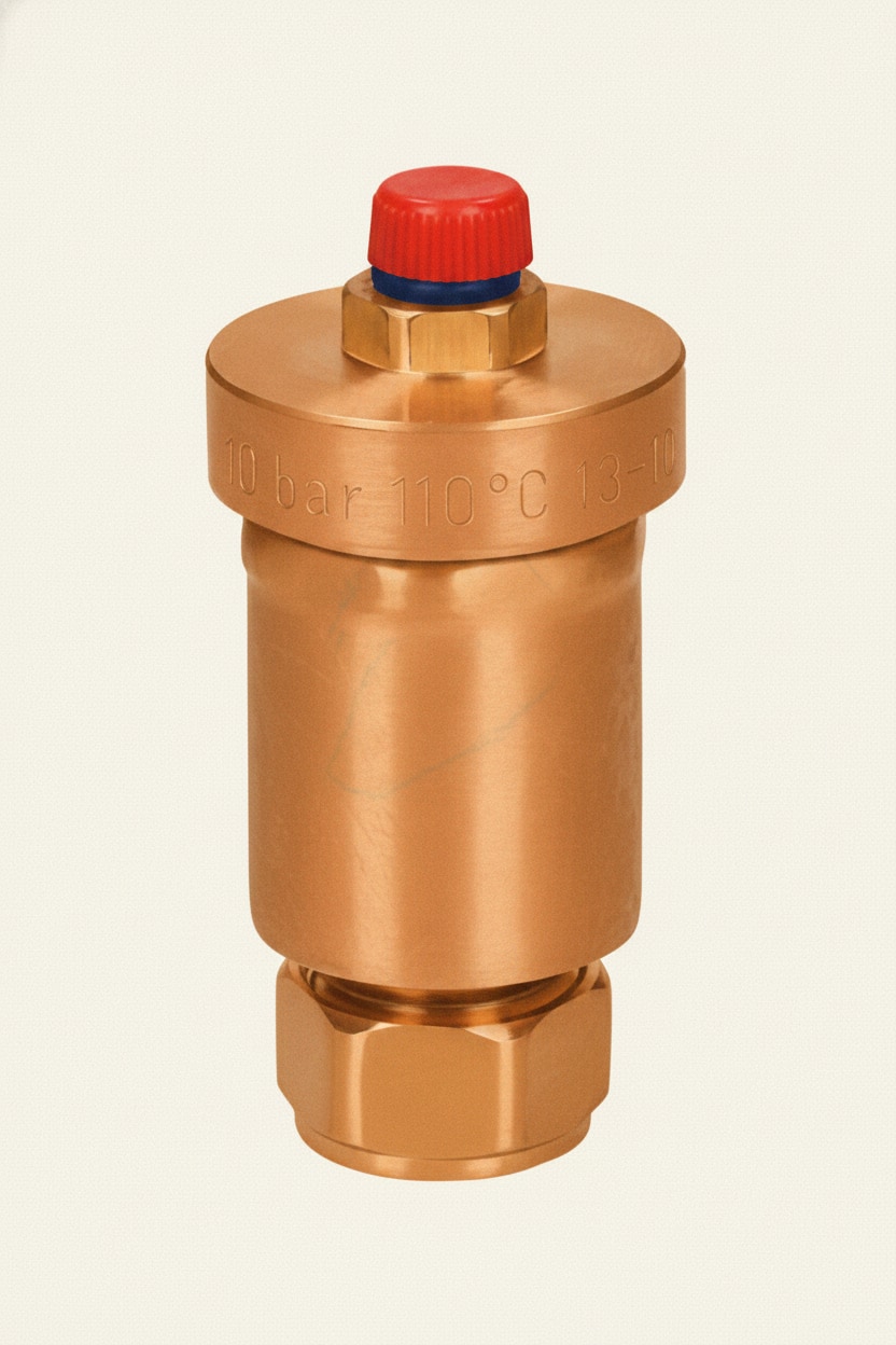
Automatic air vent. A small valve fitted at the highest points of the system, or anywhere a local airlock could form (a pipe that rises and then drops again). A float inside rises as water fills the vent, and any trapped air escapes past it. Once the air has gone, the float seals the vent.
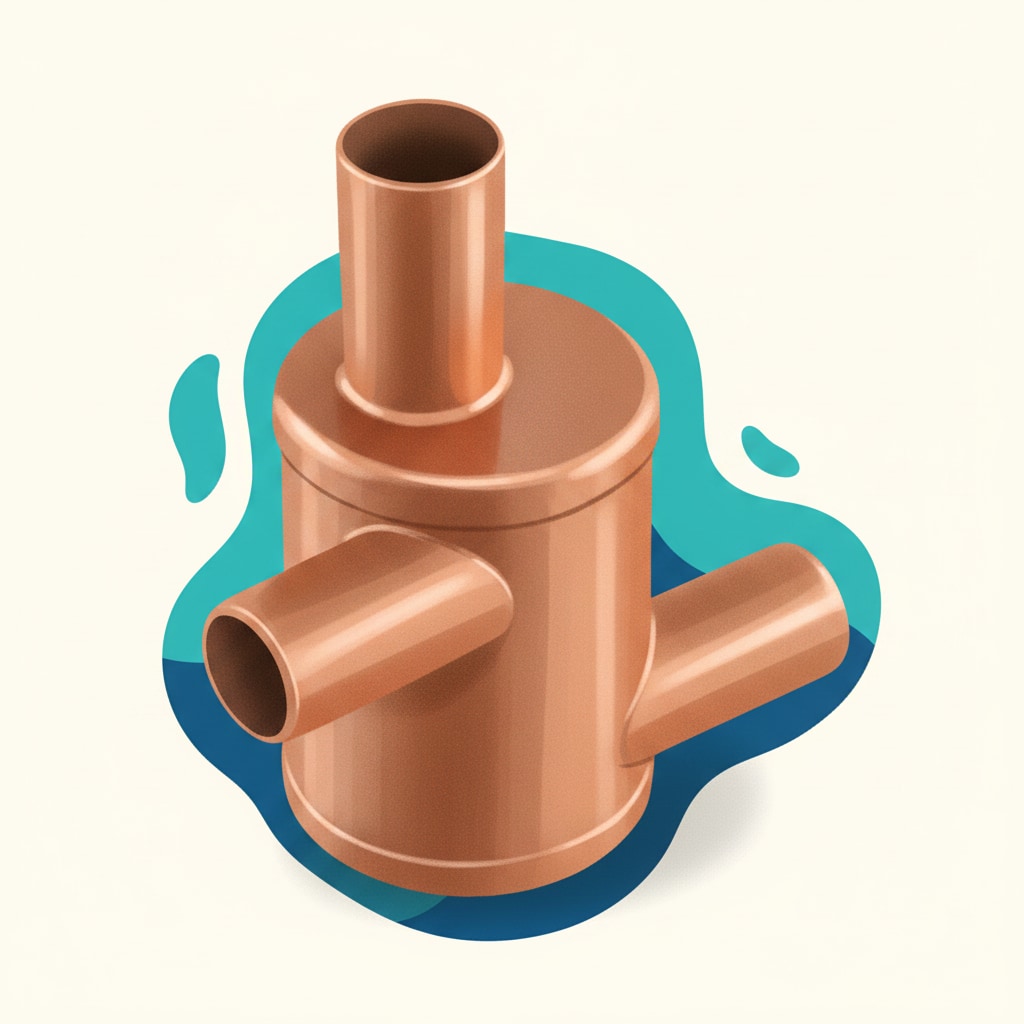
Air separator. A cylindrical vessel fitted into the primary circuit near the boiler. It allows close coupling of the flow pipe from the boiler, the return pipe to the boiler, the cold feed from the F&E cistern, and the open vent pipe — four connections meeting at one component. Its cylindrical shape lets air bubbles rise out of the circulating water and up into the open vent.
Common exam traps
Trap 1: Port AB on a mid-position valve. AB is the common port (the boiler flow in). A goes to heating, B goes to hot water. Students guess A is "first" and assume it's the inlet, which it isn't.
Trap 2: Cylinder thermostat position. One-third up from the bottom (two-thirds down from the top). A common mistake is to put it near the top, where it sits in permanently hot water and never senses a drop in cylinder temperature.
Trap 3: Automatic bypass valve trigger. Pressure-activated, not temperature. Gets confused with pressure-relief valves because the names sound similar.
Trap 4: Pump service valves. Both sides, not just one. Both sides need to isolate so the pump can be removed.
Trap 5: Frost stat on its own isn't enough. If the frost stat is in an unheated space and there's no pipe stat, the system will keep firing indefinitely once it switches on. The pipe stat on the boiler return senses when the pipework has warmed and switches the system off again.
Quick revision summary
Ten things to produce from memory before the exam:
- Pump: centrifugal, impellor, service valves each side, fibre/rubber washer on the face seal
- 2-port valve: arrow on body must point in direction of flow
- Mid-position (3-port) valve ports: AB = boiler flow, A = heating, B = hot water
- Motorised valve motor: synchronous
- Programmer: controls when (time), not what temperature
- Room thermostat: 1.5 metres from floor, main living area
- Cylinder thermostat: one-third up from bottom, ~60°C
- Frost stat / pipe stat: 5°C / 25°C on boiler return
- Boiler interlock: programmer + thermostats + motorised valve end switches; Part L requirement; prevents short-cycling
- Automatic bypass valve: pressure-activated, not temperature
📝 10-Question Mock Test
Click an option to see whether you got it right. Explanations appear instantly — no submitting at the end.
Inside a centrifugal pump, the impellor is the rotating component that drives the water — creating suction at the inlet and positive pressure at the outlet. Booster, spreader, and injector aren't the moving part of a pump.
Pump service valves (isolating valves) fitted each side of the pump allow it to be removed, serviced or replaced without draining the system. The face seal against the pump body is made with a fibre or rubber washer — not PTFE.
On a 3-port mid-position valve, AB is the common port that takes the flow from the boiler. Port A goes to the heating circuit and port B goes to the hot water circuit. High-frequency exam question and an easy mark once you've committed the mapping to memory.
The programmer controls when the system runs. Temperature is controlled by the thermostats (room stat, cylinder stat). Water pressure is a separate concern and emergency shut-off is handled differently.
The room thermostat should be mounted at around 1.5 metres from the floor — high enough to read the room's general air temperature, away from the cold air at floor level and the warm air at the ceiling. Building Regulations also require a new property's room thermostat to be fitted in the main living area.
The cooler water in a cylinder sits at the bottom, so that's where the thermostat needs to sense temperature changes. Place it too high and it sits in permanently hot water and never senses a drop.
A frost thermostat switches the heating on when ambient temperature drops to around 5°C, protecting pipework in unheated spaces from freezing. Used alongside a pipe stat on the boiler return (25°C) to switch the system off once the pipework has warmed.
Boiler interlock is the Part L requirement that the boiler and pump must not run when every thermostat is satisfied and every motorised valve is closed. Options A and D describe unrelated system behaviour; C confuses interlock with a hierarchy between thermostats, which isn't how it works.
The automatic bypass valve opens when circuit pressure rises above a preset level — which happens when the main circuits close. It's pressure-activated, not temperature-activated (an easy trap to fall into because pressure-relief valves do a different job with a similar name).
Air rises to the top of the system, so that's where the automatic air vent belongs. It should also be fitted anywhere a local airlock could form (where a pipe rises and then drops). The float inside rises with the water and allows any trapped air to escape.
Revise this topic the PlumbMate way
PlumbMate turns these facts into something you'll actually remember in the exam:
- Video lessons on every control component, filmed by a plumbing lecturer
- Topic-specific quiz banks on pumps, valves, thermostats, programmers and boiler interlock — so you can target the exact areas you keep dropping marks on
- Spaced-retrieval scheduling that brings weaker topics back on the days you're most likely to forget them
- Mock exams that mix controls questions in with the rest of the heating unit, so you practise switching between topics the way the real exam demands
Start your 14-day free trial at plumbmatemastery.co.uk.