Module 2 gave the two formulae. This one puts them to work on a real house, room by room, and then asks the question that decides the whole design: which room is hardest?
This article covers Module 3 of the PlumbMate low temperature heating course: design temperatures inside and out, the room-by-room method, what the totals are and are not for, and why sizing the heat generator from the sum of the rooms is wrong. There is a 10-question mock test at the end.
Design temperatures: the two ends
Every ΔT in the calculation is the gap between an inside design temperature and an outside one, so both have to be settled before anything is worked out.
Outside
The external design temperature is a regional figure, taken from CIBSE or the Domestic Heating Design Guide. For most of England it is around −3 °C; parts of Scotland use −4 or lower; some southern coastal areas are milder.
It is deliberately not the coldest temperature ever recorded. It is a figure exceeded only for a small number of hours a year. Designing for the record low would oversize everything for a condition that occurs once a decade — and on a low temperature system, oversizing the heat generator is not free.
Inside
Internal design temperatures come from the same guides and vary by room use:
| Room | Design temp | Typical air changes/h |
|---|---|---|
| Living room | 21 °C | 1.5 |
| Dining room | 21 °C | 1.5 |
| Kitchen | 18 °C | 2.0 |
| Bedroom | 18 °C | 1.0 |
| Bathroom | 22 °C | 2.0 |
| Hall / landing | 18 °C | 2.0 |
| Cloakroom / WC | 18 °C | 2.0 |
The bathroom is the highest at 22 °C, and it also carries a high air change rate. Remember that pair — it comes back in Module 4 as the reason a towel rail cannot heat a bathroom on a low temperature system.
Note too that temperature and air changes are chosen together. A kitchen is designed cooler than a living room but ventilated harder, because of what happens in it. Which of those two rooms has the larger heat loss is not obvious in advance. On our worked house they come out 162 W apart.
The method, room by room
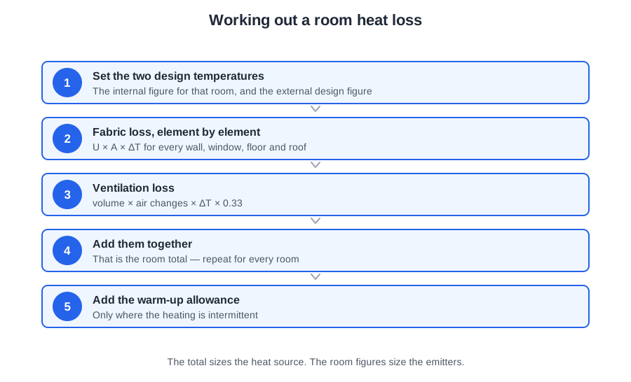
For each room:
1. List every element of the envelope — each wall by orientation, ceiling, floor, each window, each door, each partition.
2. Measure the area of each. Walls gross, then deduct the openings.
3. Assign a U-value to each, with its source recorded.
4. Assign the ΔT that applies to that element — outdoor, half-outdoor to an unheated space, the difference between two rooms for a partition, floor or ceiling, or next door taken at 10 °C for a party wall. A surface to a room at the same temperature goes on at 0 K: it adds nothing, but it stays on the sheet. Where two rooms differ, work the surface once and put the same U × A × ΔT on both sheets: a loss (+) in the warmer room, a gain (−) in the cooler one. Only credit a gain from a room the same system holds at its design temperature.
5. Q = U × A × ΔT for each, and total them, losses less gains.
6. Add the ventilation loss: 0.33 × N × V × ΔT.
7. Net fabric plus ventilation is the room's design heat loss in watts, and the emitter is sized on that net load.
Worked: the living room
A 1970s three-bed semi, external design temperature −3 °C, living room at 21 °C so ΔT = 24 K to outside. The room is 4.2 × 3.6 m, 2.4 m high — 15.12 m² floor, 36.29 m³ volume. It has one external wall at the front with a 1.8 × 1.2 m window. One side is the party wall to next door; the other is a stud partition to the 18 °C hall, with the door in it. Behind it is the 18 °C kitchen, above it bedroom 1 and the landing at 18 °C, and below it the ground. Six faces, and every one goes on the sheet.
| Element, and what is on the other side | A (m²) | U | ΔT | Q (W) |
|---|---|---|---|---|
| Front wall, net of the window · outside | 7.92 | 0.55 | 24 | 104.5 |
| Window · outside | 2.16 | 1.6 | 24 | 82.9 |
| Partition to the hall, net of the door · 18 °C | 7.14 | 2.0 | 3 | 42.8 |
| Door to the hall · 18 °C | 1.50 | 2.2 | 3 | 9.9 |
| Back wall · kitchen, 18 °C | 10.08 | 2.0 | 3 | 60.5 |
| Party wall, unfilled cavity · next door, taken at 10 °C | 8.64 | 1.4 | 11 | 133.1 |
| Floor · ground | 15.12 | 0.70 | 24 | 254.0 |
| Ceiling, heat flowing up · bedroom 1 and landing, 18 °C | 15.12 | 1.7 | 3 | 77.1 |
| Fabric | 765 | |||
| Ventilation 0.33 × 1.5 × 36.29 × 24 | 431 | |||
| Room total | 1,196 W |
The internal U-values are the standard design values from CIBSE’s Domestic Heating Design Guide: 2.0 for a stud partition, 2.2 for a hollow internal door, and 1.7 for the intermediate floor with the heat flowing up through it. The party wall is an unfilled cavity: two leaves, an air gap and plaster work out at about 1.4. The MCS heat load calculator uses 0.50 for it, but that is the RdSAP shortcut for air escaping up the cavity, not heat conducted through to next door, so do not use it here.
Two things to notice. None of the surfaces inside the house is zero. The hall wall and door, the back wall and the ceiling are only 3 K across, but they add 190 W, and the hall, kitchen, bedroom 1 and landing write the same watts down as gains. The party wall adds another 133.1 W, the second largest line, because you cannot count on next door being heated, so it is taken at 10 °C. Leave those off and you lose more than a quarter of the room. And ventilation is 431 of 1,196 W, more than a third, in a room at only 1.5 air changes.
The whole dwelling
| Room | Design temp | Net heat loss |
|---|---|---|
| Living room | 21 °C | 1,196 W |
| Kitchen | 18 °C | 1,034 W |
| Hall | 18 °C | 340 W |
| Cloakroom | 18 °C | 144 W |
| Bedroom 1 | 18 °C | 418 W |
| Bedroom 2 | 18 °C | 362 W |
| Bedroom 3 | 18 °C | 210 W |
| Bathroom | 22 °C | 491 W |
| Landing | 18 °C | 142 W |
| Total | 4,337 W |
The living room and the kitchen are the two big loads, and they get there differently. The living room is the biggest, 162 W clear of the kitchen: it is the warmest main room, so every surface to a cooler room is a loss, and its party wall works at 11 K. The kitchen is designed 3 K cooler, but it has more external wall, more glazing and, decisively, a third more air changes, less the 87 W it gains from the living room and the bathroom above. The bathroom is the other surprise: at 22 °C it is warmer than every room around it, so its walls, door and floor to the rest of the house all carry a loss, and the rooms around it take the same watts as gains.
Add up the nine net room loads, or add up only the surfaces to outside and next door: both give 4,337 W, because every gain cancels the matching loss. Every warmer room here is held at its design temperature by the same system, so every gain counts. If a warmer room might be switched off, treat it as unheated and take no gain from it.
What the total is for — and what it is not
4,337 W is the space heating design load at the design outside temperature. It sizes the heat generator's space heating duty.
It is not the sum of the emitter outputs you will install, and this catches people out. Room emitters are sized to their own rooms and then rounded up to the next catalogue size, so the installed output always exceeds the calculated loss. On our house it comes to nearly 12 kW of ΔT50 radiator to deliver 4.3 kW at 45/40. Sizing the heat pump from the radiator schedule would give a 12 kW unit on a house that needs 4.3.
Nor does it include the hot water load, which is worked separately in Module 5 and which does not coincide with the space heating peak.
Watts per square metre — a sanity check, not a method
Divide 4,337 W by 76.28 m² and you get about 57 W/m². That is a reasonable figure for a partially improved 1970s semi. A well insulated modern dwelling comes out nearer 25 to 35; an unimproved solid-wall Victorian house can exceed 100.
Used as a check on a completed calculation, that is a useful instinct. Used instead of a calculation, it is a guess — and it cannot tell you a single room's emitter size, which is the thing you actually need.
Intermittent heating and the warm-up allowance
The calculation above is a steady-state one: the building already at temperature, holding it. A system that is off overnight has to do more than hold — it has to bring the structure back up.
Traditional practice added a warm-up allowance, often 10 to 15%, sometimes more for intermittent heating of a heavy building. It matters much less on a low temperature system, because these are generally designed to run continuously with weather compensation rather than in on/off bursts. A heat pump reheating a cold house from setback fights its own efficiency curve.
The honest position: if the system is designed to run continuously, no warm-up allowance is needed and adding one oversizes the plant. If it will genuinely be run intermittently, allow for it — and say so, because it changes the sizing.
What is never right is adding a blanket percentage “to be safe”. On an 80 °C system that produced a slightly large radiator. On a low temperature system it produces a heat pump that cycles.
Recording it
The output of this module is a document, not a number. Each room, each element, each area, each U-value with its source, each ΔT, each air change rate with its source, and the totals. The external design temperature and its source. Any assumptions, flagged as assumptions.
That record is what lets someone check the design, what lets you defend it if the house does not perform, and what MCS asks to see on a certified installation. A spreadsheet with the answers and none of the workings is not it.
📝 10-Question Mock Test
Click an option to see whether you got it right. Explanations appear instantly — no submitting at the end.
And it is deliberately not the coldest ever recorded — it is exceeded only for a few hours a year. Designing for a record low oversizes everything for a once-a-decade condition.
And it also has a high air change rate. That pair is why a towel rail cannot heat a bathroom on a low temperature system.
Though the kitchen's higher air change rate often brings its total loss close to the living room's, or past it. On the worked house the kitchen comes within 162 W of the living room.
The bedroom is heated, but to 18 °C, not 21. 15.12 m² × 1.7 × 3 K is 77 W, a loss on the warmer room's sheet. Bedroom 1 and the landing write the same watts down as a gain. The party wall is not zero either: next door is taken at 10 °C.
More than a third of the loss, in the room with one of the lower rates in the house. In a kitchen or bathroom at 2.0 it is a larger share still.
Not the emitter total — that comes to nearly 12 kW of ΔT50 radiator once each room is sized. Sizing the heat pump from the radiator schedule would give a 12 kW unit on a house needing 4.3.
You cannot buy a 1,196 W radiator. Every room rounds upward, so the schedule total is always the larger figure — which is exactly why it must not be used to size the heat generator.
About 57 W/m² here, reasonable for a partly improved 1970s semi. Used instead of a calculation it is a guess, and it cannot give you a single room's emitter size.
A heat pump reheating a cold house from setback fights its own efficiency curve. If the system genuinely will run intermittently, allow for it — and record that you have.
It is what lets someone check the design, what lets you defend it if the house underperforms, and what MCS asks to see. Answers without workings are not a design.
Room by room, with the right ΔT on every element and the ventilation rate taken from a table rather than a hunch. Everything after this is arithmetic performed on these nine numbers.