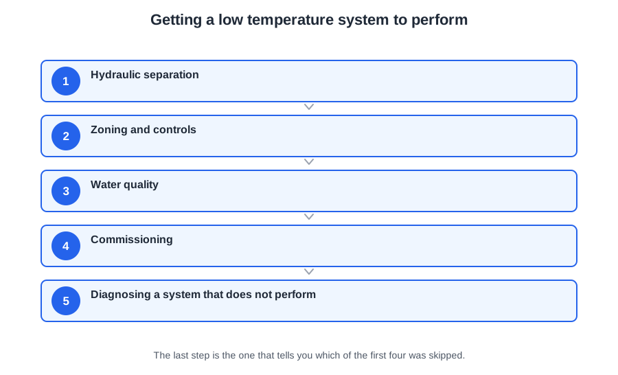
All the components are now sized. This module is about how they go together, how they are controlled, how the system is proved, and what to do when a design that should work does not.
This article covers Module 7 of the PlumbMate low temperature heating course: hydraulic separation and when you actually need it, zoning and weather compensation, water quality, the commissioning sequence, and how to diagnose an underperforming low temperature system. There is a 10-question mock test at the end.
Hydraulic separation
A buffer vessel or a low loss header separates the heat generator's circuit from the emitter circuit, so the two can run at different flow rates without fighting each other.
Both are fitted routinely. Both are frequently unnecessary. And both carry a real cost, which is why “fit one to be safe” is the wrong instinct.
The cost
Mixing. If the vessel allows hot flow to blend with cool return, the emitter circuit gets water cooler than the heat pump is producing. To get 45 °C at the radiators the appliance now has to make 48 or 50 — and every one of those extra kelvin is 2 to 2.5% of the efficiency the whole design was for.
Standing loss. A poorly insulated buffer in an unheated space loses heat continuously, and that loss is made up at the heat pump's COP.
Cost and space, in a house that usually has neither spare.
When you genuinely need one
System volume below the manufacturer's minimum. A real, checkable arithmetic reason. Add up the emitter contents and the pipework and compare it to the manual.
Minimum flow cannot be guaranteed. Where every zone can close — heavily zoned systems with TRVs everywhere — the heat pump can be left with nowhere to circulate.
Genuinely different flow rates or temperatures. Underfloor at 35 °C and radiators at 45 on the same generator, or a defrost cycle needing a heat store.
The manufacturer requires it. Some units simply do, and that ends the discussion.
If none of those apply, do not fit one. And where separation is needed, a volumiser in the return — a plain vessel adding volume in series — adds the water without introducing the mixing, which is often the better answer. A 2-pipe buffer in the return does the same job. It is the 4-pipe buffer that mixes.
Zoning and controls
The minimum is in Approved Document L 2021 (which replaced the Domestic Building Services Compliance Guide in June 2022): separate time and temperature control of space heating and hot water, and in a new dwelling of 150 m² or more, at least two independently controlled heating circuits (paragraph 5.14). Most heat pumps go into existing homes, and there the rule is paragraph 5.20: when a heat generator such as a boiler is replaced, each room should have thermostatic room controls.
On a low temperature system, resist over-zoning. Every zone that can close is a circuit the heat pump can lose, and the minimum flow rate has to survive all of them shutting at once. Keep one room permanently open — typically the hall, or the bathroom — without a TRV, so there is always somewhere for the water to go.
Weather compensation
This is the control strategy the whole subject points at. An outside sensor tells the controller the external temperature, and the flow temperature is raised or lowered along a compensation curve: 45 °C at the design condition, perhaps 32 at 10 °C outside.
The gain is exactly the gain from Module 1. A system that spends most of the heating season at 35 °C rather than a fixed 45 is running 10 K cooler for most of its life — 20 to 25% on the efficiency, across most of the year.
And it explains why a low temperature system should run continuously at a low output rather than in on/off bursts. A traditional system with big margins recovers a house from setback quickly. A low temperature system has no such margin: reheating from cold takes hours it does not have, and it must do it at the top of its flow temperature range, which is its least efficient point.
The householder needs to be told this at handover, in plain terms: leave it alone, do not turn it off overnight, do not turn it up to warm the house faster. A system operated like an 80 °C one will disappoint, and that is not the householder's fault if nobody explained it.
Water quality
BS 7593 requires the system to be cleaned, flushed, dosed with inhibitor, and the inhibitor concentration verified — then checked periodically thereafter.
It matters more here than it used to. Magnetite in a heat pump's plate heat exchanger restricts flow through narrow passages, and the appliance sees it as a flow fault. Sludge in an oversized low temperature radiator settles in the bottom, where the water is moving slowly, and takes output off the emitter that had none to spare. A magnetic filter is standard practice and, on a heat pump, close to essential.
On a retrofit onto existing pipework, a chemical clean and power flush before the new appliance goes on is not optional. Everything the old system accumulated is otherwise about to arrive in a new heat exchanger.
Commissioning
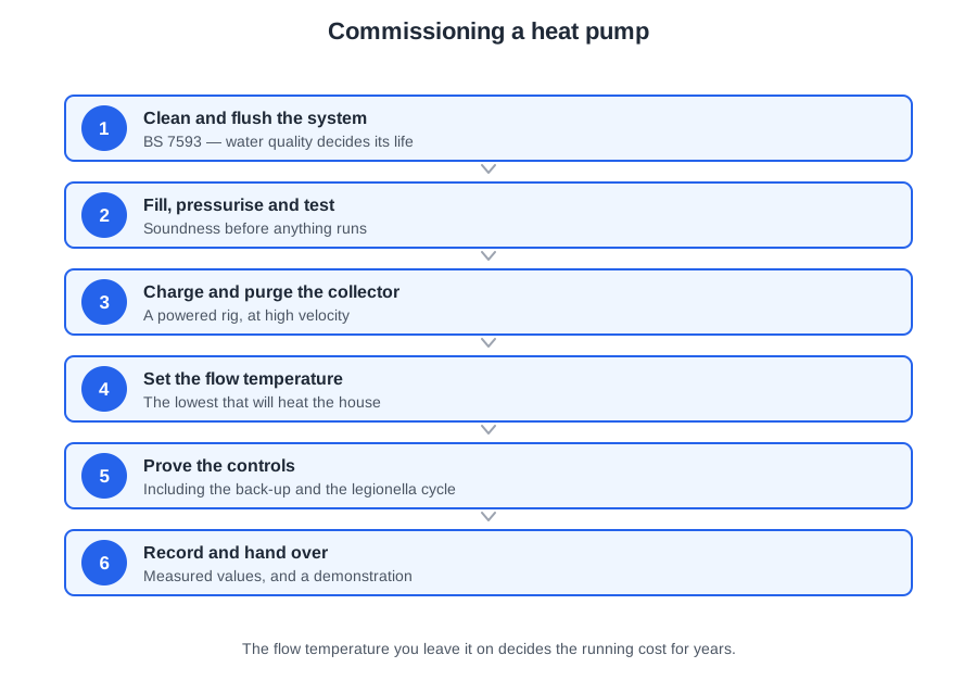
The sequence, in order:
1. Clean and flush to BS 7593, then dose and verify the inhibitor.
2. Fill and vent. Air at every high point, and vent the emitters individually — a partly airlocked radiator on a low temperature system is the difference between a warm room and a cold one.
3. Pressure test and set the expansion vessel charge to the cold fill pressure, with the system drained or the vessel isolated.
4. Set the pump to the calculated duty and the correct control mode — usually proportional pressure on a TRV system.
5. Balance. Set each circuit's lockshield so every emitter achieves its design flow rate. Record the return temperatures.
6. Set the controls — compensation curve, hot water charge time, pasteurisation cycle.
7. Verify performance. Flow and return at the appliance, flow rate, the cylinder reaching 60 °C, TMV outlet temperatures.
8. Record everything and hand over.
Balancing, and why it is not optional now
On an 80 °C system an unbalanced circuit produced a room slightly cooler than the others and a return warmer than it should be. Both were absorbed by the margin.
On a low temperature system there is no margin. An emitter short of its design flow does not reach its mean water temperature, so it does not reach its output, and a room that was calculated to be warm is not. A return that comes back too warm stops the boiler condensing or pushes the heat pump off its curve.
Balancing is measured, not judged by hand on a pipe. And the record of it is what lets you demonstrate the system was set up correctly if the house is later said to be cold.
Diagnosing a system that does not perform
The discipline is to work from the design outward, in order of cost, and to check the cheap things first.
One room cold, others fine. That is a room-level fault: the emitter, its flow, or its TRV. Check the emitter against the schedule, then the balancing, then the valve. Not a plant fault.
Every room cold. Plant, flow temperature or flow rate. Check the actual flow temperature against the design, then the flow rate against the manufacturer's minimum, then the heat generator.
Rooms warm, running cost high. The system works; it is running inefficiently. Check the return temperature, whether the compensation curve is set or the system is running at a fixed high flow temperature, whether a buffer is mixing, and whether the hot water is charging repeatedly.
Appliance cycling. System volume or flow rate below the minimum, or the generator oversized for the load. This is where an oversized heat pump on an over-zoned system reveals itself.
Far end cold, near end fine. Pump head, pipe size, or balancing — and given Module 6, suspect the pipework was never re-checked for the new flow rate.
And one case worth naming, because it is the one people diagnose wrongly. A house that is comfortable, cheap to run, and where the customer says the radiators feel cool is not faulty. It is a correctly designed low temperature system. The radiators are supposed to feel warm rather than hot; that is the whole point. The fix is an explanation, not a component — and it belongs at handover rather than at a callback.
📝 10-Question Mock Test
Click an option to see whether you got it right. Explanations appear instantly — no submitting at the end.
So to get 45 °C at the radiators the appliance must make 48 or 50 — and every extra kelvin is 2 to 2.5% of the efficiency the whole design was for.
Separation is fitted for a checkable arithmetic reason or because the manufacturer requires it. Fitted by default it is a permanent charge on the efficiency.
It adds the water in series without introducing the mixing. A 2-pipe buffer in the return does the same job; it is the 4-pipe arrangement that blends.
150 m² or more, in a new dwelling (paragraph 5.14). That is alongside separate time and temperature control of space heating and hot water in every dwelling.
Typically the hall or the bathroom. Every zone that can close is a circuit the heat pump can lose, and the minimum flow rate has to survive all of them shutting at once.
45 °C at the design condition, perhaps 32 at 10 °C outside. A system spending most of the season 10 K cooler is 20 to 25% more efficient for most of the year.
And the householder has to be told at handover: leave it alone, do not turn it off overnight. A system operated like an 80 °C one will disappoint.
Clean, flush, dose, verify the concentration, then check periodically. Magnetite in a heat pump's plate heat exchanger shows up as a flow fault.
On an 80 °C system an unbalanced circuit gave a slightly cool room and a warm return, both absorbed by the margin. Here a room calculated to be warm simply is not.
Radiators are supposed to feel warm rather than hot; that is the point. The fix is an explanation, and it belongs at handover rather than at a callback.
Seven modules, one thread: the temperature came down, and everything else had to be recalculated to make that work. Design it, prove it, and explain it — because a system nobody understands will be turned up until it costs what the old one did.