A heat pump is the only heating appliance on a domestic job that can deliver more energy than it consumes. That single fact is where most of the confusion starts, and where a lot of bad installations begin — because an engineer who has not understood why it is true will size, pipe and commission the machine as though it were a boiler, and it will disappoint everyone.
This article covers Module 1 of the PlumbMate heat pumps course: what a heat pump actually does, the refrigerant cycle that does it, the components that keep that cycle alive, the three efficiency figures you will be quoted and which of them a customer actually pays, and the one idea — temperature lift — that decides almost everything. There is a 10-question mock test at the end.
Moving heat, not making it
A boiler makes heat. It burns a fuel and the energy released warms the water. Burn a kilowatt of gas and you get slightly less than a kilowatt of heat out — some goes up the flue, some through the casing. However good the boiler, you can never get out more than you put in. That is not an engineering limitation anyone is going to design around; it is thermodynamics.
A heat pump moves heat that already exists, from somewhere you cannot use it to somewhere you can. Moving energy is far cheaper than creating it, so a heat pump typically delivers three or four kilowatts of heat for every kilowatt of electricity it consumes. Nothing is created from nothing — the extra energy was already sitting in the outside air, the ground or a body of water. The electricity is not paying for the heat. It is paying for the upgrade.
There is heat in cold air
This is the idea people find hardest, and it is worth slowing down on because everything else rests on it. Temperature is not the same as heat. Air at 2 °C feels cold to a human being, but it contains an enormous quantity of thermal energy. Everything above absolute zero — −273 °C — contains heat. A heat pump does not need warm air. It needs air that is warmer than the very cold liquid inside its evaporator, and at 2 °C that condition is met easily.
You already own a machine that proves it. A domestic fridge takes heat out of food that is already cold and dumps it into your kitchen through the warm grille at the back. A heat pump is the same machine, turned round so the useful end faces into the house. If you can accept that a fridge cools food that is already at 5 °C, you can accept that a heat pump extracts heat from air at 2 °C.
A heat pump is a heat removal machine pointed the right way. Everything else is detail.
Low-grade in, high-grade out
The heat collected from outside is low-grade: plentiful, but far too cool to warm a room. The machine's job is to upgrade it — absorb it into a refrigerant, then use a compressor to raise the pressure. Raising the pressure raises the temperature, and the heat can then be released into the heating system at a genuinely useful 45 or 50 °C.
Three places to collect from
| Source | Character | The catch |
|---|---|---|
| Air | Free, everywhere, no excavation | Coldest exactly when the building needs most heat |
| Ground | Steady at roughly 8–12 °C all year | Excavation or drilling, and the land to do it on |
| Water | Thermally excellent | Needs the right site, and usually an abstraction licence |
The refrigerant cycle: squeeze, give, drop, take
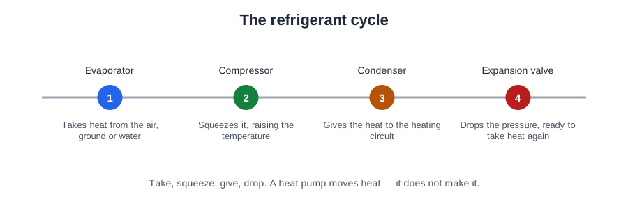
Inside every heat pump is a sealed loop containing a refrigerant, chosen because it boils at a very low temperature. Four components act on it in turn, and the refrigerant changes state twice on every lap.
Why a change of state?
Warming a fluid moves very little energy. Boiling it moves a great deal. The energy absorbed when a liquid becomes a vapour is latent heat of vaporisation, and it is large — which is precisely why steam scalds so much worse than hot water at the same temperature. The circuit boils the refrigerant to absorb heat and condenses it to release heat. That state change is what lets a physically small heat exchanger pull useful energy out of cold air.
The four components, in order
| # | Component | What it does | Refrigerant state |
|---|---|---|---|
| 1 | Compressor | Squeezes low-pressure vapour. Pressure rises, and temperature rises with it. The only component consuming significant electricity. | Vapour in, hot vapour out |
| 2 | Condenser | The hot vapour gives up its heat to the heating water and condenses. This released latent heat is what warms the house. | Vapour → liquid |
| 3 | Expansion valve | A controlled restriction. Dropping the liquid's pressure drops its boiling point. | Liquid, now cold |
| 4 | Evaporator | The cold liquid boils, absorbing heat from the air, ground or water. | Liquid → vapour |
Hold the order as squeeze, give, drop, take. The two heat exchangers always sit opposite one another, separated by the compressor on one side and the expansion valve on the other. If you can name the four in order and say what state the refrigerant is in at each point, you understand the cycle — and that is a standard exam question in exactly that form.
Pressure and boiling point
The whole cycle rests on one relationship: change a fluid's pressure and you change the temperature at which it boils. At high pressure the refrigerant condenses at 50 °C, hot enough to heat water. At low pressure the same fluid boils at −5 °C, cold enough to absorb heat on a frosty morning. The compressor and the expansion valve exist purely to move the refrigerant between those two conditions.
The supporting components
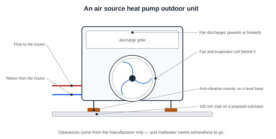
Around the four main components sit several others that keep the circuit clean, protected, and able to shed frost. They are where a lot of diagnostic marks are won.
- Dryer / receiver — a desiccant to absorb moisture and a filter to catch debris. Moisture matters more than people expect: it can freeze at the expansion valve and block it, and it forms acids that attack the compressor windings.
- Sight glass — a window on the liquid line. Clear liquid at steady state is normal. Persistent bubbles suggest an undercharge or non-condensable gases in the circuit.
- Reversing valve — swaps the roles of the two heat exchangers. This is how defrost works, and how a reversible unit provides cooling.
- Pressure switches — high and low pressure switches shut the compressor down before abnormal pressures damage it. Which one tripped tells you which side of the machine to investigate.
A pressure lockout is a symptom, not a fault to reset. Find out why it tripped.
Defrost — and why mild damp weather is the worst
An air source evaporator necessarily runs colder than the outside air; that temperature difference is what drives heat into it. When the coil surface falls below both freezing point and the dew point, moisture from the air freezes onto it. That frost insulates the coil and blocks airflow between the fins, so heat absorption collapses.
The reversing valve briefly runs the cycle backwards, sending hot gas to the outdoor coil to melt the ice. It costs energy and it costs output, which is one reason a real-world seasonal figure is lower than a laboratory COP.
The counter-intuitive part: frosting is worst in damp weather around 0–6 °C, not in the very coldest conditions, because very cold air is usually dry and simply has less moisture to deposit. Every defrost cycle sheds water, so it must be able to drain freely rather than pooling and refreezing under the unit — a detail that turns into a slip hazard and a wrecked coil if the base and drainage are wrong.
Working on the refrigerant circuit
The refrigerant circuit is sealed, and it stays sealed. Work on it requires an F-Gas handling qualification, and on a monobloc there is normally no reason to open it at all. Three hazards are worth knowing by name:
- Refrigerants are heavier than air and can displace oxygen in an enclosed space, causing asphyxiation.
- They decompose into highly toxic and corrosive products when heated, so never apply a flame to a circuit that has not been properly recovered.
- Escaping liquid refrigerant evaporates instantly and causes cold burns.
Measuring efficiency: COP, SCOP and SPF
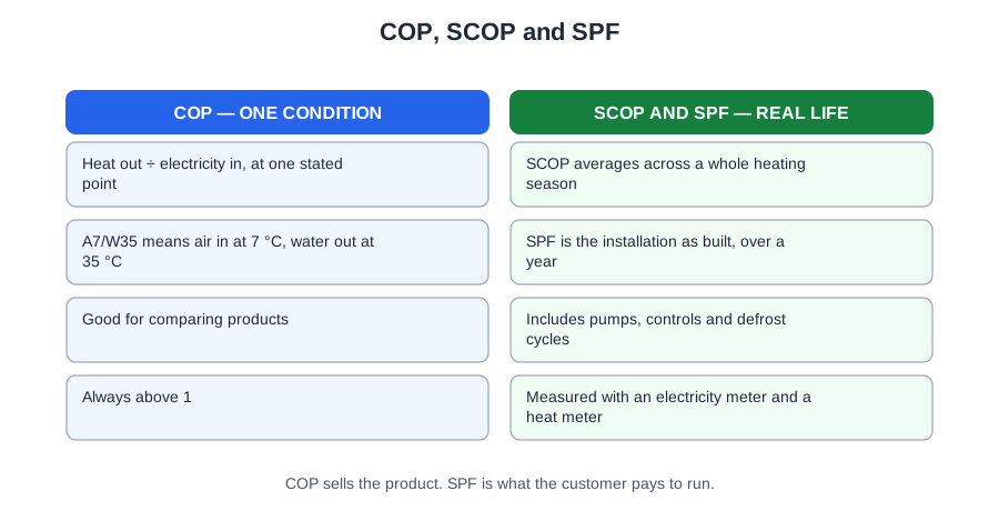
Three figures describe how well a heat pump performs, and they are not interchangeable. Manufacturers quote the flattering one; customers experience the honest one. Knowing which is which is the difference between selling a system that satisfies and one that generates complaints.
COP — a snapshot
Coefficient of performance is heat output divided by electrical input, at one stated set of conditions.
COP = heat output (kW) ÷ electrical input (kW)
A unit giving 9 kW while drawing 2.5 kW has a COP of 3.6 — sometimes written as 360% efficient. A working heat pump always has a COP above 1; if your answer comes out below 1, you have divided the wrong way round.
The catch is the conditions, and this is where a standard earns its keep. A quoted COP is measured at rating conditions specified in BS EN 14511, and is normally written in the form A7/W35 — 7 °C air in, 35 °C water out. Ground source uses B for brine, so B0/W35 is 0 °C brine in, 35 °C water out. A7/W35 tells a customer very little about a February morning at −2 °C with the system running at 50 °C, which is the condition they will actually remember.
SCOP — across a season
Seasonal coefficient of performance is calculated across a whole heating season and a spread of outdoor temperatures, with part-load testing and rating to BS EN 14825. It is far more realistic for comparing products, because it reflects how differently a unit behaves in October and in January.
SPF — the installation as built
Seasonal performance factor is total useful heat delivered divided by total electricity consumed by the whole system over a year, as installed. It counts the circulating pumps, the brine pump, defrost energy, any immersion top-up and cylinder standing losses.
SPF is normally lower than a headline COP, and it is the number that becomes the customer's bill. It is also the figure the installer most influences: two identical units in two identical houses can return very different SPFs, and the difference is design and commissioning, not the machine.
COP is a laboratory. SPF is a house. Always ask which one you are being shown.
The minimum figures the regulations actually require
Efficiency is not only a sales matter. The Domestic Building Services Compliance Guide sets recommended minimum standards for electrically driven heat pumps, measured at the BS EN 14511 rating conditions:
| Duty | New build | Existing build |
|---|---|---|
| Space heating (other than air-to-air) | COP 2.5 | COP 2.2 |
| Domestic hot water | COP 2.0 | |
| Air-to-air, space heating up to 12 kW | Seasonal COP ‘D’ rating for the median temperature range, to BS EN 14825 | |
Note how modest those minimums are compared with a 3.6 headline COP. They are a floor, not a target — and the gap between the floor and what a well-designed system actually achieves is the whole argument for doing the design properly.
The energy label
The ErP label puts products on a common footing, showing an efficiency class alongside rated output and sound power level. A package label can be produced for the system as installed, reflecting the heat pump and its controls together — which is a fairer representation of what the customer is buying than the unit label alone.
Temperature lift: the idea that decides everything
Knowing what the figures mean is one thing. Knowing what moves them is what makes you useful on site — and almost all of it comes down to one idea.
Temperature lift is the gap between the source temperature and the flow temperature delivered. A unit collecting at 2 °C and delivering at 45 °C has a lift of 43 K. The bigger the lift, the harder the compressor works for each kilowatt of heat, and the lower the efficiency.
As a working rule, every 1 °C taken off the flow temperature is worth roughly 2–2.5% in efficiency. Across a heating season that is a large number. Drop a design from 55 °C to 45 °C and you have bought yourself something in the order of a fifth better efficiency without changing the machine at all.
That single relationship explains why heat pump design pushes so hard towards underfloor heating and generously sized radiators — and why swapping a boiler for a heat pump on unchanged radiators performs so badly. The machine is not the problem. The lift is.
Why cold weather hurts twice
As outdoor temperature falls, an air source unit is hit from both directions at once:
- Colder air holds less available heat, so output falls.
- The gap to the flow temperature widens, so efficiency falls.
Both move the wrong way, precisely when the building needs most heat. A ground source unit largely escapes this. Its source sits at 8–12 °C all year, so the lift barely changes and performance stays steady through the coldest weeks.
Sizing: wrong in either direction
| What happens | Why it matters | |
|---|---|---|
| Oversized | Meets demand too quickly, reaches setpoint, stops, restarts minutes later | Short cycling wears the compressor and depresses seasonal efficiency. Heat pumps want to run long and low. |
| Undersized | Runs flat out in cold weather and still cannot hold temperature | Backup heat covers the shortfall — usually an immersion heater at a COP of 1, and the bills show it. |
Both faults trace back to the same root cause: an inadequate heat loss calculation. Oversizing is not a safety margin on a heat pump the way it is sometimes treated on a boiler.
Air source heat pumps
Heat pump names look confusing until you know the convention. It is always source-to-emitter: the first word is where the heat comes from, the second is what it is delivered into. Air-to-water takes heat from outside air and heats a wet system. Apply that rule and every name explains itself.
Monobloc or split
Both collect from outside air. The difference is where the refrigerant circuit lives, and it has a direct effect on who is legally allowed to do the work.
- Monobloc — the entire refrigerant circuit is sealed and factory-charged inside the outdoor unit. Only insulated flow and return water pipes enter the building. No refrigerant work on site, so no F-Gas qualification is needed for the connection. The trade-off is that water-filled pipework runs outdoors, which makes freeze protection critical.
- Split — the evaporator sits outside, the condenser and compressor indoors, joined by refrigerant lines run and charged on site. That is refrigerant circuit work, and it legally requires an F-Gas qualified operative.
The monobloc is by far the commoner domestic arrangement in the UK, largely because of that F-Gas simplification.
Air-to-air and exhaust air
Air-to-air delivers warm air through wall units or ducts. There is no wet system and no cylinder, so it cannot provide domestic hot water — which limits its use in a whole-house UK retrofit, though it is common in commercial and single-room applications.
Exhaust air units recover heat from ventilation air being extracted from the dwelling before it is discharged. The available energy is capped by the ventilation rate, so output is modest. These suit small, airtight, well-insulated properties such as flats.
Monobloc keeps the refrigerant outside and the F-Gas work off your job. Split does neither.
Ground source and system configurations
A closed loop circulates a sealed water and antifreeze mixture — usually called brine — through buried pipework, exchanging heat with the ground by conduction. There are four common arrangements.
| Collector | Typical yield | Notes |
|---|---|---|
| Horizontal trenches | About 10–40 W per m² of ground | Cheapest, but land-hungry — often two to three times the heated floor area. Laid around 1.2 m deep and always below the frost line. |
| Slinky coils | As above | Overlapped pipe in a trench: more pipe per metre of trench, so less digging. Saves trench length, not ground area. |
| Vertical boreholes | About 20–55 W per m of borehole | 100–150 mm diameter, 15–200 m deep, grouted, spaced at least 5 m apart. Small footprint, higher drilling cost. |
| Pond or lake loops | About 9 m² of water surface per kW | Weighted coils on the bed of open water, minimum 3 m depth. Quick and cheap where the water exists. |
An open loop abstracts groundwater, passes it through a heat exchanger and returns or discharges it. Thermally excellent, but it needs an abstraction licence from the environmental regulator.
Why depth matters
Near the surface the ground simply follows the air a few weeks behind. By about 4 m down that seasonal swing has gone: the temperature holds within roughly ±2 K of the annual average air temperature. Deeper still it settles close to the local mean — at 100 m, about 9 °C in the north of Scotland rising to 14 °C in southern England.
So the advantage of a borehole is not that the ground is warmer on average. It is that it does not fall away in January, exactly when the building wants most heat — which takes you straight back to lift.
How many heat sources?
- Monovalent — one heat source, sized to cover the full design peak heat loss with no supplementary heat at any outdoor temperature.
- Bivalent — the heat pump plus a second, different source. The bivalence point is the outdoor temperature below which that second source must contribute.
- Hybrid — a heat pump and boiler under one controller that chooses between them on outdoor conditions and relative running cost.
A trap worth knowing: two heat pumps working together are still monovalent. They are the same kind of source. Bivalent requires a second, different type.
Inverter or fixed speed
An inverter-driven unit varies compressor speed to match demand, so it throttles back instead of stopping — long continuous running, and the best seasonal efficiency. A fixed-speed unit has only full output or nothing, so in mild weather the surplus must be absorbed by the system water. That is why adequate system volume matters far more on a fixed-speed machine.
The numbers worth carrying into an exam
| Figure | Value |
|---|---|
| Absolute zero | −273 °C |
| Typical delivered heat per kW of electricity | 3–4 kW |
| COP rating conditions | BS EN 14511, written as A7/W35 (air) or B0/W35 (brine) |
| Seasonal figure, part-load testing | BS EN 14825 |
| Minimum COP, space heating | 2.5 new build / 2.2 existing |
| Minimum COP, domestic hot water | 2.0 |
| Value of 1 °C off the flow temperature | Roughly 2–2.5% efficiency |
| Ground temperature, 8–12 °C band | Steady all year at collector depth |
| Ground temperature at 100 m | 9 °C (N Scotland) to 14 °C (S England) |
| Worst frosting conditions | Damp weather, 0–6 °C |
| Minimum borehole spacing | 5 m |
Where this goes next
Module 1 is the foundation. Everything in the modules that follow is an application of temperature lift and the refrigerant cycle: system design is the business of getting the flow temperature down and the flow rate right; survey is finding out whether the building and the plot will allow it; commissioning is proving the machine is actually running at the conditions the design assumed.
If you take one thing from this article, take lift. Reduce the lift and everything improves — the same machine becomes a better machine, and it costs nothing but design.
📝 10-Question Mock Test
Click an option to see whether you got it right. Explanations appear instantly — no submitting at the end.
A boiler converts fuel into heat and can never exceed what it is given. A heat pump moves existing low-grade heat from outside and upgrades it, so the electricity buys the upgrade rather than the heat itself. Nothing is created from nothing — the energy was already in the air or the ground.
Temperature is not the same as heat. At 2 °C the air is roughly 275 K above absolute zero and holds a great deal of thermal energy. The heat pump does not need warm air — it needs air warmer than the liquid in its evaporator, which may be boiling at around −5 °C.
Squeeze, give, drop, take. The compressor raises pressure and temperature; the condenser gives up heat to the heating water; the expansion valve drops the pressure and so the boiling point; the evaporator takes heat from the source. The two heat exchangers always sit opposite one another.
Warming a fluid moves very little energy; boiling it moves a great deal. That is latent heat of vaporisation — the same reason steam scalds far worse than water at the same temperature. The state change is what lets a physically small evaporator pull useful heat out of cold air.
The coil must be below both freezing point and the dew point for frost to form. Very cold air is usually dry and has little moisture to deposit, so the worst case is damp weather around 0–6 °C. Every defrost sheds water, so it must drain freely rather than pooling and refreezing under the unit.
COP = heat output ÷ electrical input = 9 ÷ 2.5 = 3.6, sometimes written as 360% efficient. A working heat pump always has a COP above 1 — an answer below 1 means the division has been done the wrong way round.
A quoted COP is measured at standardised rating conditions specified in BS EN 14511. A is air and W is water, so A7/W35 is 7 °C air in, 35 °C water out. Ground source uses B for brine, giving B0/W35. It tells you very little about a February morning at −2 °C running at 50 °C.
Seasonal performance factor is total useful heat delivered divided by total electricity consumed by the whole installed system over a year. It includes the circulating pumps, brine pump, defrost energy, any immersion top-up and cylinder losses. Two identical units in two identical houses can return very different SPFs, and the difference is design and commissioning.
Around 2–2.5% per °C. Across a heating season that is a large number, and it is why heat pump design pushes so hard towards underfloor heating and generously sized emitters. It is also why fitting a heat pump to unchanged radiators performs so badly — the machine is fine, the lift is not.
Monovalent means one kind of heat source sized to cover the full design peak heat loss. Two heat pumps are still one kind of source. Bivalent requires a second, different type — and the bivalence point is the outdoor temperature below which that second source must contribute.
Take this further on the PlumbMate heat pumps course
This article covers Module 1 of a seven-module course written for people doing the work, not just passing a test. The PlumbMate heat pumps course takes the same material and drills it:
- 47 lessons across 7 modules — principles, system design, regulations, survey, installation, commissioning and fault finding.
- A 242-question bank with an explanation on every option, not just the right one, so a wrong answer teaches you something.
- Interactive tasks — size a ground array, read a pump curve, set a heat curve, work a heat loss, run a safe isolation.
- Key facts, flashcards and short-answer practice per lesson, with your wrong answers resurfacing until they stick.
If you found the efficiency section useful, Module 1 covers it in more depth still, and Module 2 puts it to work on real emitter and flow-rate design.