Module 1 established that temperature lift decides a heat pump's efficiency. Module 2 is where you do something about it. System design is the business of getting the flow temperature down and keeping it there — and every decision in this article, from the heat loss calculation to the last thermostat, is either helping that or fighting it.
This covers Module 2 of the PlumbMate heat pumps course: heat loss and design conditions, flow rate and ΔT, pumps and the duty point, emitter sizing at low temperature, system volume and buffers, cylinders, and controls. There is a 10-question mock test at the end.
Heat loss and design conditions
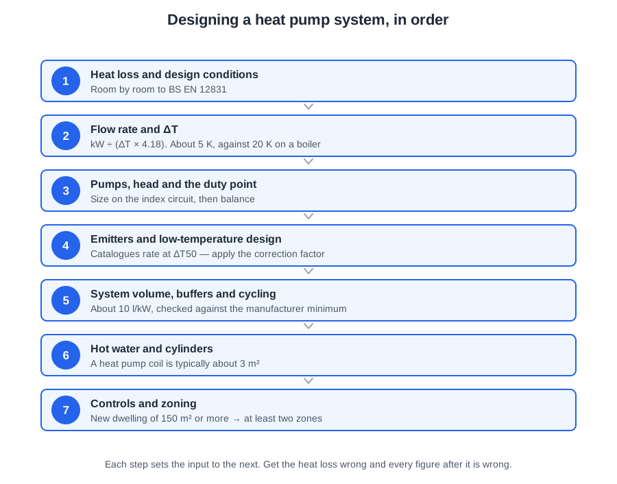
A heat loss calculation works out how fast a building loses heat when it is cold outside. That figure sizes the heat pump, sizes every emitter, and sets the flow temperature. Get it wrong and nothing downstream can be right. The method is set out in BS EN 12831.
Two ways heat escapes
Fabric loss is heat conducted out through every surface of the room — walls, roof or ceiling, floor, windows and doors — calculated surface by surface. That means the surfaces to cooler rooms and the party wall to next door, not only the outside ones:
fabric loss (W) = U × A × ΔT
where U is the U-value in W/m²K, A is the area in m², and ΔT is the temperature difference across that surface
For an external wall, ΔT is inside to outside. For a wall, floor or ceiling between two rooms it is the difference between them, and the same U × A × ΔT goes on both sheets: a loss (+) in the warmer room, a gain (−) in the cooler one. The room’s net load sizes its emitter, and you only credit a gain from a room the same system holds at its design temperature. For a party wall, take next door at 10 °C, because you cannot count on the neighbours heating it. A surface to a room at the same temperature still gets a line, at 0 K.
Ventilation loss is the energy needed to warm the outside air coming in, calculated from room volume, air change rate and the inside-to-outside temperature difference. Add the two together, room by room, and you have the building's heat loss.
Design conditions
The design external temperature is a regional figure, typically between −1 °C and −5 °C in the UK depending on location and altitude. It represents a cold but realistic winter condition. Designing for the coldest temperature ever recorded would grossly oversize the system for the rest of the season — and on a heat pump, oversizing is not a free safety margin.
Internal design temperatures vary by room: a living room is warmer than a hallway. Watch the arithmetic when the external figure is negative. At 21 °C inside and −2 °C outside, ΔT is 21 − (−2) = 23 K, not 19. That sign error is worth marks in an exam and worth kilowatts on site.
Solar gain and heat from appliances and occupants are deliberately excluded. The system has to hold temperature at night, in January, with nothing switched on.
Why it has to be room by room
A whole-house figure sizes the heat pump but tells you nothing about individual emitters. At a low flow temperature every radiator must be checked against its own room's loss. One undersized emitter forces the customer to raise the flow temperature for the whole house — wrecking the efficiency of every other room to fix one. That single sentence is the reason room-by-room is not optional on a heat pump job the way it is sometimes treated on a boiler swap.
Fabric first
Every kilowatt of heat loss removed by insulation is a kilowatt the heat pump never has to produce. Better fabric means a smaller unit, a lower flow temperature, lower capital cost and lower bills. It is almost always cheaper to remove a kilowatt of loss than to buy a kilowatt of heat pump.
Flow rate and ΔT
Heat is carried round a system by water. How much water you need depends on how much heat each litre is being asked to carry — and that is set by the temperature difference between flow and return.
flow rate (l/s) = kW ÷ (ΔT × 4.18)
The 4.18 is the specific heat capacity of water in kJ/kg·K — the energy needed to raise one kilogram of water by one degree. Work out the bracket first; that is where most errors creep in.
Worked example
A system has a load of 12 kW, flow at 45 °C and return at 40 °C.
- ΔT = 45 − 40 = 5 K
- flow = 12 ÷ (5 × 4.18) = 12 ÷ 20.9 = 0.57 l/s
Multiply by 3.6 for cubic metres per hour — about 2.07 m³/h. Pump curves are often printed in m³/h while design sheets use l/s, so check which the question wants before you answer it.
Why 5 K and not 20 K
Boiler systems are designed around a 20 K difference. A heat pump uses about 5 K, and the reason is the low flow temperature. With flow at 45 °C, a 20 K difference would return water at 25 °C — barely above room temperature, so the far end of every radiator would give off almost nothing. A narrow difference keeps the whole emitter usefully warm.
The consequence is that flow rate and ΔT are inversely proportional. Quarter the temperature difference and you quadruple the flow rate. That is why heat pump systems need larger pipework than the boiler system they replace, and why existing pipework must be checked rather than assumed.
Reading it backwards as a diagnostic
This relationship also works in reverse, and it is one of the most useful things on a service call. If a system designed at 5 K is measured at 10 K, the flow rate is roughly half what it should be. Look for a blocked filter, a closed valve or a pump set too slow. A wide temperature difference almost always means restricted flow.
Pumps, head and the duty point
Knowing the flow rate is only half the job. The pump also has to overcome the system's resistance, and those two numbers together decide which pump, at which speed, will do the work.
Head and the index circuit
Head is the resistance the pump must push against, measured in metres. It comes from the pipework, fittings, valves, emitters and heat exchangers on the hardest route through the system. That hardest route is the index circuit — the one with the greatest total resistance. Size the pump for the index circuit and every easier circuit is satisfied automatically.
The duty point
Plot the required flow rate along the bottom of a pump curve and the required head up the side. Where they cross is the duty point. Then choose the speed curve that passes on or above that point — a curve above it can deliver more than you need, so it will cope; a curve below it cannot. If every curve sits below the duty point, that pump is too small: select a different pump, or reduce the system's resistance.
Each curve slopes downwards from left to right, because the more water a pump moves, the less pressure it can generate. And again: 1 l/s is 3.6 m³/h.
Balancing
Once the pump is right, the flow still has to be shared out correctly. Water takes the easiest path, so without balancing the circuits nearest the pump take more than they need and the index circuit is starved. Balancing sets each circuit's flow to match its emitter's designed output, so rooms come up to temperature together and the system runs at its design ΔT.
Emitters and low-temperature design
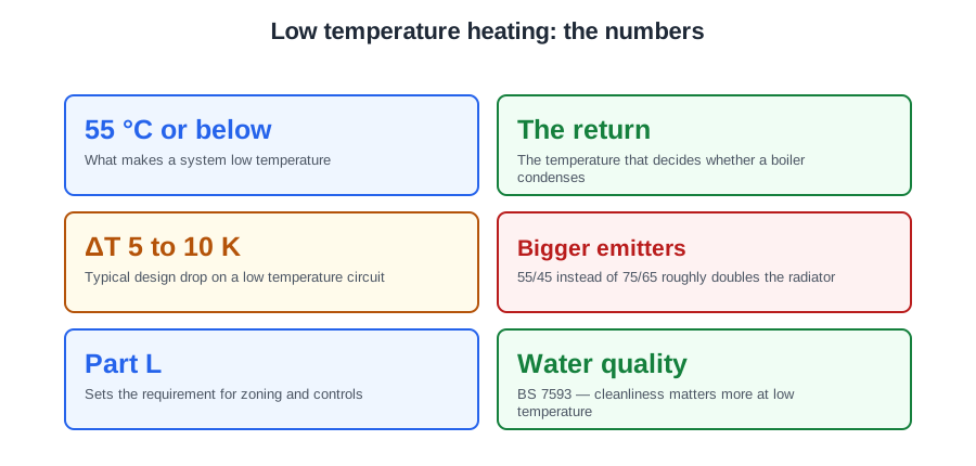
An emitter gives off heat because its surface is hotter than the room. The bigger that difference, the more heat it emits. Drop the flow temperature and the output falls away — which is the central problem of every heat pump retrofit.
Correction factors — and the commonest error in the trade
Radiator catalogue outputs are quoted at a standard temperature difference, traditionally ΔT50. Run the same radiator at roughly half that difference and it gives about half its rated output. The relationship is not linear — it follows a power curve with an exponent around 1.3 — so always use the manufacturer's correction factor for your actual design conditions.
catalogue output = room heat loss ÷ correction factor
A room losing 1000 W, with emitters achieving 50% of catalogue output, needs a radiator rated at 1000 ÷ 0.5 = 2000 W. Selecting a 1000 W radiator straight from the catalogue is the single commonest sizing error in retrofit work, and it is the error that ends with the customer turning the flow temperature up.
Emitters ranked by the temperature they need
| Emitter | Typical mean water temperature | Verdict |
|---|---|---|
| Underfloor heating | Around 35 °C | A whole floor of surface area. The best match. |
| Fan-assisted emitters | Low | Fan convectors move air across the coil, so useful output from a compact unit. |
| Oversized radiators | 45–55 °C | Workable if properly sized. |
| Standard boiler-sized radiators | 65 °C+ | Least suitable — they need temperatures that destroy the COP. |
Mixing underfloor with radiators
The two need different temperatures, so they cannot simply share one circuit. An underfloor control pack — a blending valve with its own pump — sits between the primary and the manifold, blending the flow down for the floor while the radiators run at the higher primary temperature.
System volume, buffers and cycling
A heat pump wants to run long and steady. It cycles when it produces more heat than the system can absorb — reaching setpoint, stopping, then restarting minutes later. Every start is a current surge and a burst of inefficient operation, so short cycling wears the compressor and depresses seasonal efficiency.
Volume is the cure
Water content is what absorbs surplus heat and lengthens each run. Manufacturers state a minimum system volume for each unit, quoted against a permitted number of starts per hour — usually somewhere between three and six. Tighter starts limit, longer minimum run, more volume required.
Count what the system already holds — pipework and emitters. A large underfloor system may satisfy the requirement on its own; a small, heavily zoned radiator system will not.
Three ways to add volume, and they are not equivalent
| Device | What it actually does |
|---|---|
| Volumiser | An insulated vessel plumbed in series, usually on the return. Everything flows through it, so there is no mixing penalty and the emitters get the full flow temperature. Where cycling is the only problem, often the better answer. |
| Buffer tank | Adds volume and can hydraulically separate the heat pump circuit from the emitter circuit. Also provides a reservoir of warm water for the defrost cycle. |
| Low loss header | Separates the circuits so they can run at different flow rates, but holds only a few litres. It solves a flow-matching problem, not a volume problem. |
Sizing a buffer
A common rule of thumb is around 10 litres per kW of output, but treat that only as a starting point. The real figure comes from the manufacturer's minimum system volume, less what the pipework and emitters already hold:
buffer = required total volume − emitter circuit volume
If the requirement is 215 litres and the emitter circuit holds 120, the buffer must be at least 95 litres.
A two-pipe buffer sits in series — simple, and no temperature blending. A four-pipe arrangement gives each side its own flow and return, providing full hydraulic separation at the cost of mixing inside the vessel, which can lower the temperature reaching the emitters. Zoning makes all of this more acute: as zones close, the volume in circulation falls, so a heavily zoned system needs volume that is always in circuit.
Hot water and cylinders
A boiler can supply a cylinder coil at 75 °C. A heat pump might manage 50 °C. That smaller temperature difference across the coil changes how the cylinder must be built and sized.
A much larger coil
Heat transfer depends on surface area and the temperature difference across it. With a far smaller difference available, the coil must be much larger — typically about 3 m² for a domestic cylinder. That is a typical figure, not a rule: MIS 3005-D says follow the heat pump and cylinder makers’ recommendations, and agree the reheat time with the customer. Connecting a heat pump to a standard boiler cylinder produces very long reheat times and pushes the customer onto the immersion heater, which runs at a COP of 1.
Cylinder volume follows demand: occupants, bathrooms, whether there is a bath or a high-flow shower. Heat pump cylinders are generally larger than their boiler equivalents, because water is stored cooler and reheats more slowly, so the store must carry the household through peak demand without the immersion cutting in.
How much larger? The arithmetic
“Generally larger” is not a design figure, and this one can be worked out. Nobody uses water at store temperature — it is blended down at the outlet — so what matters is how much blended water each litre of store can make:
Vblend = Vstore × (Tstore − Tcold) ÷ (Tblend − Tcold)
With a 10 °C cold main and water delivered at 40 °C, a litre of store at 60 °C makes 1.67 litres of blend. A litre at 50 °C makes 1.33.
| Store held at | Blend per litre stored | Volume needed, against 60 °C |
|---|---|---|
| 60 °C — boiler | 1.67 | × 1.00 |
| 55 °C | 1.50 | × 1.11 |
| 50 °C | 1.33 | × 1.25 |
| 45 °C | 1.17 | × 1.43 |
So a household a boiler would serve with 210 litres needs about 265 at 50 °C and about 300 at 45. That is where “generally larger” comes from — and it is a separate effect from the slow reheat. The coil is sized for the reheat rate; the volume for the storage temperature. A heat pump cylinder is not a boiler cylinder with a bigger coil.
Cylinder types
- Unvented cylinder — stores the domestic hot water itself at mains pressure. Falls under Building Regulations Part G.
- Thermal store — stores heated primary water; mains cold water passes through a heat exchanger and is heated on demand as it flows.
- Vented cylinder — fed from a cold water storage cistern.
Legionella and scalding — the two pull opposite ways
Heat pumps commonly store hot water at 45–52 °C for efficiency, which sits at the top of the range where legionella can proliferate and is too cool to kill it quickly. A periodic pasteurisation cycle — typically weekly — raises the full cylinder contents to 60 °C. The whole volume must reach temperature, not just the top.
That creates a scalding risk at the outlets, so a thermostatic mixing valve blends the stored water down to a safe delivery temperature. Store hot, deliver safe.
Bear in mind that pasteurisation usually runs on the immersion heater at a COP of 1, so an over-frequent or over-long cycle noticeably damages the system's SPF. It is a genuine trade-off between safety and efficiency, and it is settled in favour of safety.
Slow delivery to a distant outlet
Where hot water takes a long time to arrive, the cause is the volume of cooled water sitting in a long dead leg. On a heat pump, avoid a secondary circulation loop if you can: a store at 45 to 52 °C cannot bring a loop back at 50 °C. Shorten the run, move the cylinder nearer the outlets, or fit trace heating or a point-of-use heater at the far outlet.
If a loop cannot be avoided, fit a circulator and check valve, and insulate it throughout. How often you pasteurise is set by the risk assessment (MIS 3005-D). The loop sits below 50 °C all the time, so the risk assessment will usually call for more frequent pasteurisation than weekly: the whole store and the loop, with the loop pump running through the cycle, taken to 60 °C and typically held for about an hour, on an automatic timer. Record the regime in the risk assessment and the handover, and measure the temperatures at commissioning. A heat pump store with no loop keeps the weekly lift to 60 °C.
Controls and zoning
Heat pump controls do more than a boiler's timeclock and thermostat, because efficiency depends on how the system runs rather than simply whether it is on.
Weather compensation is the biggest lever you have
An outdoor sensor feeds a heat curve that sets the flow temperature against outdoor temperature: mild outside, low flow temperature; cold outside, higher. Since efficiency is governed by lift, running the lowest flow temperature that maintains comfort at any given moment is the single biggest control lever available.
Set the curve as low as comfort allows at commissioning, then review it in genuinely cold weather. A curve set high because it was a mild week rarely gets revisited, and the customer pays for it every winter.
Zoning — and what the regulations require
Approved Document L 2021 (paragraph 5.14) asks that a new dwelling with a floor area of 150 m² or more has at least two independently controlled heating circuits — in practice, each zone with its own time and temperature control. Two thermostats sharing one time channel does not satisfy this.
Paragraph 5.14 applies to new dwellings, and most heat pumps are retrofits. In an existing home, when a heat generator such as a boiler is replaced, paragraph 5.20 asks for thermostatic room controls in each room.
Zoning pulls against the heat pump's preference for a stable, open circuit, though. Every valve that closes reduces both the water in circulation and the surface available to give off heat. Heavily zoned systems therefore need volume that stays in circuit whatever the zones are doing — which takes you straight back to the buffer question.
Valves, and the trouble with TRVs
- Two-port motorised valve — opens or closes one zone on that zone's own demand.
- Diverter valve — switches between heating and hot water, usually with hot water taking priority.
Thermostatic radiator valves throughout a heat pump system progressively shut emitters off, cutting volume and flow and driving cycling. Common practice is to leave the reference room without a TRV, so there is always an open path, and to rely on weather compensation rather than local throttling.
Customer habits matter as much as hardware. Someone used to a boiler will switch the system off overnight and turn the flow temperature up when they feel cold. Both work against a heat pump — which is why the handover conversation is part of the control strategy, not an afterthought.
Boilers are controlled by switching off. Heat pumps are controlled by running lower.
The numbers worth carrying into an exam
| Figure | Value |
|---|---|
| Fabric loss | U × A × ΔT |
| Heat loss method | BS EN 12831 |
| Design external temperature (UK) | −1 °C to −5 °C, regional |
| Flow rate | kW ÷ (ΔT × 4.18) |
| Specific heat capacity of water | 4.18 kJ/kg·K |
| Heat pump design ΔT | About 5 K (boiler: 20 K) |
| Unit conversion | 1 l/s = 3.6 m³/h |
| Radiator catalogue rating | ΔT50; use the correction factor |
| Emitter sizing | room heat loss ÷ correction factor |
| Underfloor mean water temperature | Around 35 °C |
| Buffer rule of thumb | About 10 l/kW — check against the manufacturer's minimum |
| Heat pump cylinder coil | Typically about 3 m²; follow the heat pump and cylinder makers (MIS 3005-D) |
| Pasteurisation | Full contents to 60 °C, typically weekly |
| Zoning threshold | New dwelling of 150 m² or more → at least two independently controlled circuits (Approved Document L 5.14) |
Where this goes next
Design tells you what the system should be. Module 4, the survey, is where you find out whether the building and the plot will actually allow it — and Module 3 covers the regulations that constrain both. If any of the emitter or flow-rate arithmetic here felt shaky, the course has interactive tasks for exactly those: heat loss, emitter sizing, pump curves and ΔT.
📝 10-Question Mock Test
Click an option to see whether you got it right. Explanations appear instantly — no submitting at the end.
For an external surface, ΔT is the difference between inside and outside: 21 − (−2) = 23 K. Subtracting a negative adds. Getting the sign wrong here undersizes every emitter in the room by about 17%, and it is one of the most common arithmetic slips in the whole subject.
The total sizes the unit; the individual rooms size the emitters. At a low flow temperature every emitter has to be checked against its own room's loss, because a single undersized radiator makes the customer raise the flow temperature — wrecking the efficiency of every other room to fix one.
ΔT = 45 − 40 = 5 K. Flow = kW ÷ (ΔT × 4.18) = 12 ÷ (5 × 4.18) = 12 ÷ 20.9 = 0.57 l/s. Work the bracket out first — 20.9 is the intermediate figure, not the answer.
It follows from the low flow temperature. A narrow difference keeps the whole emitter usefully warm. Note the consequence runs the opposite way to option C: flow rate and ΔT are inversely proportional, so a narrow ΔT means a higher flow rate and larger pipework, not smaller.
Flow rate and ΔT are inversely proportional, so double the ΔT means about half the flow. A wide measured temperature difference almost always means restricted flow, and it is one of the most useful quick diagnostics on a service call.
A curve on or above the duty point can deliver at least what you need, so it will cope. A curve below it cannot, no matter how it is set up. If every curve sits below the duty point the pump is too small — choose another, or reduce the system's resistance.
catalogue output = room heat loss ÷ correction factor = 1000 ÷ 0.5 = 2000 W. Taking the 1000 W figure straight from the catalogue is the commonest sizing error in retrofit work, and it is the error that ends with the customer turning the flow temperature up.
buffer = required total volume − emitter circuit volume = 215 − 120 = 95 litres. Always count what the system already holds first: a large underfloor system may satisfy the manufacturer's minimum on its own and need no buffer at all.
Everything flows through a volumiser, so the emitters still receive the full flow temperature. A four-pipe buffer gives hydraulic separation but mixes inside the vessel, which can lower the temperature reaching the emitters. A low loss header holds only a few litres — it solves a flow-matching problem, not a volume problem.
Heat transfer depends on surface area and the temperature difference across it. A boiler supplies a coil at around 75 °C; a heat pump might manage 50 °C. With far less difference available, the area has to make up the shortfall. Fit a heat pump to a standard boiler cylinder and you get very long reheat times and a customer living on the immersion. The exact size comes from the heat pump and cylinder makers, as MIS 3005-D requires.
Practise this on the PlumbMate heat pumps course
System design is the module where arithmetic mistakes are expensive, so the heat pumps course makes you do it rather than read about it:
- Interactive tasks — work a room-by-room heat loss, size an emitter with a correction factor, read a pump curve to a duty point, and set a ΔT.
- 42 questions on Module 2 alone, with an explanation on every option so a wrong answer teaches you something.
- Key facts and flashcards per lesson, with your wrong answers resurfacing until they stick.