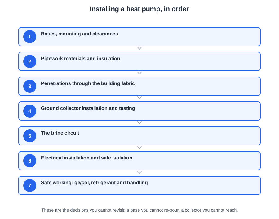
Installation is where the design either survives contact with the building or quietly gets compromised. Most of what follows is about decisions you cannot revisit: a base you cannot re-pour with a unit on it, a collector you cannot reach once the trench is closed, a penetration you cannot inspect once it is plastered over.
This covers Module 5 of the PlumbMate heat pumps course: bases and clearances, pipework and insulation, penetrations, laying and testing a ground collector, the brine circuit, safe isolation, and handling glycol and refrigerant safely. There is a 10-question mock test at the end.
Bases, mounting and clearances
The base
An outdoor unit needs a stable, durable base that resists vibration and will not settle. The correct method is a poured concrete slab, 100 mm thick, on a compacted sub-base, extending far enough to support the unit's full footprint.
That 100 mm figure is the one to remember. It is enough mass to damp compressor vibration and enough depth to spread the load without settling. Always check the manufacturer's own base requirement as well — some larger units call for more.
The common shortcuts all fail for the same reason: they lack mass and stability. Timber flexes, resonates and rots outdoors, amplifying vibration rather than damping it. Existing patio slabs are bedded on sand and were never laid to carry a point load, so they settle unevenly. Loose gravel cannot hold the unit level at all.
Why level matters more than it looks
The condensate tray and its drain are designed around the unit sitting level. Out of level, water pools in the tray, escapes where it should not, or refreezes in the wrong place. An unlevel unit also loads the internal compressor mountings unevenly, increasing vibration and wear. Check it with a spirit level at installation, not by eye.
Clearances
Minimum clearances are model-specific and stated by the manufacturer. They serve two purposes: unrestricted airflow to and from the coil, and physical access for servicing. Clearances differ front, rear and sides — do not apply one figure all round.
Reducing them degrades output, because the unit begins to recirculate its own cold discharge air and the source temperature it sees drops below the true outdoor temperature. The machine is then working at a bigger lift than the weather justifies, entirely because of where it was put.
Mass, level, clearance. A unit that is heavy-mounted, level and able to breathe will give no trouble on any of the three.
Pipework materials and insulation
Barrier pipe is not negotiable
Plastic pipe on a heating circuit must be barrier pipe — pipe with an oxygen barrier layer built into its wall. Ordinary plastic pipe is permeable to oxygen, which diffuses continuously into the system water.
That oxygen corrodes every ferrous component in the system: steel radiators, pump bodies, the heat exchanger. The resulting magnetite sludge settles in emitters and blocks the plate heat exchanger, whose narrow waterways clog far more readily than a boiler's. The damage is slow, invisible and expensive. Check the pipe marking before you install it.
Copper is entirely suitable. What matters is that pipework is correctly sized for the higher flow rates a heat pump needs — not the material.
Closed-cell insulation outdoors
External pipework must be insulated with closed-cell foam. Its sealed cell structure does not absorb water, so it keeps its insulating value outdoors and does not trap moisture against the pipe.
Open-cell foam, fibreglass and mineral wool all behave like sponges. Once saturated they lose most of their performance and hold water against the pipe surface, which invites corrosion. They are internal materials.
Two requirements people forget:
- Protection. Sunlight breaks foam insulation down within a season or two unless it is UV-stable or clad. It also needs protecting anywhere it can be knocked or stood on.
- Continuity. Insulation must be continuous, including at valves, fittings and supports. A bare valve body or a gap at a bracket becomes a concentrated heat loss — and on external pipework, a freezing point.
The monobloc freeze risk
On a monobloc, no refrigerant leaves the outdoor unit — it is water that runs between the unit and the building. That water is exposed to sub-zero temperatures, and if the system stops for a power cut, a fault or a holiday, it can freeze and split the pipework. Insulation, routing and any manufacturer-specified freeze protection are critical rather than cosmetic. It is the price paid for keeping the F-Gas work off the job.
Penetrations through the building fabric
Every time pipework or cable passes through the fabric, three Parts of the Building Regulations are engaged at once. Getting one right and forgetting the others is the usual failure.
| Part | Question to ask | What it requires |
|---|---|---|
| A | Have I weakened the structure? | Forming the opening must not compromise structural integrity. Core drilling through a lintel is a genuine risk given the hole size a heat pump's primary pipework needs. |
| B | Have I breached a fire compartment? | Proprietary fire stopping restoring the element's resistance. Plastic pipe needs an intumescent collar that collapses the pipe as it softens; copper does not. |
| C | Can water get in? | Sleeve the pipe, make good and weatherproof. Expanding foam alone is not a weatherproof finish — it degrades under UV and offers the pipe no protection. |
The pipe is sleeved so it can move with thermal expansion without abrading against the masonry and is not bonded into the structure. Fall the sleeve slightly outward where practical.
Where the collector enters
A ground collector entry is below ground, so it is a water ingress risk and must be sealed watertight. Once inside, the brine is at low temperature — often below the dew point — so uninsulated pipework will attract condensation, drip, and cause damp and corrosion. Sleeve and seal outside; insulate with closed-cell material inside.
Structure, fire, weather. Ask all three questions at every penetration.
Ground collector installation and testing
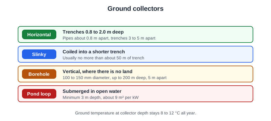
Everything here follows from one fact: once the trench is backfilled, reaching the pipework again means excavating the array. Every decision is about not needing to.
Depth, bedding and spacing
Horizontal collectors are laid at around 1.2 metres — below the frost line and below the zone affected by seasonal surface temperature swings, but shallow enough that the ground recharges from the surface each summer.
Bed the pipe in material free from sharp stones. A stone bearing against the pipe under the weight of backfill can abrade or puncture it over time, and a leak in a buried collector means losing brine, losing performance, and digging to find it. Sand or fine soil surround is cheap insurance.
Pipes must be laid at their designed centres. Bundling runs together to save trench space means adjacent pipes draw heat from the same ground, so extraction per metre collapses and the array underperforms from day one.
Joints
The best buried joint is no joint at all — collector pipe comes in long coils for exactly this reason. Where a joint is unavoidable it must be made by electrofusion, not by mechanical means. Compression fittings rely on a seal that can relax over time, and a buried mechanical joint is a future leak you cannot inspect.
The manifold is the only diagnostic point a buried array will ever have
Where the array has multiple circuits, they come together at a manifold with isolation valves and flow measurement for each circuit, housed somewhere accessible. Without individual isolation, a leak in one loop means losing the whole array. Without flow measurement, there is no way to confirm each loop is contributing.
Test before backfill, hold pressure during it, and put the manifold somewhere you can actually reach.
The brine circuit
The brine circuit is the sealed loop carrying a water and antifreeze mixture between the ground collector and the heat pump's evaporator. It is a third circuit, separate from both the heating primary and the refrigerant circuit.
The brine circulator is a parasitic load
A dedicated circulator moves the mixture around the array and through the evaporator. Its electrical consumption counts against the system's SPF, which is why collector resistance and pump sizing matter rather than being an afterthought. On a ground source system this is the third pump, alongside the heating circulator and any cylinder primary pump.
Antifreeze concentration — measure it, do not calculate it
Brine leaving the evaporator routinely runs below 0 °C. That is normal operation, not a fault. The mixture must therefore give freeze protection comfortably below the lowest temperature expected in service, because ice forming in the evaporator would damage the heat exchanger.
Verify the concentration by measuring the mixture with a refractometer or hydrometer, not by calculating from what went in. Residual water in the array, incomplete mixing or a part-used container all shift the result. Record the figure.
Purging the air
A collector array is hundreds of metres of pipe with long horizontal runs and no natural high point where air will gather. Automatic air vents cannot reach air trapped mid-array. The only method that works is circulating at high velocity using a powered flushing rig, fast enough to entrain air pockets and carry them back to the fill vessel.
Trapped air blocks flow through parts of the array, so extraction falls and the unit may go to low-temperature lockout. It also causes the circulator to lose prime.
Record the pressure
Note and record the brine circuit pressure at commissioning. A buried collector cannot be inspected, so that recorded figure is the only baseline against which a future engineer can recognise a slow loss — which on a sealed loop means a leak in the array.
Electrical installation and safe isolation
BS 7671, the IET Wiring Regulations, sets the technical requirements: cable sizing, protective devices, earthing and bonding, RCD protection and the inspection and test procedures. Part P of the Building Regulations creates the legal duty; BS 7671 describes how to satisfy it.
A heat pump needs its own dedicated circuit, correctly rated and protected. A plug and socket is unsuitable for a fixed appliance of this load, and starting current matters as much as running current when sizing — particularly on a fixed-speed unit.
Means of isolation
An engineer working on the unit must be able to isolate it locally, see that it is isolated, and lock it off. So the isolator must be accessible, adjacent to the unit, and capable of being secured in the off position. A remote isolator that cannot be secured leaves the operative depending on nobody else touching it while they work — which is not a safety measure.
The seven steps
- Check that it is safe and acceptable to isolate, and identify the circuit.
- Isolate.
- Secure the isolation — lock off a breaker, or remove the fuse and retain it in your own pocket.
- Label the point of isolation.
- Prove the voltage indicator on a known live source.
- Test dead — line to earth, line to neutral, and neutral to earth.
- Re-prove the indicator on a known live source.
Step 3 is a branch, not a sequence. You cannot lock off a fuse, and you cannot put an MCB in your pocket — you do whichever the device allows, and only one of them. Note also that securing happens at the moment of isolation, before testing dead. Some textbooks show a six-step version that locks off afterwards; the NICEIC order is the one to follow.
Step 4 is the one most often dropped. A label tells anyone else on site why the circuit is off and who to speak to before restoring it — the key in your pocket does not.
Step 7 catches a tester which failed during the test. Without it, a faulty indicator reads dead on a live circuit and you have proved nothing. Never use a neon screwdriver as a voltage indicator.
When testing between earth and a live terminal, touch the earth probe first, so the other probe cannot become live in your hand. And heat pumps contain components that hold a charge after isolation — follow the manufacturer's stated discharge time before touching anything internal.
Prove, test, prove. Three steps, never two — and the isolator must be lockable.
Safe working: glycol, refrigerant and handling
Glycol
Glycol is a hazardous substance under COSHH. Consult the safety data sheet for the specific product — different products have different hazard profiles — and wear the PPE it identifies, including eye protection. Splashes to the eye are a real risk when filling and purging under pressure.
If it spills: contain, protect, absorb, dispose. Contain first so it cannot spread or reach a drain, put on the PPE, absorb with a suitable absorbent, and dispose of the contaminated material through the proper waste route. Never flush a spill with water — that spreads it and washes it into drains, which is an environmental offence. Glycol is also extremely slippery, so a spill is an immediate slip hazard.
Never decant into unmarked containers. And note that ethylene glycol is considerably more toxic if ingested than the propylene glycol usually specified for heat pump circuits.
Refrigerant — two distinct hazards
- Freeze burns. Liquid refrigerant escaping to atmosphere evaporates almost instantly, drawing heat from whatever it touches. Skin and eyes are both at risk. Very cold brine and evaporator surfaces present a lesser version of the same hazard.
- Toxic gases. Refrigerants decompose when heated, producing highly toxic and corrosive breakdown products. Never apply heat or a flame to a circuit that has not been properly recovered. Brazing also produces fume from the filler and flux, so ventilation and respiratory protection are needed.
Refrigerants are heavier than air and can displace oxygen in a confined or low-lying space, causing asphyxiation without warning.
Handling, cuts and eyes
The manual handling hierarchy is avoid, assess, reduce. Outdoor units, filled cylinders and drums of glycol are heavy and awkward, and are frequently handled through restricted access — the classic back injury scenario.
The thin aluminium fins of an evaporator coil are sharp enough to cut through a light glove, and pressed sheet metal casing edges cut readily, so wear the right gloves whenever panels come off. Resin anchor fixings require eye protection: the resin is an irritant dispensed under pressure, and drilling the holes throws up dust and debris.
The numbers worth carrying into an exam
| Item | Detail |
|---|---|
| Concrete base | 100 mm thick, on a compacted sub-base |
| Horizontal collector depth | Around 1.2 m |
| Buried collector joints | Electrofusion — never mechanical |
| Plastic heating pipe | Oxygen barrier pipe only |
| External insulation | Closed-cell, UV-protected, continuous |
| Penetrations | Part A structure, Part B fire, Part C weather |
| Brine concentration | Measured with a refractometer or hydrometer, and recorded |
| Collector purging | High velocity, powered flushing rig |
| Electrical supply | Dedicated circuit; lockable isolator adjacent to the unit |
| Safe isolation | Seven steps; secure before testing dead; prove, test, prove |
| Glycol spill | Contain, protect, absorb, dispose — never flush with water |
Where this goes next
The system is in. Module 6 is proving it works and leaving the customer able to use it — cleaning and flushing, filling, setting the flow rate and ΔT, the heat curve, and the records that settle any later dispute.
📝 10-Question Mock Test
Click an option to see whether you got it right. Explanations appear instantly — no submitting at the end.
100 mm of poured concrete gives the mass to damp compressor vibration and the depth to spread the load without settling. The alternatives all fail for the same reason — they lack mass and stability. Timber flexes and resonates, sand-bedded slabs settle unevenly under a point load, and gravel cannot hold the unit level at all.
It re-ingests air it has already chilled, so it is effectively working from a colder source than the weather provides — a bigger lift, entirely because of where it was put. Note also that clearances differ front, rear and sides, so one figure all round is wrong.
Ordinary plastic pipe is permeable to oxygen. The oxygen corrodes steel radiators, pump bodies and the heat exchanger, and the resulting magnetite blocks a plate heat exchanger far more readily than it would a boiler, because the waterways are much narrower. The damage is slow, invisible and expensive.
Open-cell foam, fibreglass and mineral wool behave like sponges: once saturated they lose most of their performance and hold water against the pipe, inviting corrosion. Note that closed-cell foam still needs UV protection or cladding — sunlight breaks it down within a season or two.
An unsealed service penetration is a direct route for fire and smoke between compartments. Plastic needs an intumescent collar, because the pipe itself will soften and leave an opening; copper does not. Expanding foam is neither fire stopping nor a weatherproof finish.
Mechanical joints rely on a seal that can relax over time, and a buried mechanical joint is a future leak you cannot inspect. Electrofusion produces a homogeneous joint in the pipe material. Better still is no joint at all, which is why collector pipe comes in long coils.
Once the trench is backfilled the pipework is unreachable. Without individual isolation, a leak in one loop means losing the whole array; without flow measurement, there is no way to confirm each loop is contributing. It is the only diagnostic point the system will ever have.
Residual water in the array, incomplete mixing or a part-used container all shift the result away from what the arithmetic predicts, so the mixture must be measured rather than calculated. Note also that brine leaving the evaporator routinely runs below 0 °C — that is normal operation, not a fault.
Air trapped mid-array has nowhere to rise to, so a vent cannot reach it. The only method that works is circulating at high velocity with a powered flushing rig, fast enough to entrain the air pockets and carry them back to the fill vessel. Trapped air blocks flow, cuts extraction and can cause the circulator to lose prime.
Labelling disappears from a lot of accounts of the procedure. It is what tells anyone else on site why the circuit is off and who to speak to before restoring it. The other commonly dropped step is the final re-prove, which is what catches a tester that failed during the test itself.
Practise this on the PlumbMate heat pumps course
Installation is the module where a mistake is buried, plastered over or bolted down before anyone notices. The heat pumps course covers it with:
- An interactive safe isolation task that makes you order the seven steps correctly — including the two most often dropped.
- 32 questions on Module 5, with an explanation on every option.
- Key facts and flashcards per lesson, so the figures that matter on site are the ones that stick.