The survey is where a heat pump job is won or lost. Every problem found here costs a phone call; the same problem found on installation day costs a return visit, and some of them cannot be corrected at all once the system is in. This is the module that decides whether the design in Module 2 can actually be built on this property.
This covers Module 4 of the PlumbMate heat pumps course: the pre-installation checklist, selecting the unit from manufacturer's data, sizing a ground array, siting and noise, the electrical supply and structure, and assessing an existing system. There is a 10-question mock test at the end.
The pre-installation checklist
The checklist forces every prerequisite to be checked and recorded before work begins. It is not a formality — it produces a genuine decision, proceed or not, recorded with reasons. The headings group into four questions:
- Am I authorised? Planning permission or confirmation of permitted development, the building control route, and the installation contract.
- Is the equipment right? The unit's rating against the emitter circuit load, the collector circuit against the heat pump rating on a ground source system, and the buffer size.
- Will it physically go in? Siting of the unit, siting of internal components, structural suitability, and access to all work areas.
- Are the services there? A suitable electrical input service for the heat pump and its controls.
One failure stops the job
If a single item fails, the installation cannot proceed as specified. Record the failure with its reasons and the calculation behind it, revise the design — a larger buffer, a different collector arrangement, a supply upgrade — then re-check the item.
Proceeding and fixing it afterwards is not an option. Some failures cannot be corrected once the installation is complete, and noting a known defect in the handover pack is not a resolution.
Record, revise, re-check, then proceed.
Selecting the unit from manufacturer's data
Manufacturers publish output at several sets of conditions, and the figures differ substantially between them. Selecting from the wrong row quietly undersizes the installation.
Read the condition notation first
- A7/W35 — air source: 7 °C air in, 35 °C water out.
- B0/W45 — brine at 0 °C in, 45 °C water out. Ground source units use B for brine.
A unit quoted at 8.9 kW at B0/W35 might give only 8.6 kW at B0/W45, because a greater lift means less output and a lower COP. Find the row matching your design flow temperature before comparing anything.
Closest fit above the load
Suppose the design peak heat loss is 8 kW at a design flow temperature of 45 °C, and three units offer 6.2 kW, 8.4 kW and 10.5 kW at that condition. The 8.4 kW unit is correct: it is the smallest that meets the load.
- The 6.2 kW unit cannot meet the load — the property will not hold temperature at design conditions.
- The 10.5 kW unit is 30% oversized. Oversizing is not a safety margin on a heat pump; it causes short cycling and depresses seasonal efficiency.
What the data supplies, and what it does not
Manufacturer's documentation gives everything specific to the machine: outputs at stated conditions, electrical characteristics and starting current, sound power level, required clearances, minimum system volume, permitted starts per hour, and nominal flow rate.
It knows nothing about the property. The design external temperature comes from published regional climate data, and the room-by-room heat losses come from your own survey and calculation. Keep the two sources clear in your head — exam questions test exactly that boundary.
Sizing a ground array
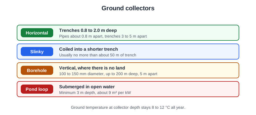
A ground array is sized in three steps, plus a fourth that is easy to forget.
Step one: deduct the compressor
The ground does not supply the whole output. The compressor's electrical input becomes heat in the system too, so only the difference has to come from the ground.
ground extraction = output − electrical input
A 9 kW unit at a COP of 4 draws 9 ÷ 4 = 2.25 kW, so extraction is 9 − 2.25 = 6.75 kW. Sizing on the full 9 kW would make the array a third larger than necessary — several hundred metres of unnecessary trenching.
Step two: divide by the yield
collector length = extraction (W) ÷ extraction rate (W/m)
At 20 W/m: 6750 ÷ 20 = 338 m of pipe.
The extraction rate depends on two things. Ground conditions — wet, dense soils conduct well and support high rates; dry sandy ground supports far less. And the annual run hours, expressed as FLEQ (full load equivalent hours): a system running 2400 FLEQ hours draws far more from the ground over a season than one running 1200, so the permissible rate per metre is lower and the array must be longer.
For a rough sense of scale, a horizontal array yields somewhere around 10–40 W per m² of ground, and a vertical borehole around 20–55 W per metre of borehole. Use those as a sanity check, not as design figures — the number you size on comes from the array designer or the software.
Step three: split it into loops
That 338 m is the total pipe, not one continuous run. Push it all through a single circuit and the pressure drop defeats the circulator, so the array is divided into several equal loops brought back to a manifold. Equal is the important word: identical lengths take a fair share of the flow on their own, whereas unequal ones need balancing you can no longer reach once the trench is backfilled.
As a working guide, a loop runs to about 100 m in 25 mm pipe, rising to about 400 m in 40 mm. In 25 mm, 338 m becomes four circuits of roughly 85 m.
Step four: check it fits
At 1 metre centres, each metre of pipe occupies a metre-wide strip one metre long — so the area in square metres equals the pipe length in metres. 340 m of pipe needs 340 m². Compare that against the genuinely usable area, remembering the array must clear buildings, drains, trees and boundaries.
If it does not fit, the check fails and the design must change: vertical boreholes instead of horizontal, or a reduced load through fabric improvement. If the answer is boreholes, the shape of the job changes — typically 100–150 mm diameter, drilled between 15 and 200 m, grouted, and spaced at least 5 m apart. Any closer and neighbouring boreholes draw on the same rock.
Where there is open water on the plot, a pond or lake loop is worth assessing: reckon on at least 3 m of depth and roughly 9 m² of water surface per kW.
Two ways undersizing bites
There is no tolerance to apply here. An undersized array progressively depletes the ground, so performance degrades over seasons rather than failing immediately — which makes it a particularly unpleasant fault to inherit. Nor can you recover a shortfall by tightening the centres: adjacent pipes then draw on the same ground and the rate per metre falls.
The faster failure is frost heave. Draw heat out faster than the ground can replace it and the soil around the pipe freezes, expands and lifts — taking the pipe, and whatever is laid over it, with it. That is why depth is specified as well as length: practice puts a trench at around 1.2 m, CIBSE gives a range of 0.8–2.0 m and prefers at least 1.5 m where the ground allows, and the local frost line is the floor rather than the target.
Siting and noise
Three factors, none of them aesthetic
- Airflow. The unit must breathe. Restricted airflow, or recirculation of its own cold discharge air, collapses output. Manufacturer's clearances differ on each face — do not apply one figure all round.
- Meltwater drainage. Every defrost sheds water. If it cannot drain freely it pools, freezes, builds up into the base of the unit and makes any adjacent path hazardous.
- Neighbours. The noise assessment position is at the nearest habitable room window of a neighbouring property, so where those windows are shapes the siting more than anything else.
Structure-borne noise is the one that generates complaints
Noise travelling through the building fabric is far more troublesome than airborne noise, and it is the usual cause of complaints from inside the dwelling. Two measures break the path:
- Anti-vibration mounts or an isolated base, so vibration does not pass into the structure at the mounting.
- Flexible connections between the unit and rigid pipework. Rigid pipe bolted straight to the unit carries compressor vibration into every wall it passes through.
A lightweight timber-framed wall acts as a sounding board and is among the worst mounting positions available.
Siting a ground source unit indoors
Ground source units usually go in a garage, utility room or outbuilding. Check five things: the unit's dimensions, its weight against the floor, the manufacturer's clearances, whether compressor noise will transmit into living space, and whether it can be reached for service. A habitable room is generally the worst choice.
Electrical supply, structure and access
The electrical input service
Establish on the survey whether the supply can carry the additional load, including starting current — which matters as much as running current, particularly on a fixed-speed unit. Check whether the supply is single or three phase, the main fuse rating, and whether the consumer unit has capacity for a dedicated circuit. The installation must also have proper means of isolation with a correctly rated protective device.
Settle the DNO position here too, not the week before installation. A connection needing prior approval or network reinforcement can take weeks.
Structural suitability
Three loads to think about. A filled cylinder is a substantial point load, and one on an upper floor is the case most often overlooked. A wall-mounted unit imposes load on the wall. And forming openings for pipework can affect structural elements — core drilling through a lintel is a real risk on these jobs.
Access, in three dimensions
- Getting plant in — the route from the road to the final position, for heavy and awkward items.
- Pipe runs — routes between the unit, cylinder and emitters.
- Future servicing — the one most often forgotten, and it causes trouble for years. A cylinder that can only be installed by removing a door frame is a problem best identified on the survey.
Assessing the existing system
On a retrofit, five checks decide how much of the existing installation survives — and the last one is not optional.
Emitters
The decisive question is whether each existing emitter can deliver its own room's heat loss at the design flow temperature. That means applying the manufacturer's correction factor room by room, not judging the system as a whole. This is the check that catches the retrofit where nobody upsized the radiators.
Pipework
A boiler system designed around a 20 K temperature difference carries roughly a quarter of the flow a heat pump system at 5 K needs for the same load. Undersized pipework produces excessive velocity, noise and pressure drop, and may make the design flow rate unachievable. Check the index circuit in particular. Material matters less than size: copper is fine, and plastic must be oxygen-barrier pipe.
Condition
Years of magnetite sludge in an existing system will find its way to the heat pump's plate heat exchanger, which has far narrower waterways than a boiler's. The system will need thorough cleaning, treatment and in-line filtration before commissioning — plan for it rather than discovering it.
The cylinder
An existing boiler cylinder will almost certainly have too small a coil. With only 50 °C available instead of 75 °C, the heat transfer surface must be much larger — typically about 3 m², following the heat pump and cylinder makers (MIS 3005-D). Reusing a boiler cylinder produces very long reheat times and pushes the customer onto the immersion heater.
The customer
Discuss how the system will run at survey stage, not at handover. Someone used to a boiler expects rapid, hot bursts of heat and expects to switch the system off when out. A heat pump behaves quite differently, and a customer who has not been prepared for that will read normal operation as a fault.
Setting the expectation early prevents complaints that cannot be resolved technically, because there is nothing wrong with the system.
The numbers worth carrying into an exam
| Figure | Value |
|---|---|
| Ground extraction | output − electrical input |
| Collector length | extraction (W) ÷ extraction rate (W/m) |
| Buffer | required total volume − emitter circuit volume |
| Horizontal yield (sanity check) | 10–40 W/m² of ground |
| Borehole yield (sanity check) | 20–55 W/m of borehole |
| Loop length | About 100 m in 25 mm; about 400 m in 40 mm |
| Borehole | 100–150 mm diameter, 15–200 m deep, spaced ≥5 m |
| Pond loop | ≥3 m depth, about 9 m² surface per kW |
| Trench depth | Around 1.2 m; CIBSE 0.8–2.0 m, preferring 1.5 m |
| Horizontal area at 1 m centres | Area in m² equals pipe length in m |
| Heat pump cylinder coil | Typically about 3 m² (follow the makers) |
| Boiler pipework at 20 K vs heat pump at 5 K | About a quarter of the flow |
Where this goes next
The survey says it can be built. Module 5 is the building of it — bases and clearances, pipework and insulation, laying and testing the collector, and the brine circuit.
📝 10-Question Mock Test
Click an option to see whether you got it right. Explanations appear instantly — no submitting at the end.
The closest fit above the load. 6.2 kW cannot meet the load at design conditions. 10.5 kW is 30% oversized, and oversizing is not a safety margin on a heat pump — it causes short cycling and depresses seasonal efficiency.
B is brine, so this is a ground source row. Air source rows use A. The same unit will show a lower output and COP at W45 than at W35, because the greater lift costs both — which is why you must read the row matching your design flow temperature before comparing anything.
The compressor's electrical input becomes heat in the system too, so the ground only supplies the difference. Input = 9 ÷ 4 = 2.25 kW, so extraction = 9 − 2.25 = 6.75 kW. Sizing on the full 9 kW makes the array about a third larger than it needs to be.
A loop in 25 mm runs to about 100 m before the pressure drop defeats the circulator, so 338 m splits into four. Equal lengths matter as much as the number: they take a fair share of the flow on their own, and once the trench is backfilled you cannot reach them to balance.
At least 5 m. Closer and neighbouring boreholes draw heat from the same rock, so the yield per metre falls — the vertical form of the same mistake as tightening horizontal centres to recover a shortfall, and it fails for the same reason.
The brine is antifreeze precisely so it does not freeze — it is the surrounding soil that does. Frozen soil expands and lifts the pipe and anything above it. It appears far sooner than long-term ground depletion, which is the other consequence of undersizing.
Structure-borne noise travels through the fabric, and it is the usual cause of complaints from inside the dwelling. Breaking the path at the mounting and at the pipe connection is what stops it. An enclosure and a quieter unit address airborne noise, which is a different problem — and a lightweight timber-framed wall is among the worst mounting positions available.
Defrost is a normal, repeated part of air source operation and each cycle produces water. With nowhere to go it freezes, builds up into the base of the unit and makes any adjacent path hazardous. It is one of the three siting factors alongside airflow and neighbours.
Flow rate and ΔT are inversely proportional, so quartering the temperature difference quadruples the flow. Existing boiler pipework therefore carries roughly a quarter of what is now needed, which is why it must be checked rather than assumed — particularly on the index circuit.
One failure stops the job as specified. Record, revise, re-check, then proceed. Some failures cannot be corrected once the installation is complete, and noting a known defect in the handover pack is not a resolution — it is a record that you knew.
Practise the survey on the PlumbMate heat pumps course
Survey work is judgement plus arithmetic, and both improve with repetition. The heat pumps course gives you:
- Interactive tasks — select a unit from a real data table, and size a ground collector from output through to whether it fits the plot.
- 30 questions on Module 4, several of them numerical and following the same decision logic as a scenario task: calculate, compare against what is specified, decide whether the job can proceed.
- Key facts and flashcards covering the checklist headings assessors actually use.