Module 1 established how much energy is available. This one is about getting it indoors without losing it — which turns out to be where most of the design decisions live, and where most of the callbacks come from.
This article covers Module 2 of the PlumbMate solar thermal course: fully filled against drain-back, tidal volume, the primary circuit and its flow rate, pipe sizing by two different methods, the pump station and its safety devices, differential temperature control, and the cylinder that receives all of it. There is a 10-question mock test at the end.
Fully filled pressurised systems
In a fully filled pressurised system the primary circuit is sealed and stays full at all times. It is the common UK arrangement, and its defining characteristic is what happens when nothing is happening: on a hot day with a charged store and no demand, the pump stops, the fluid sits in the collector, and it heats until it reaches stagnation temperature.
That is normal behaviour, not a fault. But it means everything in the circuit has to be specified for it.
What that requires
- Antifreeze. The collector is outdoors all winter with fluid permanently in it, so a water and glycol mixture is not optional. Accept the trade that comes with it: glycol carries less heat per litre than water and is more viscous, which affects both the flow rate and the pump sizing.
- An expansion vessel. The fluid swings from cold fill to stagnation — a far wider range than a heating circuit — and that expansion has to go somewhere.
- A pressure relief valve, discharging safely and visibly.
Where the vessel goes, and the one place you insulate less
The expansion vessel goes on the return line, and the pipework feeding it is deliberately left uninsulated. That short bare leg acts as a cooling leg, so the diaphragm is not cooked by fluid arriving straight off a stagnating collector. It is the one place on a solar circuit where you insulate less rather than more, and it looks like an omission to anyone who does not know why it is there.
Topping up
Never with plain water. It dilutes the glycol and weakens the freeze protection, and nothing on the gauge reveals it — the system looks entirely normal until a cold night finds it. Use the specified mixture, then re-check with a refractometer.
Drain-back systems
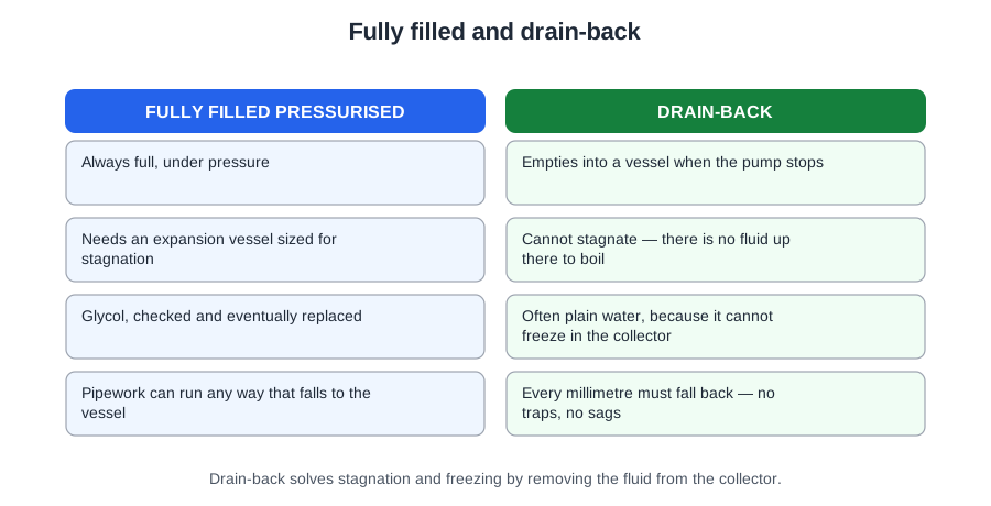
A drain-back system takes the opposite approach: when the pump stops, the fluid falls out of the collectors under gravity into a drain-back vessel. Because nothing is left up there, it needs no antifreeze and no expansion vessel, and it is inherently protected against both freezing and stagnation. An empty collector cannot freeze and cannot cook its fluid. That one behaviour is the whole design.
Tidal volume
The tidal volume is the internal volume of the collectors plus all primary pipework above the drain-back vessel — everything that empties on a stop and refills on a start.
It matters twice. It sizes the vessel, which manufacturers commonly specify at around double the tidal volume so it can neither be overfilled nor run dry. And it sets the lift and priming duty the pump has to overcome on every single start.
The layout rule
The pipework must fall continuously back towards the vessel, with no dips or traps. Any sag holds fluid that cannot drain — and that trapped fluid is exactly what freezes. On a drain-back system a continuous fall is not a preference to be traded against a tidy route; it is the thing that makes the principle work.
What it costs
Higher pump duty, because the pump refills the tidal volume against the full static lift on every start, and a layout constraint that not every property will allow. Those are the two prices paid for losing the glycol and the stagnation problem.
The primary circuit
Design flow rate
Solar primary flow rate is quoted per square metre of collector, and there are three figures to know:
Multiply by the collector area. A 7 m² array at the high rate needs 7 × 0.7 = 4.9 L/min; a 6 m² array at the low rate needs 6 × 0.5 = 3.0 L/min. Read which end of the band the design asks for before you multiply — the three figures differ by 40% across the band, which is a large difference in what the pump has to do.
Getting it wrong in either direction has a cost. Too fast gives a small temperature rise across the collector, poor stratification in the store, and pump energy spent for nothing. Too slow lets the collector run hotter, so its losses climb, its efficiency falls, and stagnation becomes more likely.
MIS 3001 requires the flow rate to be accurately indicated and recorded — which is why a flow meter is fitted and why the commissioning record carries the figure.
Pipe sizing, two ways
There are two routes to a pipe size and they belong together rather than in competition.
The lookup is what most design work and most assessments expect. The CIBSE Solar Heating Design Guide gives a pipe size against the collector area and the total circuit length — flow and return added together, not one leg. Two worked cases, both on an 18 m circuit:
A small step in area crossing a size boundary is precisely the point: it is a table, not a formula, so read it rather than estimating. And use the whole circuit length — halving it by counting only the flow leg is the commonest error, and it is enough to drop a size and leave the pump unable to reach the design flow.
The velocity check is the cross-check. BS 5918 puts numbers on it: velocities below 1 m/s are desirable, and 2 m/s must in no event be exceeded, because excessive velocity causes noise and erosion. Noise the customer hears; erosion they do not — the fluid scours the inside of the pipe, particularly at bends and fittings, and thins the wall over years.
Treat 1 m/s as the design target and 2 m/s as the limit. Designing to the limit leaves nothing in hand for a partly blocked strainer or a pump left on its top speed.
Run length and resistance
Resistance rises with length and with every fitting, so an undersized or over-long run can put the design flow rate beyond the pump's reach entirely. And less flow means heat is not carried away from the collector, so it runs hotter, efficiency falls and stagnation becomes more likely. Keep primary runs short and direct, minimise fittings, use long-radius bends, and insulate the whole circuit.
The pump station and its safety devices
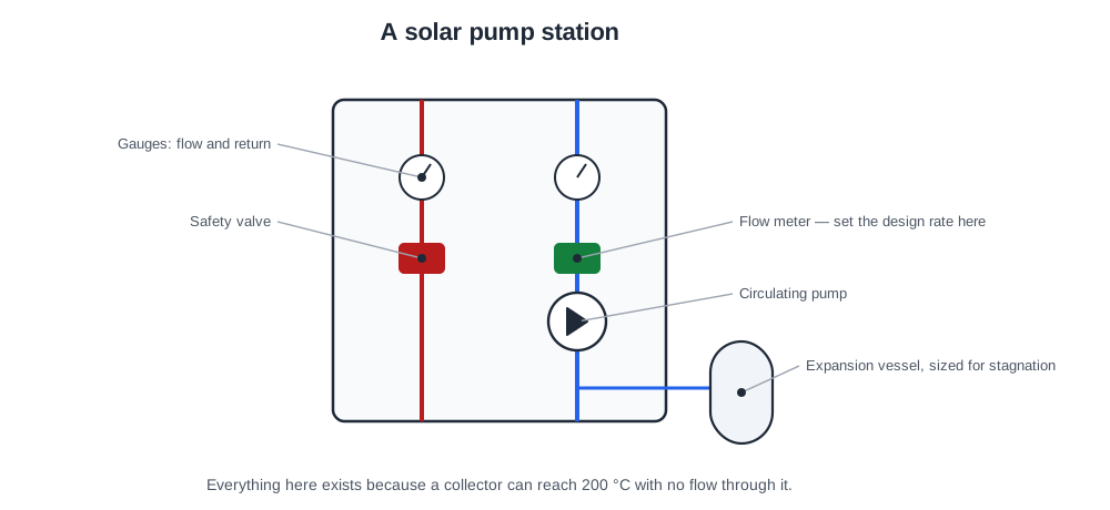
The pump station is the working end of the primary: circulator, isolation, check valve, flow indication, pressure gauge, relief valve and the vessel connection, usually in one assembly near the cylinder. Site it where you can actually reach it — everything you will ever do to this system happens there.
Sizing the pump
Three things: the system flow rate, the solar loop pressure drop, and the pump characteristics. Flow comes from the collector area, resistance from the pipework and fittings, and where they meet on the pump curve is the duty point.
In practice you take two numbers to the manufacturer's data: the flow rate, and the system head in metres. Domestic solar circulators are commonly named for exactly that — a 15(25)/6 is a 15 mm pump with 25 mm unions and a maximum head of 6 m; a 15(25)/4 is the same body with 4 m. So a system head of 4.5 m needs the /6, because the /4 simply cannot reach it. A head of 4.0 m is met by the /4, and specifying the /6 there is oversizing: a bigger pump on a smaller circuit runs further up its curve, draws more electricity and is more likely to be noisy.
Read that maximum head as a ceiling, not a working point. It is the head at zero flow, and the useful duty always sits below it.
The non-return valve
Without one, the circuit will thermosyphon backwards on a clear night — carrying heat out of the store, up to the roof, and radiating it to the sky. A small component preventing a loss that would otherwise run every night of the year.
The expansion vessel pre-charge
Set and check it with the system isolated and the water side depressurised to zero. With pressure on the water side, the system holds the diaphragm against the gas and the gauge tells you nothing at all. Do it before final filling.
Air, and why it matters here
Air in the primary does two things at once: it blocks flow through the sections it occupies, and it makes the pump cavitate rather than circulate. Vents are used during filling and then isolated — because a vent left open at a stagnating collector discharges vapour and then fluid, and the system quietly loses pressure over a summer.
The electrical supply
A dedicated circuit or a clearly identified, correctly rated spur — typically 3 A — with overcurrent protection, RCD protection where required, local isolation, and a label saying what it feeds. A plug and socket is not appropriate for fixed equipment of this kind.
Differential temperature control
A differential temperature controller compares the collector sensor against the store sensor and runs the pump only when the collector is meaningfully hotter than the part of the store it is heating. Below that difference you would spend pump energy to move almost no heat — and could even cool the store.
Two thresholds, not one
The switch-off differential is smaller than the switch-on differential, and that gap is deliberate. Typical values are 6–8 K to switch on and 2–4 K to switch off.
With a single threshold the pump would start, immediately narrow the difference by moving heat, drop below the value and stop — over and over. The gap is the hysteresis, and it is what lets the pump run steadily. Set the two too close and the pump hunts; set the switch-on too high and useful low-level gain either side of midday is thrown away.
Pump speed matters here too. A pump moving heat fast enough to close a narrow band in seconds will cycle whatever the controller is set to, which is why "reduce the pump speed" sits alongside "widen the differential" in the fault-finding list.
Sensor positions decide everything
- The collector sensor goes in the manufacturer's pocket at the flow outlet, reading the fluid actually leaving the collector. On the casing, in the return, or taped to a pipe, it gives the controller a reading that means nothing.
- The store sensor goes low in the cylinder, in the zone the solar coil heats. Fitted high, it reads water the boiler has already heated, sees no useful difference, and the pump never runs at all.
That second one is worth dwelling on, because it produces a system that appears dead while every component tests good. If a system has never performed since installation, check the sensor position before anything else.
What else the controller holds
System type, clock, maximum cylinder temperature, frost protection. All of it is set at commissioning and all of it goes on the controller settings record — because settings drift, customers adjust them, and controls reset after a power failure. Without that record, the next engineer is guessing at what the values ought to be.
Cylinders, coils and dedicated solar volume
The store is where the whole system either works or does not.
The sizing rules
- Dedicated solar volume: 25 litres per net m² of collector area.
- Coil area: at least 10% of the collector aperture area, and around 0.2–0.25 m² per m² of collector.
Coil positions
Solar coil low, auxiliary coil above it. The reason is worth stating rather than memorising: the solar coil low in the store meets the coldest water in the cylinder, which gives the largest temperature difference for heat transfer and returns the coolest possible fluid to the collector. A cooler collector loses less heat, so its efficiency stays high. The whole arrangement follows from that one fact.
Stratification
Stratification is the natural layering of hot water above cold, because hot water is less dense. It lets the top of the cylinder be usable while the bottom stays cold and available to the collector. Draw hot from the top, feed cold in at the bottom through a diffuser, and it survives; stir the store and the solar coil meets lukewarm water instead of cold, transfer falls, the collector returns hotter fluid and its efficiency falls too.
Reusing an existing cylinder
Often asked, occasionally possible. What usually rules it out is the coil rather than the volume — an existing single-coil cylinder has nowhere to put the solar circuit, and a twin-coil intended for a boiler and an immersion rarely has the coil area low down that solar needs.
Jointing
Joints on the solar primary are made with hemp and a high-temperature jointing compound. Not PTFE tape, which is not dependable at solar primary temperatures, and not soft solder, which cannot be relied on at stagnation.
Working with the existing heat source
Solar pre-heats. The auxiliary source guarantees. Neither can do the other's job, and the design has to respect that.
The pasteurisation duty
The auxiliary source must be able to raise the whole stored volume to at least 60 °C. Solar cannot be relied on to do it — there will be weeks when it does not get close — so the backup carries the legionella duty regardless of how well the array performs.
Instantaneous heaters
An instantaneous heater — a combi, or a multipoint — expects a mains-cold feed of roughly 10–20 °C, and many will not modulate correctly on water already at 40 °C. Some shut down entirely. Always check manufacturer approval before connecting one to a solar pre-heat supply.
Where the appliance cannot take it, the clean solutions are a dedicated twin-coil cylinder, or an intermediate blending valve limiting the temperature presented to the appliance.
Timing
Set the auxiliary heat for late afternoon or evening. Heat the store in the morning and you present the collector with a hot cylinder all day, so it collects little and runs hot doing it. Let the sun go first. Getting this backwards is the commonest reason a technically sound installation underperforms — and nothing on it is broken.
What comes next
Module 3 is the regulatory ground: which Parts of the Building Regulations apply and which do not, MIS 3001 and the MCS documents, permitted development and its exceptions, the Water Regulations and legionella, working at height, and safe electrical isolation.
📝 10-Question Mock Test
Click an option to see whether you got it right. Explanations appear instantly — no submitting at the end.
The collector is left empty when the pump stops, so there is nothing up there to freeze and nothing to expand. It is inherently protected against both freezing and stagnation, which is the whole point of the design.
Everything that empties on a stop and refills on a start. It matters twice: it sizes the vessel, commonly at around double that volume, and it sets the lift and priming duty the pump overcomes on every start.
The high end is 0.7 L/min per m², so 7 × 0.7 = 4.9 L/min. Read which end of the band the design asks for before multiplying — 0.5, 0.6 and 0.7 differ by 40% across the band.
The total circuit. Counting only one leg halves the length, and that is enough to drop a pipe size and leave the pump unable to reach the design flow rate. It is the commonest slip on the lookup.
Two figures, easily confused. Treat 1 m/s as the design target and 2 m/s as the hard limit. Excessive velocity causes noise, which the customer hears, and erosion, which they do not.
The number after the slash is the maximum head in metres. A /4 tops out at 4 m and cannot reach a 4.5 m system head; the /6 can. Read it as a ceiling at zero flow, though — the useful duty always sits below it.
It is the one place on a solar circuit where you insulate less rather than more. Fluid coming straight off a collector at 180 °C would destroy the diaphragm; the bare leg takes the edge off it.
Typical settings are 6–8 K on and 2–4 K off. The gap lets the pump run steadily instead of hunting around a single value. Set the two too close and you get clocking; set switch-on too high and useful gain is thrown away.
A store sensor fitted high reads water the boiler has already heated, so the controller sees no useful difference and the pump never runs. Every component tests good, which is exactly what makes it hard — and why sensor position is the first check on a system that has never worked.
One fact, several consequences. The largest temperature difference gives the best transfer, and the coolest return keeps collector efficiency up. Everything else in the cylinder layout — sensor position, draw-off, cold feed — follows from it.
Almost everything in this module follows from one idea: the collector wants the coldest water in the store. Solar coil low, sensor low with it, stratification preserved, auxiliary heat timed for the evening — they are four expressions of the same fact.
And the fault that catches most people is not a component at all. A store sensor fitted high gives a system that has never worked and in which nothing tests faulty. Check the position before you check anything else.