This is the module where underfloor stops being a nice idea and becomes a number. Everything up to here — the construction, the covering, the manifold — exists to deliver a particular watts-per-square-metre figure to a particular room. This article is how you find that figure, and how you find out honestly whether the floor can produce it.
It covers Module 5 of the PlumbMate underfloor heating course: the heat loss inputs, watts per square metre, the surface temperature limits and the emission formula behind them, pipe layouts and centres, pipe quantity, flow rates, and the performance chart check that decides whether the design works. There is a 10-question mock test at the end.
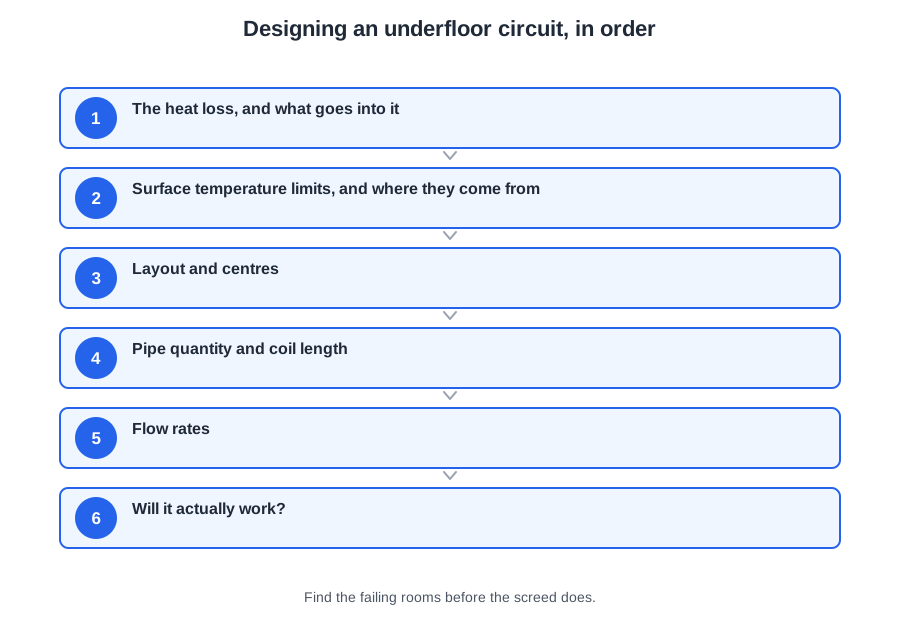
The heat loss, and what goes into it
The inputs are the room dimensions, the building fabric, the desired room temperatures, the outside design temperature, the air change rates and the floor losses. Boiler efficiency is not an input — the heat loss belongs to the building.
The Part L1 U-values worth carrying:
- Floors — 0.25 W/m²K
- Walls — 0.35 W/m²K
- Pitched roof — 0.20 W/m²K, or 0.16 with an attic above
- Windows — 2.00 W/m²K wood, 2.20 metal
Then comes the step that is specific to underfloor. A radiator design stops at a number of watts. An underfloor design divides that by the heated floor area to get watts per square metre, because that is the unit the floor is judged in.
Surface temperature limits, and where they come from
Three design conditions, each pairing a surface temperature with a room temperature and an output:
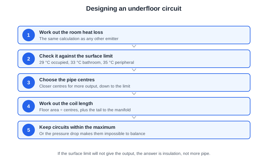
- Occupied area — 29 °C surface, 20 °C room, 100 W/m²
- Bathroom — 33 °C surface, 22 °C room, 121 W/m²
- Peripheral area — 35 °C surface, 20 °C room, 175 W/m²
Covering limits can pull those down — vinyl and laminate cap at 27 °C regardless.
Those are not three facts to memorise separately. They come out of one formula:
q = 8.92 × (AFST − ART)1.1, in W/m²
where AFST is the average floor surface temperature and ART is the average room temperature. Put 29 over 20 into it and you get exactly 100 W/m². Put 35 over 20 in and you get 175. The table is the formula, worked at the limits.
The 1.1 exponent is there because a large part of the transfer is radiant, so output is not linear with temperature difference. It is also why the formula is worth knowing rather than just the table: read it backwards and you can answer the more useful question. A room that needs 60 W/m² wants a floor at around 25.5 °C — comfortably inside the cap, with room to spare.
Three things set the surface temperature you actually get: the floor covering, the pipe spacing, and the water temperature.
Layout and centres
Two layouts, and the difference between them is real:
- Series, or meander. The pipe switches back on itself across the room. The water cools progressively along the run, so a meander is started at the coldest side of the room — usually the external wall.
- Spiral, also called snail or bifilar. Flow and return run alongside each other the whole way, so a cooling flow pipe always has a warm return pipe next to it. The result is a far more even floor temperature.
Both come in standard and modified forms; modified concentrates pipe where the loss is greatest.
What actually influences the choice of layout: the surface finish limits, the surface area and coil length, the distance from coil to header, and unequal perimeter energy. What does not influence it: the boiler type, the radiator sizes, or the water temperature.
Pipe sizes are 15, 16, 18 and 20 mm. Centres are 100, 150, 200, 250 and 300 mm. 200 mm is the generally accepted spacing on a screeded floor over floor-grade insulation.
Two refinements. Run the flow round the outside wall first, at 150 mm — closer centres put more output where the wall is losing most. And where several circuits bunch together crossing a hallway on their way elsewhere, insulate the individual pipes through that stretch, or the hall floor will overheat with heat that no room thermostat has any authority over.
Pipe quantity and coil length
The arithmetic is one line:
Pipe length = floor area ÷ spacing in metres
20 m² at 200 mm centres is 20 ÷ 0.2 = 100 m. The mistake to watch for is multiplying instead of dividing: 20 × 0.2 gives 4 m, which should stop anybody in their tracks.
Then add the flow and return legs back to the manifold — taken as 5 m each in the assessment, so +10 m per circuit.
Worked through on the dining room of the module's bungalow, 14 m² at 200 mm centres:
- 14 ÷ 0.2 = 70 m of pipe in the floor
- plus 10 m of tails = 80 m
- Coils come in 50, 75 and 100 m, so that is a 100 m coil
The rounding matters more here than in most calculations, because pipe below ground is laid without joints. There is no making up a shortfall. On a larger scheme the economical method is the manufacturer's tube trimming charts, which fit the circuits to the available coil lengths across the whole job rather than room by room.
Flow rates
One formula:
kW ÷ 4.2 ÷ ΔT × 60 = litres per minute
4.2 is the specific heat capacity of water in kJ/kg·K, and the density is 1 kg per litre, which is what lets kilograms and litres be used interchangeably here.
Two rooms from the bungalow, both at a differential of 8 K:
- Kitchen — 16 m² at 60 W/m² = 0.96 kW → 0.96 ÷ 4.2 ÷ 8 × 60 = 1.71 l/min
- Conservatory — 14 m² at 150 W/m² = 2.1 kW → 2.1 ÷ 4.2 ÷ 8 × 60 = 3.75 l/min
A word about that differential, because it is a genuine inconsistency and it is better to know about it than to be surprised by it. BS EN 1264 Parts 2 and 3 recommend 5 K, and that is the figure to give when a question asks what the standard recommends. Worked examples in industry training material commonly run at 8 K. Both appear in practice. Use the standard's figure when you are asked about the standard, and use the design's figure when you are working a design.
Will it actually work?
The last step is the one that separates a design from a hope. Manufacturers' performance charts take four inputs — water temperature, room temperature, pipe centres and floor covering resistance — and give two outputs: the heat emission in W/m², and the resulting floor surface temperature.
Read those off, room by room, and compare with what each room needs. On the bungalow, at a flow temperature of 40 °C:
- Kitchen and dining — 91.8 W/m²
- Bathroom — 57.0 W/m² (designed at 22 °C: 8.92 × (27.4 − 22)1.1)
- Bedrooms — 58.8 W/m²
- Conservatory — 105.8 W/m²
- Living room — 50.8 W/m²
Against a requirement of 60 W/m² in the general rooms, the living room falls short at 50.8, the bedrooms are marginal at 58.8 and the bathroom at 57.0. Against the conservatory's 150 W/m², 105.8 fails badly.
That is not a failure of the method. It is the method working: it has told you, before anything is buried, exactly which rooms need attention. Four levers, in the order you should reach for them:
- Close the pipe centres — cheap now, impossible later
- Change the covering — if the choice is still open
- Raise the flow temperature, within the 55 °C limit and whatever the floor finish allows
- Add supplementary heat — the honest answer for a conservatory
📝 10-Question Mock Test
Click an option to see whether you got it right. Explanations appear instantly — no submitting at the end.
Floors 0.25, walls 0.35, pitched roof 0.20 (0.16 with an attic above), windows 2.00 wood and 2.20 metal.
35 °C over a 20 °C room gives 175 W/m². Occupied areas are 29 over 20 for 100, and a bathroom 33 over 22 for 121.
AFST is the average floor surface temperature and ART the average room temperature. Put 29 over 20 in and it gives exactly 100 W/m²; 35 over 20 gives 175.
Read it backwards and it becomes useful rather than academic: 60 W/m² needs a floor at only about 25.5 °C, comfortably inside the cap.
In a spiral, a cooling flow pipe always has a warmer return pipe beside it. A meander cools progressively along the run, which is why it is started at the coldest side of the room.
Layout is decided by the floor and the room. Boiler type, radiator sizes and water temperature are not influences on it.
14 ÷ 0.2 = 70 m in the floor, plus 10 m of tails is 80 m. Coils come in 50, 75 and 100 m, so 100 m — and there is no making up a shortfall, because pipe below ground is laid without joints.
20 m² at 200 mm centres is 20 ÷ 0.2 = 100 m. Multiplying instead would give 4 m, which should stop anybody in their tracks.
16 × 60 = 0.96 kW. Then 0.96 ÷ 4.2 ÷ 8 × 60 = 1.71 l/min. The 4.2 is the specific heat capacity of water in kJ/kg·K.
Closer centres are cheap now and impossible once the pipe is buried. Then the covering, then the flow temperature within limits, and supplementary heat last.
The reason to work all seven rooms rather than the worst one is that you cannot tell in advance which rooms will fail. A conservatory with a huge glazed load and a living room with a thick carpet fail for completely different reasons, and both would have looked fine on a whole-house average. Room by room, before the screed, is the only version of this that is worth anything.