A customer rings and says they want “renewables” on the house, and that they want to cut their electricity bill. Before you can price anything, you have to establish which technology they actually mean.
The short answer
Micro-renewables fall into two families — heat and electricity — and the first question on any survey is which one the customer is after.
A customer who wants a lower electricity bill needs solar PV. Solar thermal makes hot water and would only reduce an electricity bill where an immersion heater was doing the water heating.
And for heat pumps, one idea explains everything else: a heat pump does not make heat, it moves heat — so the lift it works across, not the machine, decides the bill.
What each technology produces
| Technology | Output | Energy source |
|---|---|---|
| Solar thermal | Heat, for hot water | Solar radiation |
| Ground source heat pump | Heat | Low-grade heat in the ground |
| Air source heat pump | Heat | Low-grade heat in the air |
| Biomass | Heat | Wood pellets, logs or chips |
| Solar PV | Electricity | Solar radiation |
| Micro-wind | Electricity | Wind |
| Micro-CHP | Heat and electricity | Mains gas |
Solar thermal heats a fluid in a collector and that fluid heats the stored hot water. It produces heat only, and no electricity at all.
Biomass burns biological material — the main domestic fuel is wood pellets, pressed from sawdust and shavings. It is a combustion appliance, so it needs a flue, a hearth and air supply designed to Approved Document J, plus fuel storage with delivery access.
Two duties come with burning a solid fuel that a gas boiler has neither of: the fuel has to be fed in mechanically, normally by an auger from a hopper, and what is left has to be taken out again — burning timber leaves ash, and the customer has to be told at handover that emptying it between services is their job. The flue must be one suitable for solid fuel, not a gas flue. It is called carbon-neutral because growing timber absorbs the carbon dioxide that burning it releases.
Solar PV converts solar radiation directly into d.c. electricity in silicon cells. On a roof it can look almost identical to solar thermal, but the two are entirely different technologies with different components, regulations and economics.
Micro-wind siting decides whether one is worth fitting at all: average wind speed (about 5 m/s is the practical minimum), obstructions and the turbulence they cause, mounting height, and noise, vibration and flicker. Soil type, the water table and roof orientation belong to other technologies.
Micro-CHP straddles both families. Domestic units are gas fired and use a Stirling engine. They are heat led: roughly 80 per cent heat and about 15 per cent electricity, typically 1 to 1.5 kW, and the unit only generates when there is a call for heat.
Two mistakes cost money. Selling solar thermal to somebody who wanted PV, or the reverse. And quoting for a technology the property cannot take: solar thermal needs stored hot water, a heat pump needs low flow temperatures and a well insulated building, biomass needs somewhere dry for several cubic metres of fuel, and a turbine needs wind most built-up sites do not have. Ask what the customer wants to reduce — the gas bill, the electricity bill or the carbon — and the technology usually chooses itself.
The refrigeration cycle
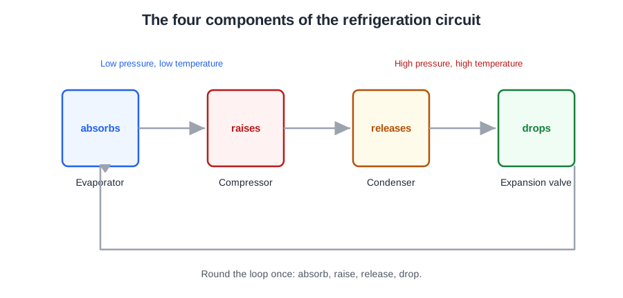
You are standing in a garden at 2 °C next to a box heating the house. Heat exists in anything above absolute zero, which is 0 K, or −273 °C. Air at −5 °C still holds an enormous amount of heat energy; it is simply at too low a temperature to be useful.
Heat only ever flows from a warmer place to a cooler one, so to collect that heat the machine needs something colder than the outside air. That something is the refrigerant — a fluid chosen because its boiling point changes with pressure. Lower the pressure and it boils colder. That single fact is what makes the whole machine work.
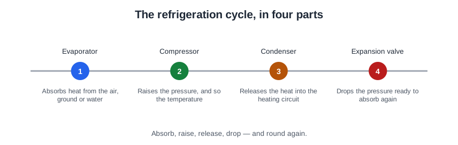
- The evaporator absorbs low-grade heat from the source. The refrigerant arrives cold and at low pressure, the air or ground loop is warmer than it is, so the refrigerant boils and turns to vapour.
- The compressor raises the pressure of that vapour, and with it the temperature. This is the only part of the machine that needs a power supply.
- The condenser releases the heat. The hot high-pressure vapour is now hotter than the heating water, so it gives up its heat and condenses back to a liquid.
- The expansion valve drops the pressure again. The boiling point falls back below the source temperature, and the cycle starts over.
The high-pressure side runs from the compressor discharge into the condenser, and the refrigerant is a high-pressure liquid leaving the condenser, before the expansion valve.
The cycle uses a change of state rather than simply warming a fluid, because latent heat carries far more energy per kilogram than a temperature change does. That is why steam scalds so badly, and why a small mass of refrigerant can carry a domestic heat load.
A unit delivering 9 kW while drawing 2.5 kW looks as though it breaks the rule that energy cannot be created. It does not: the other 6.5 kW was collected outside and moved indoors. For the same reason, calling a heat pump 400 per cent efficient is misleading — efficiency describes converting one form of energy into another, and no conversion can exceed 100 per cent. A heat pump is a transport ratio, not a conversion efficiency.
The refrigerant circuit is F-Gas work. Two hazards matter even when you are only working nearby. Never apply a flame to a circuit that has not been recovered: refrigerant decomposes into toxic and corrosive products, far more dangerous than the refrigerant itself. And a leak in a small plant room is dangerous because refrigerant is heavier than air: it pools at low level and can displace oxygen with very little warning.
CoP and lift
CoP is the rate of heat delivered divided by the power input. A unit giving 9 kW for 2.25 kW has a CoP of 4.0; for ground source the value is normally between 3 and 4.
CoP is a snapshot at one set of temperatures. The figure that matters over a year is the seasonal coefficient of performance (SCoP): annual heat delivered divided by annual electricity consumed. Because a season takes in cold spells, part-load running and defrost cycles that a bench test at one mild condition leaves out, the seasonal figure is always the lower of the two.
Lift is the temperature difference between the source and the temperature the machine must deliver at, and it is the whole story: the smaller the lift, the more efficient the system, because the lift is provided by the compressor and the compressor is the part that costs money to run.
That explains why ground beats air in cold weather. On a −3 °C morning with both units delivering 45 °C, the ground source unit collects from a loop at 8 to 12 °C all winter while the air source unit collects from air at −3 — roughly 13 K less lift for the same output.
| Source | Flow temperature | Lift | Effect |
|---|---|---|---|
| 2 °C | 50 °C | 48 K | Baseline |
| 2 °C | 40 °C | 38 K | About 20–25 per cent better |
| −3 °C air | 45 °C | 48 K | Worst case for an air source unit |
| 10 °C ground | 45 °C | 35 K | Ground source on the same morning |
As a rule of thumb, efficiency changes by roughly 2 to 2.5 per cent for every degree of lift, so 10 °C of reduced flow temperature is worth about 20 to 25 per cent.
The most common mistake on a retrofit: a boiler is swapped for a heat pump and the existing radiators are left as they are. Those radiators were sized for 70 to 80 °C flow. At 45 they cannot deliver the room loads, the house is cold, and the only lever left is to raise the flow temperature. The lift widens, the CoP falls, and the customer complains about the running cost. Nothing has failed; the emitters were never sized for the machine.
So the single change that most improves the seasonal efficiency of an existing installation is to reduce the flow temperature — larger emitters, underfloor heating, or better fabric so the loads fall. Raising the flow temperature, fitting a bigger heat pump or adding a buffer do not touch the lift, and the first makes it worse.
Air source: frost and defrost
An ASHP is a packaged outdoor unit: a fan, a heat exchanger acting as the evaporator, a compressor, an expansion valve, and a second heat exchanger passing heat to the system water. No ground loop, no solar collector and no flue. Air-to-water units heat water; air-to-air units heat air only and cannot heat water.
Falling outdoor temperature affects an ASHP in two ways at once: there is less heat in the air, and the lift widens. Both move the wrong way at precisely the moment the building needs the most heat — which is why it is not economic to size an air source unit for the very coldest conditions.
The evaporator coil runs colder than the outside air. When the air is damp, moisture condenses on the fins and freezes. Frost is worst in damp weather around 0 to 6 °C — not in the very coldest weather, because very cold air is usually dry.
The cure is the defrost cycle, achieved by a temporary reversal of the heat pump. The component that makes it possible is the reversing valve, which swaps the roles of the two heat exchangers so the outdoor coil briefly acts as the condenser.
That heat comes from the system water — so while a defrost is running the unit is taking heat out of the building rather than putting it in, and space heating is interrupted. The radiators cool, the house gives up a little ground each time, and the electricity is being paid for throughout.
If defrosts are far more frequent than expected, look at the air side: inadequate clearances so the unit recirculates its own cold discharge; debris restricting airflow; meltwater failing to drain and refreezing. Inhibitor concentration is a water-side matter and has no bearing on frost forming on an outdoor coil.
Two lockouts come up again and again. A repeated LOW pressure lockout in cold weather means the evaporator cannot absorb enough heat — a source-side problem: icing, debris, or clearance. It is not the radiators and it is not the compressor. A tripped high pressure switch is a protective device that opened for a reason; resetting it and leaving is not a repair.
And persistent bubbling in the sight glass at steady state is not normal: clear liquid is normal, and continuous bubbles point to an undercharge or non-condensable gases — a diagnosis to report, not to fix.
Ground collectors
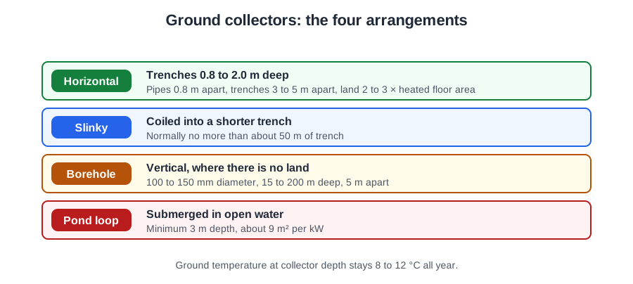
There are four common types of ground loop in the UK: vertical, pond, slinky and horizontal, and the site usually picks one for you. All four are closed loop: a sealed circuit of plastic pipe, normally HDPE or PE-X of 25 to 40 mm, filled with water and antifreeze — brine — circulated by its own pump.
- Horizontal. Trenches at 0.8 to 2.0 m deep. Cheap, but it needs a large boulder-free area that cannot be built over, and it carries a risk of frost heave if undersized.
- Vertical (borehole). Grouted boreholes of 100 to 150 mm diameter, 15 to 200 m deep, with a minimum spacing of 5 m so adjacent holes do not draw on the same heat. Suits restricted sites, can be built over, and is the most efficient option.
- Slinky. A continuous coil, overlapped flat in a wide trench or upright in a narrow one. It fits more pipe into each metre of trench.
- Pond. Coils or plates anchored in water, needing a minimum depth of 3 m and roughly 9 m² of water surface per kW.
Why a borehole is the most efficient is depth. Near the surface the ground follows the air a few weeks behind, so a shallow trench is at its coldest in the very weeks the building wants the most heat. Below roughly 4 m the ground stays within about ±2 K of the annual average air temperature and a borehole barely feels the season. A steadier source means a narrower lift in midwinter.
A slinky is often proposed to squeeze a collector onto a small plot, and that is the wrong reason. The coils still have to be spaced so they do not draw on the same ground, so the area is barely reduced. What a slinky saves is trench length — and trench length is where the excavation cost sits. Where there is no land, the answer is boreholes.
And an undersized horizontal array draws heat out of the soil faster than the ground replaces it: the soil freezes, frozen ground expands, and the expansion lifts the pipe and the surface. The cause is the design, not the weather.
An open loop system abstracts water from a well, borehole or watercourse and returns or discharges it. Because it takes water from the environment, it typically needs an abstraction licence — which a closed loop does not.
Be careful with the claims. Ground source has real advantages — no combustion on site, no fuel storage, long life, low maintenance. But it is not true that a heat pump has no moving parts (compressor, circulators, fan or brine pump), not true that it needs no ground works, and certainly not true that it fits any size of garden.
Sizing a ground collector
The heat a heat pump delivers is the heat it collected plus the electrical energy the compressor used, so the ground never has to supply the full output. An array is sized on output minus input.
| Step | Sum | Result |
|---|---|---|
| Electrical input | 9 kW ÷ CoP 4.0 | 2.25 kW |
| Heat from the ground | 9 − 2.25 | 6.75 kW |
| Collector length | 6,750 W ÷ 20 W/m | 338 m |
| Ground area at 1 m centres | 338 m × 1 m | 338 m² |
Size it on the full 9 kW and you have paid for 450 m of pipe you did not need.
Two things set the specific heat extraction rate: the soil or rock type, including how wet it is, and the annual run hours the design assumes. Wet clay gives up far more than dry sand, and an array worked hard all year gives up less per metre.
For a sanity check: about 10 to 40 W per m² for a horizontal collector, and 20 to 55 W per metre of borehole. A figure well outside those bands is one to question before the digger arrives.
Those assumed run hours have a name: FLEQ, the full load equivalent run hours assumed annually — the hours the system would run at full output to deliver the year's heat.
Horizontal pipe is laid at 1 m centres, which makes the area sum simple: 340 m of pipe needs 340 m² of ground. Then compare with the ground actually available. If the design needs 420 m² and the plot has 380 m², the check fails and the design must change before work begins. Closer centres do not create ground; they only make each metre of pipe work harder, and 380 being "close enough" to 420 is not a calculation.
You would not lay 338 m as one run. The maximum loop length is about 100 m for 25 mm pipe, so the array is divided into roughly equal circuits back to a manifold — here, four circuits of about 85 m. Equal lengths balance naturally, each circuit can be isolated and purged, and the pump duty stays sensible.
Monovalent, bivalent and system volume
A monovalent system uses one kind of heat source, covering 100 per cent of the demand at all times. A bivalent system uses two or more generators of different kinds, and the outdoor temperature at which the second has to start contributing is the bivalence point.
The distinction is the kind of source, not the number of machines. Two heat pumps in cascade are still monovalent, because both collect from the same kind of source.
Bivalent systems run in one of two ways: parallel operation, where both run together once the load exceeds what the heat pump can do; and alternate operation, where the heat pump drops out entirely — used where the emitters need temperatures the heat pump cannot reach. Output and CoP both fall as the weather gets colder, so it is rarely economic to size a heat pump for the coldest few days.
A heat pump does not produce instant heat and does not like starting and stopping. Short cycling wastes energy and shortens the compressor's life, and what prevents it is enough water in the system to absorb the output when the emitters do not want it.
This matters far more with a fixed-speed unit than an inverter-driven one. An inverter can throttle its compressor back to match the load; a fixed-speed unit runs at full output or not at all, so whenever demand is below its output the surplus has to go somewhere.
The answer is a buffer vessel: an insulated vessel of heating water the pump can dump surplus heat into. It is why an air source unit feeding underfloor heating so often needs one too — zone valves closing can leave the machine with almost nothing to heat, and the buffer also provides the volume to run a defrost without robbing the house.
How much volume is enough is a manufacturer's figure, usually litres per kilowatt of output. If the emitters and pipework already hold it, a buffer may not be needed at all. If the system is small, heavily zoned, or fitted with TRVs that can close most of it off, the volume on paper disappears the moment the house is up to temperature.
Note what a buffer is not. It is not a hot water cylinder — it holds heating water. And it does not improve efficiency: it protects the machine from cycling. The lever that improves seasonal efficiency is still the flow temperature.
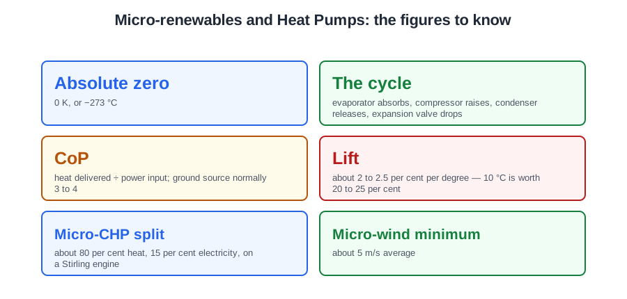
🔢 The numbers worth memorising
- Absolute zero
- 0 K, or −273 °C
- The cycle
- evaporator absorbs, compressor raises, condenser releases, expansion valve drops
- CoP
- heat delivered ÷ power input; ground source normally 3 to 4
- Lift
- about 2 to 2.5 per cent per degree — 10 °C is worth 20 to 25 per cent
- Micro-CHP split
- about 80 per cent heat, 15 per cent electricity, on a Stirling engine
- Micro-wind minimum
- about 5 m/s average
- Frost worst at
- 0 to 6 °C in damp weather
- Defrost component
- the reversing valve
- Ground loop pipe
- HDPE or PE-X, 25 to 40 mm, filled with brine
- Horizontal trench
- 0.8 to 2.0 m deep, pipe at 1 m centres
- Borehole
- 100–150 mm diameter, 15–200 m deep, 5 m apart
- Pond loop
- minimum 3 m depth, about 9 m² per kW
- Below 4 m
- ground stays within about ±2 K of the annual average
- Extraction rates
- 10–40 W/m² horizontal, 20–55 W/m of borehole
- Maximum loop
- about 100 m for 25 mm pipe
- 9 kW at CoP 4
- 6.75 kW from the ground, 338 m at 20 W/m
⚠️ Where people go wrong
- Selling solar thermal to a customer who wanted PV, or the reverse.
- Calling a heat pump 400 per cent efficient. It is a transport ratio, not a conversion.
- Forgetting a biomass appliance needs a solid fuel flue, mechanical feed and ash removal.
- Quoting CoP where SCoP is the honest figure. The seasonal number is always lower.
- Leaving existing radiators on a heat pump retrofit, then raising the flow temperature to compensate.
- Expecting frost in the very coldest weather. Damp air at 0 to 6 °C is worse.
- Blaming inhibitor for icing on an outdoor coil.
- Resetting a tripped high pressure switch without asking why it rose.
- Applying a flame to a refrigerant circuit that has not been recovered.
- Proposing a slinky to save area. It saves trench length.
- Undersizing a horizontal array. The ground freezes and heaves.
- Sizing a collector on the full output instead of output minus input.
- Tightening the pipe centres to fit an array onto a plot that is too small.
- Calling two cascaded heat pumps a bivalent system.
- Treating a buffer as a hot water cylinder, or as an efficiency measure.
📝 10-Question Self-Test
Straight from the Level 3 course question bank. Click an option to see whether you got it right — the explanation appears instantly, and there is nothing to submit.
Electricity and heat, together, from one fuel. A micro-CHP unit runs an engine or a similar prime mover to generate electricity and captures the heat that would otherwise go up the flue, using it for the heating and hot water. Because the electricity is a by-product of running for heat, it only pays in a dwelling with a high space heating demand. It produces no hydrogen and no cooling.
Domestic micro-CHP units use a Stirling engine (the paper spells it Sterling), an external combustion engine driven by the burner's heat.
An evacuated tube collector seals the absorber inside a glass tube with the air pumped out. The vacuum removes conduction and convection losses almost entirely, so the collector holds its output in cold, windy weather and reaches higher temperatures than the other main type, the flat plate. The textbook describes a coated, double walled tube; the design guides describe a metal absorber, direct flow or heat pipe, sealed in a single tube. Finned, ribbed and ventilated tubes are not solar collectors at all.
A heat pump does not make heat, it moves it, on the same refrigeration cycle as a fridge: the evaporator absorbs, the compressor raises pressure and temperature, the condenser releases, and the expansion valve drops the pressure again. Dropping the pressure lowers the refrigerant’s boiling point below the ground temperature, which is the only way heat will flow into it. Nothing burns, so combustion is not involved.
An air source unit is a packaged outdoor box holding a fan, a heat exchanger acting as the evaporator, a compressor, an expansion valve, and a second heat exchanger that passes the heat into the system water. A ground loop collector belongs to ground source and a solar panel to solar thermal. A flue gas condenser is boiler equipment: a heat pump burns nothing, so it has no flue.
The main domestic biomass fuel is wood pellets, pressed from sawdust and shavings, with logs and wood chips as the alternatives. Biomass is called carbon neutral because growing timber absorbs the carbon dioxide that burning it releases. Kerosene and LPG are fossil fuels and smokeless ovoids are a coal product, so none of them is biological material.
Domestic micro-CHP units are gas fired and use a Stirling engine, an external combustion engine driven by gas expanding and contracting as it is alternately heated and cooled. The unit is heat led, generating only while the appliance is heating the house, typically 1 kW to 1.5 kW of electricity. Diesel, two stroke petrol and Wankel engines are internal combustion and are not used in these appliances.
Annual run hours drive how hard the ground is worked, and so how big the array must be.
Wet clay gives up far more than dry sand, and a hard-worked array gives up less per metre.
Delivered heat = ground heat + compressor work, which is why the array is sized on output minus input.
Going further: the lessons behind this article
This article is the public answer. Unit 335 of the Level 3 course takes the same ground to the depth the exam and the synoptic assignment ask for, in 7 lessons:
- Micro-renewable technologies: what each one produces
- Heat pumps: how the refrigeration cycle moves heat
- CoP and lift: why flow temperature decides efficiency
- Air source heat pumps: frost, defrost and fault finding
- Ground source heat pumps: the four collector types
- Sizing a ground collector: extraction rates and area
- Monovalent, bivalent systems, buffers and system volume
- Environmental technology systems: the Unit 335 guide — every article on this unit in one place
- All PlumbMate articles — Level 1, 2 and 3
- The Level 3 course — the whole 8202-35 Diploma