A developer hands you the drawings for a pair of three-bedroom houses and asks for a price on the sanitation. Before you draw a single pipe you have to answer three questions.
The short answer
How many appliances, of what kind, and how hard will they be worked. Almost every figure later in the design — branch sizes, stack size, room layouts — comes out of those answers.
And one factor governs the shape of the whole system: how far the appliances are from the discharge stack. Grouped tightly round it, you get the simplest arrangement with no separate ventilating pipes. Strung out along a wall, you are into ventilated branches, an air admittance valve or a second stack.
Starting from the people
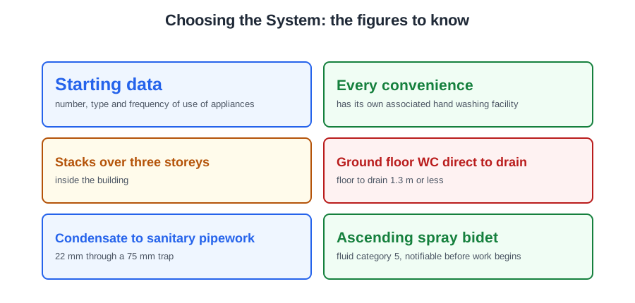
Sanitary appliances receive and discharge soil and wastewater safely. Soil is the discharge from WCs and urinals; waste is the discharge from basins, baths, showers, sinks and appliances such as washing machines. Surface water from a paved area is not sanitation, and neither is boiler condensate — though condensate may be connected to sanitary pipework in a minimum 22 mm pipe through a 75 mm condensate trap.
Occupancy is the first figure, and from it comes the number, type and frequency of use of the appliances. That trio does more than fix the drainage: in a single occupancy dwelling it also decides which type of hot water system to select, because how many hot outlets there are and how often they run together is exactly what sets the hot water demand.
Approved Document G sets the floor: any dwelling should have at least one sanitary convenience and an associated hand washing facility, and Approved Document M requires that convenience to be on the principal or entrance storey. Where additional conveniences are provided, each one needs its own associated hand washing facility — so when a cloakroom is designed, the appliance that has to sit close to the WC is a wash basin.
That basin may go in the room containing the convenience, or in an adjacent room that is the sole means of access to it, provided that room is not used for preparing food. (One small handover detail from the same document: where hot and cold taps are fitted to a sanitary appliance, the hot tap goes on the left.)
Above that minimum, the standard for sanitary accommodation is BS 6465: Part 1 for the scale of provision, Part 2 for space, Part 3 for selection, installation and maintenance.
The documents, and the people
Sanitary pipework is controlled work under Part H in England and Wales, Part N in Northern Ireland. Approved Document H divides into H1 foul water drainage, H2 wastewater treatment, H3 rainwater drainage, H4 building over sewers, H5 separate systems and H6 solid waste storage.
No one document answers everything. A design draws on Approved Document H for branch sizes, lengths, gradients and stack diameters; G for provision, F for ventilation of sanitary accommodation, B for fire stopping and M for access; BS EN 12056 as the code of practice; BS 6465 for provision and space; BS 8000-13 for workmanship; and manufacturers' instructions for anything carrying a performance figure.
Then there are the people. On a large housing site the architect is the one to ask where the sanitary appliances go, because it is the architect's drawings that fix their positions. A finished floor level is on the detailed plans — not the block plan, the programme of works or the schedule of rates. On an existing property the customer is a source in their own right: they can tell you what has blocked and what has smelled. And before any servicing or remedial work on an appliance, the customer's agreement is the first thing to obtain.
Awkward layouts
Building features weigh as heavily as distances: a solid floor that cannot be chased, the direction of the joists, a bay window where the stack wants to run, a party wall, a listed elevation. And one hard rule for taller work — in buildings over three storeys, discharge stacks should be located inside the building.
A ground floor WC may only discharge directly to a drain where the depth from floor to drain is 1.3 m or less. Where the drain is too high, or the appliance sits below it, gravity is not available and a pumped appliance is the answer — a WC macerator, or a wastewater lifter covered by BS EN 12056-4.
Both are sized by the manufacturer, and the pipe run is part of that sizing. Connect a lifter to a discharge pipe longer or higher than the unit is rated for and the motor keeps running after the water has drained, because the extra friction is more than the pump can clear quickly.
Two other faults are worth knowing:
- A macerator that keeps starting up on and off after the appliance has finished discharging has a defective non return valve, letting the pumped water fall back into the chamber.
- A unit that runs for a long time after each flush is usually blocked.
Fault finding on any of these starts the same way: talk to the customer, then run the unit and check that it operates as the manufacturer describes. Stripping it down or ordering a pump before you have seen the fault is guesswork.
Appliances that carry a water regulations duty
A bidet with an ascending spray or a flexible hose is notifiable work under Regulation 5. The water undertaker must be given notice, and consent, before the work begins. An ascending spray bidet is one where the spray enters from the base of the appliance, below the rim, so the spray head can be submerged in dirty water — which is why it is a fluid category 5 backflow risk.
A pressure flushing valve on a WC or urinal is another: it needs a permanently vented type DC pipe interrupter at least 300 mm above the spill-over level.
Two smaller details come up again and again. A servicing valve must be fitted upstream of, and as close as practicable to, every float-operated valve — which includes the inlet valve of a close-coupled WC cistern, so it goes on the cold feed, not a drain-off, a pressure reducing valve or a strainer. And on a traditional high level WC suite the cistern is joined to the pan by a 32 mm flush pipe; a low level suite uses the larger 38 mm size.
Activity space
A cloakroom measuring 900 × 1500 mm. The WC and basin both fit on paper. On site the door fouls the basin and nobody can stand in front of the pan. The appliances fitted; the space to use them did not.
BS 6465-2 separates the room into three areas:
- Appliance space — the area taken by the appliance and its closely related pipework.
- Activity space — the area needed, in addition, for the user to carry out the activity, and for cleaning and routine maintenance.
- Circulation space — the area free of obstruction needed to reach an appliance without interfering with someone using another.
Where do the activity space figures come from? Not from flow rates, not from stack diameters, not from dead leg lengths. They are worked out from the dimensions of the human body — the size of a person and the way they move while using the appliance. The recommended activity space is the overall downward projection of the user areas at various heights.
| Appliance | Activity space |
|---|---|
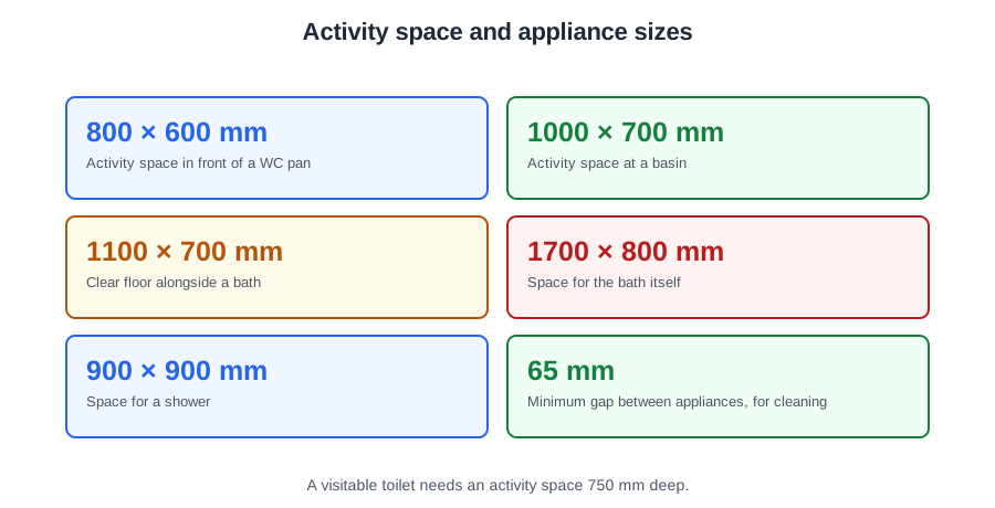
| Wash basin (domestic) | 1000 mm wide × 700 mm deep |
| Hand rinse basin | 800 × 600 mm |
| WC (domestic) | 800 × 600 mm |
| Bidet | 800 × 600 mm |
| Bath | 1100 × 700 mm clear floor alongside |
The bath figure is worth a sentence. The 1100 × 700 mm space alongside allows for getting in and out, for drying, and for an adult standing beside the bath bathing a child. It does not have to run the whole length and can sit at any point along it, preferably the tap end.
Nominal appliance sizes, for when the appliance is not yet chosen: bath 1700 × 800, shower 900 × 900, domestic wash basin 600 × 500, close-coupled WC suite 500 × 700 mm.
Activity spaces may overlap where simultaneous use of the two appliances is unlikely — the basin and the WC in a domestic bathroom, for instance. Where simultaneous use is likely, they must not.
Two allowances often get forgotten. Where surfaces are not continuous, leave a minimum gap of 65 mm between appliances so they can be cleaned between. And BS 6465-2 asks for maintenance and cleaning space: working room around rodding points and valves, including room to take a fitting apart and put it back. For a WC pan, keep a minimum clearance of 200 mm between the side of the pan and any wall if the activity space is displaced from centre. In a visitable toilet the depth of the activity space increases from 600 mm to 750 mm.
Space requirements for disabled access are more generous and are set elsewhere: Approved Document M with BS 8300 for the detail.
Combined, separate and partially separate
- Combined — foul and surface water in the same pipe. Any rainwater pipe discharging into a combined system must do so through a trap, so foul air cannot escape at the gutter.
- Separate — the rainwater downpipe runs to its own surface water drain, the soil stack to a foul drain. They leave the site separately and never join.
- Partially separate — most surface water goes to the surface water drain, but one or two connections are allowed into the foul drain.
Requirement H5 is why new work usually ends up separate: it requires the rainwater system to be separate from the foul one where the drainage connects to a public sewer system that already provides separate sewers, or where separate sewers are under construction. The purpose is to minimise the volume of rainwater entering the public foul sewer, which can overload it and cause flooding.
Approved Document H3 sets an order of preference for surface water: a soakaway or other infiltration system where practicable; then a watercourse; then a sewer, only where the other outlets are not practicable.
Infiltration is not always possible. An infiltration device should not be built within 5 m of a building or a road, in unstable ground, where the water table reaches the bottom of the device at any time of year, or where contamination could pollute groundwater. Soakaways are designed to a return period of once in ten years, and for a small soakaway serving 25 m² or less a design rainfall of 10 mm in 5 minutes may be assumed. Where a site cannot pass its runoff on at the rate it arrives, the flow is attenuated.
The survey comes first: establish whether the property is combined, separate or partially separate before you assume where a new downpipe can go. And if an extension is added, the gutter size, the number of outlets and the downpipe may all need recalculating.
Two above ground rules follow directly from the drain below. Branch pipes should not discharge into open hoppers, and a branch discharging to a gully should terminate between the grating and the top of the water seal.
Fire stopping, access and notification
A 110 mm plastic soil stack rises through the concrete floor between two flats. The hole has been packed with a tube of frame sealant. It looks tidy. In a fire it would be a chimney between two homes.
Openings for pipes are kept as few and as small as practicable and fire-stopped, while still allowing the pipe to move thermally. Plastic behaves badly in a fire: it softens, melts and leaves an open hole exactly where the floor was supposed to be solid.
So where a plastic soil pipe passes up through a compartment floor, an intumescent fire collar is fitted to the pipe at that point. Intumescent material expands when heated and crushes the softening pipe closed. An expansion sleeve, acoustic lagging or a steel puddle flange does nothing for fire resistance.
Approved Document B's other acceptable materials: cement mortar; gypsum-based plaster; cement- or gypsum-based vermiculite or perlite mixes; glass fibre, crushed rock, blast furnace slag or ceramic-based products; and intumescent mastics.
Notice what is not on the list. A non setting compound is not acceptable for fire stopping — it never hardens, it can be displaced, and it offers no fire resistance. Where a material is not rigid, or the unsupported span is greater than 100 mm, the fire stopping has to be reinforced or supported.
Designing so the system can be cleared
- If a trap forms part of an appliance, the appliance should be removable. All other traps are fitted directly after the appliance and are removable or fitted with a cleaning eye.
- Rodding points reach any length of discharge pipe that cannot be reached by removing a trap or appliance, and rodding points in stacks are above the spillover level.
- All pipes should be reasonably accessible for repair.
Access also has to survive the finishes. A boxed-in stack with no removable panel, or a rodding eye tiled over, converts a twenty minute job into a day's work.
Sanitary pipework is controlled work, so it has to be notified. An installer who is not a member of a competent person scheme cannot self-certify, so notice goes to Local Authority Building Control as a building notice or full plans before the work starts; a scheme member notifies through their scheme.
A new cloakroom installation is notifiable, because it is new sanitary accommodation with new drainage. Replacing a bath trap, changing a basin like for like or fitting a new shower head are repairs or replacements and are not.
🔢 The numbers worth memorising
- Starting data
- number, type and frequency of use of appliances
- Every convenience
- has its own associated hand washing facility
- Stacks over three storeys
- inside the building
- Ground floor WC direct to drain
- floor to drain 1.3 m or less
- Condensate to sanitary pipework
- 22 mm through a 75 mm trap
- Ascending spray bidet
- fluid category 5, notifiable before work begins
- Flush pipe
- 32 mm high level, 38 mm low level
- Basin activity space
- 1000 × 700 mm; WC 800 × 600 mm
- Bath clear floor alongside
- 1100 × 700 mm
- Gap between appliances
- minimum 65 mm for cleaning
- Visitable toilet
- activity space depth 750 mm
- Infiltration device
- not within 5 m of a building or road
- Soakaway design
- once in ten years; small soakaway 10 mm in 5 minutes
- Plastic pipe through a compartment floor
- intumescent fire collar
- Unsupported fire stopping span
- over 100 mm must be reinforced
⚠️ Where people go wrong
- Sizing the drainage before answering how many appliances, of what kind, worked how hard.
- Choosing the stack type from the cistern size, downpipe count or roof covering. It is distance to the stack.
- Running an external stack on a building over three storeys.
- Dropping a ground floor WC to a drain more than 1.3 m below the floor.
- Oversizing a macerator or lifter’s discharge run past its rating. The motor then runs on.
- Reading a macerator cycling on and off as a blockage. It is the non return valve.
- Fitting an ascending spray bidet without notifying the undertaker first.
- Putting the servicing valve anywhere but immediately upstream of the float-operated valve.
- Deriving activity spaces from a plumbing figure. They come from body dimensions.
- Overlapping activity spaces where simultaneous use is likely.
- Connecting a rainwater pipe into a combined system without a trap.
- Discharging a branch into an open hopper.
- Fire stopping with a non setting compound, or with an expansion sleeve or lagging.
- Tiling over a rodding eye or boxing a stack with no removable panel.
- Self-certifying a new cloakroom without a competent person scheme.
📝 10-Question Self-Test
Straight from the Level 3 course question bank. Click an option to see whether you got it right — the explanation appears instantly, and there is nothing to submit.
The architect's drawings fix the positions of the appliances and the architect answers questions about them.
A servicing valve must be fitted upstream of, and as close as practicable to, every float-operated valve, which includes the inlet valve of a WC cistern.
Appliances grouped tightly round the stack keep every branch inside its unventilated length limit, so a simple primary ventilated stack does the whole job. Spread them out and you are into branch ventilating pipes, air admittance valves or a second ventilating stack, which changes the stack you install. The cold water storage cistern is on the supply side and has no bearing on the discharge system.
Approved Document G paragraph 4.7 requires every sanitary convenience to have an associated hand washing facility, and paragraph 4.8 requires one for each additional WC. Paragraph 4.9 allows the basin to be in the WC compartment itself or in an adjacent room that is the sole means of access to it, provided that room is not used for preparing food, so a kitchen sink does not satisfy it.
BS 6465, Sanitary installations, is the standard for sanitary accommodation: Part 1 the scale of provision, Part 2 the space around appliances and Part 3 selection, installation and maintenance. BS EN 12056 is the tempting pick, but that is gravity drainage inside buildings, the pipework standard, and BS 5572 is the withdrawn code it replaced.
A new cloakroom is new sanitary accommodation with new drainage, so it is controlled work under Part H and has to be notified, either through a competent person scheme or to Local Authority Building Control before it starts. Replacing a bath trap, swapping a basin like for like and fitting a shower head are repairs or straight replacements, and none of them is notifiable.
Sanitary pipework and foul drainage sit under Part H of the Building Regulations in England and Wales, with Part N as the Northern Ireland equivalent. Approved Document H is where the branch sizes, lengths, gradients and stack diameters come from. Part B is fire safety, which is why the stack gets an intumescent collar through a compartment floor, but it does not control the pipework itself.
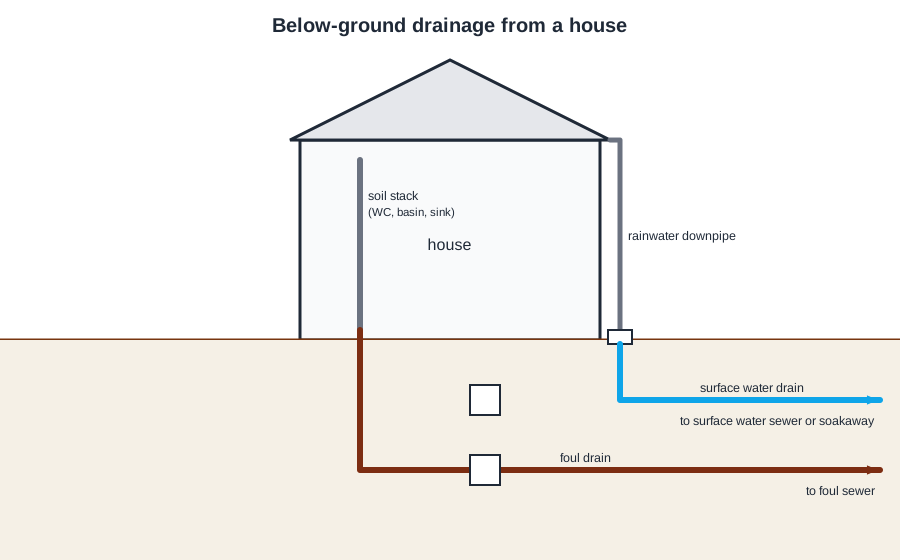
The rainwater downpipe runs to its own surface water drain and the soil stack to a foul drain; the two leave the site separately and never join. That is a separate system.
On an ascending spray bidet the nozzle sits in the base of the bowl, below the rim, so the spray head can end up submerged in dirty water. That makes it a fluid category 5 backflow risk and notifiable to the water undertaker before work starts, under Regulation 5 of the Water Supply (Water Fittings) Regulations 1999. A spray from a tap over the rim is the ordinary low risk pattern.
Sanitary appliances are made to receive and discharge soil, the waste from WCs and urinals, and wastewater from basins, baths, showers, sinks, washing machines and dishwashers. Surface water from paved areas is a rainwater matter under H3 and is kept out of the foul system where the drainage allows. Boiler condensate may be connected to sanitary pipework, but no appliance is designed around it.
Going further: the lessons behind this article
This article is the public answer. Unit 334 of the Level 3 course takes the same ground to the depth the exam and the synoptic assignment ask for, in 5 lessons:
- Occupancy, provision and the information a design starts from
- Selecting appliances and solving awkward layouts
- Activity space: sanitary accommodation people can use
- Combined, separate and partially separate drainage
- Fire stopping, access and notification
- Sanitation systems: the Unit 334 guide — every article on this unit in one place
- All PlumbMate articles — Level 1, 2 and 3
- The Level 3 course — the whole 8202-35 Diploma