A stack has been air tested three times on a Monday morning and it has failed three times. The fitter eventually pulls the plug at the base and finds a cement dropping the size of a fist sitting on it. Nobody looked before they pumped.
The short answer
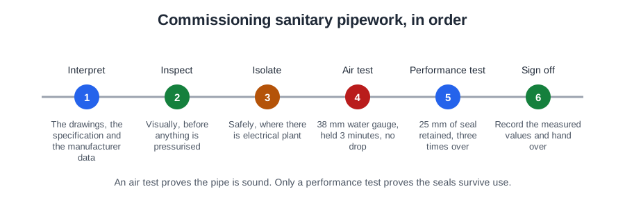
Commissioning is not a single test. It is a running order, and each stage depends on the one before it:
- Interpreting the information — the drawings, specification, standards and instructions that say what "right" looks like on this job.
- Visual inspection — walking the installation for open ends, damage, missing clips and anything left inside the pipe.
- Safe isolation — electrical and mechanical, before anyone works on a macerator, disposal unit or pumped line.
- Air testing — the soundness test, which proves the pipes, fittings and joints are airtight.
- Performance testing — discharging appliances together and measuring what is left in the traps.
- Setting up the appliances.
- Handing over.
Three of those tests ask three different questions, and all three are needed.
Three inspections, three questions
- The visual inspection asks: is it built the way it was designed? It finds open ends, damage, missing brackets, wrong falls and repairs still outstanding.
- The soundness test asks: is it airtight? A discharge system that leaks lets foul water and foul air into the building — and much of the pipework will be hidden behind boxing within days.
- The performance test asks: do the trap seals survive normal use? A system can be perfectly airtight and still pull every seal out the first time three appliances discharge together.
The order is not a habit, it is logic. There is no point pumping air into a stack that still has a rubble-filled branch; you will chase a leak the inspection would have found in a minute. And the performance test comes after the air test because a leaking joint bleeds pressure out of the stack and changes the pressures the traps see, so a performance result on an unsound system means nothing.
Setting up and handing over come last for a practical reason: the protective wrappings on sanitary appliances stay in place as long as practically possible, up to handover. Strip a basin at first fix and it gets chipped by the next trade.
The same running order applies whether you have installed a whole hotel stack or a single macerator. On a large or multi-storey job the tests may be done in sections, because a big system cannot always be tested in one go and parts of it are closed up before the rest is built. What never changes is that every part gets inspected, gets tested and gets recorded.
Interpreting the information
| Document | What it tells you |
|---|---|
| The drawings | Where the stacks, branches, vents, access points and appliances are, and what sizes they should be |
| The specification | Materials, tests required, pressures and durations, and the records the client wants |
| Approved Document H | Trap sizes and seal depths, branch limits, stack sizes, access, and the air test figures |
| BS EN 12056-2 | The code of practice, including National Annex NG — the inspection, the air test and the performance tests |
| BS EN 12056-5 | Installation and testing, and operating and maintenance instructions |
| BS 8000-13 | Workmanship: how the work should have been carried out, inspected, tested and recorded |
| Manufacturers’ instructions | The setting-up procedure for every appliance and powered component |
Sanitation work is not covered by Part H alone. Part H covers drainage and waste disposal; Part G sanitation, hot water safety and water efficiency; Part F ventilation, including bathroom extract rates; Part P electrical safety in dwellings, which is why the supply to a macerator matters to you. Knowing which Part answers which question saves a lot of argument on site.
For anything with a motor, a pump or a valve in it, the manufacturer's instructions are where the setting-up procedure lives. The standards tell you the general requirement; the instructions tell you the numbers for that model.
They also tell you what to do when something will not perform. If a component cannot reach the figures quoted in its own installation instructions, you do not adjust it beyond its settings or fit a second one alongside to make up the shortfall. You contact the manufacturer and agree how the problem is to be resolved. A tested and approved assembly stops being tested and approved the moment you modify it.
Not all the information is written down. On an existing building, ask what the system has done in the past — symptoms described by the user point you straight at the branch or appliance worth watching during the performance test. And on site, information on the position of gas, water, electrical and other services must be made available.
By the end of this stage you should be able to say, before you start work: which sections are to be tested and in what order; what test pressure and duration the specification calls for; which appliances are to be discharged; which components need isolating; and what records the client expects. Write it down. Those same headings become your commissioning record.
The visual inspection
On completion the discharge system should be meticulously inspected to make sure the recommendations have been observed, that no cement droppings, rubble or other objects are left in or on the pipes, and that no jointing material projects into the pipe bore. Only when that has been done are the tests made.
Solvent cement squeezed into the bore, a ring seal pushed out of its groove, a burr left on a cut end: each of them catches paper and grease and turns into a blockage six months after handover.
Inspection is not only at the end. Inspections and tests are made during installation as the work progresses, so the pipework is properly secured and clear of obstruction, and so that all work that is to be concealed is free from defects before it is finally enclosed. Where a section will be rendered inaccessible at a later stage, test completed work in sections. You do not wait for the whole job. You test that section now, while you can still reach it.
The walk round:
- All joints properly made — push-fit fully engaged, solvent-weld set and clean, ring seals in place.
- No open ends. Every branch, access point and pipe end capped or plugged.
- Adequate support: clips at the correct spacing, anchored securely, no sagging in near-horizontal runs.
- The designed fall on branch pipes, so waste drains completely and at a self-cleansing velocity.
- Swept connections facing the direction of flow.
- Traps fitted, correct for the appliance and filled with water.
- Appliances fixed securely, level and sealed to the structure.
- Access and rodding points reachable, and above the spillover level where they are in a stack.
- Cistern water levels correct; no cracked pans, chipped basins or scored plastics.
Clips are the item most often skipped on a walk round, and the one that fails first. Sanitary pipework is not part of the load-bearing structure and must be supported for the loads it carries, with no unauthorised attachments hung off it. Painting pipes to identify their contents, insisting every run is level, or expecting knuckle bends are not part of the check — discharge pipes need falls, and knuckle bends are avoided because they restrict the bore.
One more rule belongs here: prefabricated units should be tested at the works and inspected on delivery to site, so a fault built into a bathroom pod is found on the lorry rather than on the ninth floor.
Safe isolation
A macerator has stopped. You lift the lid to look at the impeller. Somewhere upstairs a tenant flushes, a float switch rises, and stainless steel blades spin up under your hand.
A macerator is fed from an unswitched fused spur, usually with a 5 A fuse; a disposal unit from its own spur, typically 10 A, commonly with 30 mA RCD protection.
- Tell the occupier what you are about to isolate, and agree it.
- Identify the circuit and the correct means of isolation.
- Switch off and remove the fuse from the spur.
- Switch off and lock off the circuit breaker at the consumer unit, and post a warning notice.
- Keep the fuse and the key on your person. They are no use hanging on a nail.
- Prove your voltage indicator on a known supply, test dead between all conductors, then prove the device again.
Flicking off the rocker switch and taping over it is not isolation, because a switch can be operated and a neon can lie. Turning the main switch off while somebody stands guard is not isolation either. The point of removing the fuse, locking off and keeping the key is that nobody can put the supply back on while you are inside the appliance.
Electrical isolation stops the motor. It does not stop water arriving. Mechanical isolation means closing and securing the water supply to the appliances that feed the unit, and making sure nobody discharges into the section you are working on — a notice on the door, and the floor agreed as out of use.
The electrical work is not yours to certify, but know what is expected: every installation is inspected and tested during erection and on completion before being put into service, inspection precedes testing and is normally done disconnected, and the dead tests — continuity, insulation resistance, polarity — come first, in order, before the installation is energised.
And check that the earth bonding to exposed metalwork is in place and has not been broken by your work, and that the fuse size and RCD protection match the instructions before the unit goes back into service.
The air test
Every discharge system inside a building is a sealed box holding foul air away from the people using the rooms. The joint you cannot see behind the boxing is the one that will let that air out.
| Test | Pressure | Duration |
|---|---|---|
| Air test, above ground sanitary pipework | 38 mm water gauge | at least 3 minutes |
| Air test, below ground drain up to 300 mm diameter | 110 mm water gauge to settle, then from 100 mm | about 5 minutes to settle, then losing no more than 25 mm in 7 minutes |
The number is not arbitrary. A trap seal is only 50 or 75 mm deep, and the pressure inside the pipework is held back by that water. Push the system much above 38 mm water gauge and the air simply blows the seals out through the appliances — the test destroys its own seal before it proves anything. 38 mm is a positive pressure every joint should hold comfortably while staying safely below the head the shallowest seal can resist.
That is also why raising the pressure to two or three times its normal value to "show up" a leak is wrong. It blows the seals, it can displace push-fit joints, and it tells you nothing about whether the system meets the requirement.
Three minutes is long enough for a real leak to show as a falling column in the manometer, and short enough that the temperature of the air does not move the reading on its own. Air warms as it is compressed and cools again, so a very short reading can mislead and a very long one drifts. The requirement is that the pressure remains constant: any steady drop is a leak.
An air test proves tightness and nothing else. It says nothing about branch lengths, falls, or whether the traps will survive a busy morning — that is the performance test's job.
To establish that an above ground system is sound, the test used is the air test. A dye trace and a CCTV survey belong to below ground drains, and soap solution is a way of locating a leak once the air test has already failed.
One habit is worth naming: test your gauge and hand pump on a short capped length of pipe before you go near the stack. A perished bulb or a split test hose will hold nothing, and you can spend an hour chasing a leak that is in your own equipment.
Why trap seals are performance tested
A basin smells. The pipework passed its air test six months ago and every joint is sound. The problem is not tightness; it is that the trap keeps losing its water when other people use the building.
Under working and test conditions traps retain a minimum seal of 25 mm of water. Twenty-five millimetres is not a comfortable margin; it is the least depth of water that will still stop foul air passing at the pressures a normal system develops. Below it, the trap is not a trap.
Three mechanisms, and the performance test is designed to provoke all of them:
- Self-siphonage. The appliance empties its own trap. A basin discharging into a 32 mm pipe fills it completely, forming a moving plug of water; behind the plug the pressure falls and the partial vacuum pulls the seal out after it.
- Induced siphonage. Where several appliances share a common branch, a plug of water from one drags the seal out of a passive trap that is not being used at all.
- Compression, or back pressure. A discharge falling down a stack compresses the air ahead of it, and near the foot that positive pressure blows the seal of a low-level branch back up into the appliance. The classic symptom is water bubbling up through a ground floor basin waste when somebody flushes upstairs.
Keep the distinction clean, because the two are cured differently. Siphonage pulls; compression pushes. If the water in the basin heaves up and bubbles, that is compression. If the trap is quietly empty and gurgles, that is siphonage.
The design rules exist to prevent all three — but a design is a prediction. Pipe gets routed round an unexpected steel, a fall gets flattened to clear a joist, a range of basins gets an extra one added. The performance test is the check that the system as built, not as drawn, still holds 25 mm in every trap.
And the workmanship version puts it more widely: check generally that all appliances drain speedily, quietly and completely. Slow, noisy or incomplete draining is a fault even when the seal survives.
Air admittance valves at commissioning
A cloakroom gurgles every time the basin empties. Behind the panel is an AAV screwed into the top of the branch, boxed in tight, with the plasterer's dust still on it. The valve is the right component in the wrong conditions.
AAVs are covered by BS EN 12380 — not BS EN 1329 (PVC-U pipes) or BS EN 274 (waste fittings and traps). Each condition is a diagnostic check:
- In an area which has adequate ventilation. A valve can only admit air that can reach it.
- Accessible for maintenance, and removable to give access for clearance of blockages.
- Not outside buildings, and not in dust-laden atmospheres.
- Not reducing the ventilation the below ground system needs, normally provided by open stacks. Where a system has no open ventilation at all, alternative arrangements to relieve positive pressures must be considered — an AAV admits air, it never releases it.
Fully boxing an AAV breaks two conditions at once: the valve is starved of air and it is no longer accessible. The remedy is not to remove the valve, and it is not to drill one small hole. Provide ventilation openings and an access panel in the boxing.
The ban on dust-laden atmospheres is mechanical: airborne fibres and lint clog the air inlet and the sealing face, and the valve stops admitting air. Condensation on the outside of the housing is not the cause, and positive pressure holding the diaphragm shut is what the valve is designed to do, not a fault. If a valve keeps blocking, the durable answer is to replace it with a stack vent pipe taken to open air — a second valve alongside doubles the problem, capping the stack removes the ventilation entirely, and a strainer below the valve does nothing about airborne dust.
And it must stand upright. An AAV seals and reopens correctly only when it is vertical. Fitted into a knuckle bend at the head of a stack it sits at an angle and the seat cannot close cleanly. The pipework is repositioned so the valve stands vertical — bracketing it, sealing round it or fitting a larger one all miss the point.
Macerators and disposal units
Where the position of a WC means a conventional stack cannot be installed, a macerator is the cheapest workable solution — cheaper than a second soil stack, a basement lifting station or rerouting the existing stack. But it is an appliance with a motor, a pump, a valve and a filter, so commissioning it proves more than a gravity branch ever needs to.
- There must also be access to a WC discharging directly to a gravity system, and the unit must meet BS EN 12050-1 or -3. A macerator is an addition, never the only WC.
- Inlet pipework must fall to it at not less than 1:40. A macerator does not suck.
- The outlet must rise at least 300 mm before any horizontal pipework, and there should be only one vertical lift, placed at the beginning of the run.
- Discharge pipework is solvent-weld plastic or copper. Push-fit ring seal PVC is not suitable, because a pumped line under pressure can push the joints apart.
- Changes of direction use smooth bends or two 45° bends, never a short radius knuckle.
- A non-return valve on the outlet stops effluent returning into the unit, and the supply is an unswitched fused spur wired to BS 7671.
Commissioning a WC macerator includes flushing the WC and timing the pump cycle: the unit should start on the discharge, run, clear the chamber and stop. Running cold water in until it overflows, air testing the unit to 1 bar or dismantling the outlet to spin the impeller are not commissioning steps.
With the unit running, every connection is checked for leaks — particularly a pan connector passing through a partition wall, which will be hidden the moment the wall is made good.
For a sink waste disposal unit, commissioning means proving the fixing and the seal to the sink, running it with water to prove flow and no leaks, and confirming the electrical work: the connection satisfies BS 7671, and the fuse is the size the manufacturer specifies.
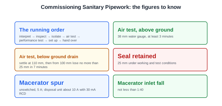
🔢 The numbers worth memorising
- The running order
- interpret → inspect → isolate → air test → performance test → set up → hand over
- Air test, above ground
- 38 mm water gauge, at least 3 minutes
- Air test, below ground drain
- settle at 110 mm, then from 100 mm lose no more than 25 mm in 7 minutes
- Seal retained
- 25 mm under working and test conditions
- Macerator spur
- unswitched, 5 A; disposal unit about 10 A with 30 mA RCD
- Macerator inlet fall
- not less than 1:40
- Macerator outlet
- rises at least 300 mm, one vertical lift, at the start of the run
- Macerator pipework
- solvent-weld or copper, never push-fit ring seal
- AAV standard
- BS EN 12380; mounted vertical, ventilated, accessible, removable
- Boxed AAV remedy
- ventilation openings and an access panel
- Persistently blocked AAV
- replace with a vent pipe to open air
⚠️ Where people go wrong
- Air testing before anybody has looked inside the pipe.
- Running the performance test on a system that has not passed the air test.
- Stripping the protective wrappings off appliances at first fix.
- Waiting for the whole job before testing a section about to be boxed in.
- Adjusting a component beyond its settings, or doubling it up, when it will not meet its figures.
- Skipping the clips on a walk round. They are the item that fails first.
- Taping over a spur switch and calling it isolation.
- Isolating electrically and forgetting that water can still arrive.
- Raising the test pressure to “show up” a leak. It blows the seals.
- Quoting 100 mm water gauge for above ground pipework. That is the drain figure; above ground it is 38 mm.
- Treating a passed air test as proof the traps will hold.
- Boxing an AAV in tight, or fitting one into a knuckle bend so it sits at an angle.
- Fitting a second AAV where one keeps blocking.
- Fitting a macerator as the only WC, or on push-fit ring seal pipework.
- Calling an overflow-fill or a 1 bar air test a macerator commissioning step.
📝 10-Question Self-Test
Straight from the Level 3 course question bank. Click an option to see whether you got it right — the explanation appears instantly, and there is nothing to submit.
Air admittance valves are made and tested to BS EN 12380, and Approved Document H paragraph 1.33 allows a stack to terminate inside a building only where the valve complies with it. BS EN 1329 covers PVC-U pipes and fittings and BS EN 274 covers waste fittings and traps, which is why both look plausible on a sanitation question.
A valve can only admit air that can reach it, and Approved Document H paragraph 1.33 requires an air admittance valve to be in an area with adequate ventilation and to stay accessible for maintenance. Boxing it in tight starves it, so the boxing needs ventilation openings and an access panel. Sealing every joint with mastic does precisely the opposite of what the valve needs.
An AAV only seals and reopens correctly when it stands vertical; mounted off a knuckle bend it will not seat. The pipework is altered so the valve sits upright.
The commissioning records are the proof that the system was tested and performs as designed; delivery notes, an installation manual and a quotation are commercial or descriptive papers that record no test results.
Safe isolation is not finished when the fuse is out and the breaker locked. Remove the fuse, lock off, post a notice and keep the fuse and key on your person, then prove the conductors dead at the point of work with an indicator proved immediately before and after, as HSR25 paragraph 72 requires.
Handover means leaving the instructions, explaining the operation and telling the customer what routine maintenance the unit needs and what must never go down it.
The fixed wiring and connection of any appliance, including a waste disposal unit, must comply with BS 7671; BS EN 60335 is the appliance construction standard.
A commissioning record documents the work that was done and tested: the date and time, who installed and tested it, where the system is, the components fitted, and the soundness and performance test results. The completion date and the installers’ names are exactly that. Delivery notes prove a purchase, not a test, and the building control officer’s name is not commissioning data.
NG.3.1.1 states that to ensure a satisfactory air seal at the base of the stack, or at the lowest plug or bag if only a section is being tested, a small quantity of water sufficient to cover the plug or bag can be allowed to enter the system. The trap seals are charged separately by filling the appliances, and the manometer is connected through a tee piece or a flexible tube passed through a trap.
BS EN 12056-2 NG.3.1.3.1 says smoke testing of plastics pipework should be avoided because naphtha has a detrimental effect, particularly on ABS, PVC-U and MUPVC, and Approved Document H paragraph 1.38 says smoke testing is not recommended for PVC-U. NG.3.1.3.2 and BS 8000-13 clause 4.1.1 describe applying soap solution to suspect joints under internal pressure, with leaks shown by bubbles. A whole-system water test is not justified.
Going further: the lessons behind this article
This article is the public answer. Unit 334 of the Level 3 course takes the same ground to the depth the exam and the synoptic assignment ask for, in 8 lessons:
- Commissioning sanitary pipework: the stages and what each proves
- Interpreting the information before commissioning starts
- The visual inspection: what a completed system must show
- Safe isolation before working on powered sanitary components
- The air test requirement: 38 mm water gauge for 3 minutes
- Why trap seals are performance tested: siphonage and compression
- Air admittance valves: the conditions they need to work
- Macerators and waste disposal units: what commissioning must prove
- Sanitation systems: the Unit 334 guide — every article on this unit in one place
- All PlumbMate articles — Level 1, 2 and 3
- The Level 3 course — the whole 8202-35 Diploma