Six flats over three storeys share one stack. The architect has drawn a 100 mm stack. Is that right, or lucky?
The short answer
You can prove it in three steps, and the formula is short:
Qww = K × √∑DU
Add up the discharge units, take the square root, multiply by the frequency factor. K is 0.5 for a dwelling, 0.7 for a hospital or school, 1.0 for public toilets, 1.2 for special use.
Branches are sized differently — not by calculation but by a table where diameter, length and gradient trade against each other.
The four systems, and which one you use
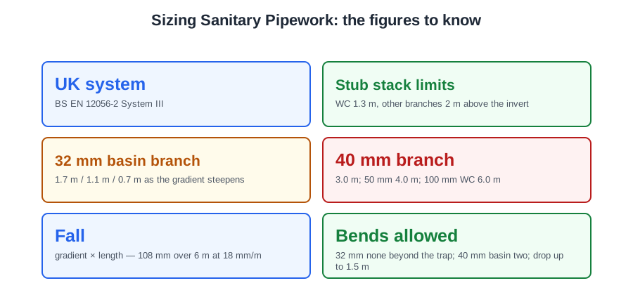
BS EN 12056-2 recognises four sanitary pipework systems, I to IV, and the one used in the United Kingdom is System III: a single discharge stack with each appliance connected by its own separately ventilated or unventilated branch, each branch running full bore only briefly. Every table you use for branches and stacks in this country is the System III column.
Primary ventilated stack. The standard domestic arrangement and the cheapest, because there are no separate ventilating pipes at all — the discharge stack itself acts as the vent. It works only if the appliances are closely grouped around the stack. To keep it working: P traps with the discharge pipe the same diameter as the trap; bends and branches avoided; and the stack as straight as possible with a large radius bend, or two 45° bends, at the base.
Ventilated branch. Where a branch cannot meet the unventilated limits, that branch gets its own branch ventilating pipe, connected close to the trap so air enters behind the discharging water. Only the branches that need it are ventilated; the stack itself is still a single discharge stack.
Secondary ventilated stack. A second vertical pipe alongside the discharge stack, cross-connected to it. Only the main discharge stack is ventilated, and that is the whole point: it acts as a safeguard against positive and negative air pressure fluctuations, so trap seal loss is reduced. Water falling down a busy stack drags air with it, creating suction above and back pressure below; the parallel vent gives that air an easier route. It is only likely to be preferred where the number of appliances and their distance from the stack are large. On a house it is expense for nothing.
Stub stack. A short unventilated stack serving ground floor appliances only, closed at the top with an access cover or AAV. Allowed where all of the following are true: it connects into a ventilated discharge stack or a ventilated drain not subject to surcharging; no connected WC has a floor level more than 1.3 m above the invert; and no other branch enters with its centre line more than 2 m above that invert.
| Layout | System to use |
|---|---|
| Appliances closely grouped, short branches | Primary ventilated stack |
| One or two branches too long or too bendy | Ventilated branch on those branches |
| Many appliances, long branches, tall building | Secondary ventilated stack |
| Ground floor appliances only, close to the drain | Stub stack |
Branch discharge pipes
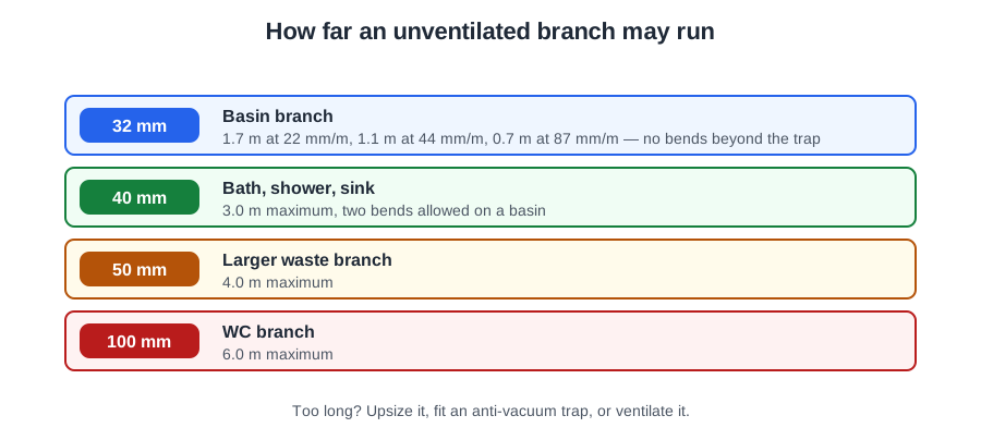
A basin moved to the far end of a bathroom, now 2.4 m from the stack, still in 32 mm. Every time it empties the trap gurgles and the seal drops. Nothing is blocked — the branch is simply too long for its diameter.
Make the pipe steeper and the water runs faster, filling the bore and pulling air behind it; the permitted length then falls. Make the pipe bigger and it never runs full, so it can be longer.
| Appliance | Min. pipe size | Max. length | Gradient |
|---|---|---|---|
| Wash basin or bidet | 32 mm | 1.7 m | 18 to 22 mm/m |
| Wash basin or bidet | 32 mm | 1.1 m | 18 to 44 mm/m |
| Wash basin or bidet | 32 mm | 0.7 m | 18 to 87 mm/m |
| Wash basin or bidet | 40 mm | 3.0 m | 18 to 44 mm/m |
| Bath, shower or kitchen sink | 40 mm | 3.0 m | 18 to 90 mm/m |
| Two to four wash basins | 50 mm | 4.0 m | 18 to 44 mm/m |
| WC, outlet over 80 mm | 100 mm | 6.0 m | 18 mm/m minimum |
The basin in the story needed a 40 mm pipe from the start. And for a WC branch, take 6 m at 18 mm/m or more as the working limit — so a WC 8 m from the stack needs a branch ventilating pipe.
Gradient is quoted in millimetres of fall per metre, so the total drop is gradient × length. A 6 m soil pipe at 18 mm/m drops 108 mm over its full length. Set your levels from that figure: 1080 mm would be a ski slope and 36 mm would not shift the solids. Run it the other way too — a 3 m, 40 mm sink waste with 60 mm of fall available is 20 mm/m, inside the 18 to 90 band, so the branch is fine.
Length is not the only limit. A 32 mm basin branch is allowed no bends other than the connection bend at the trap, and no vertical drop. A 40 mm basin branch may have two bends. Bath, shower, sink and WC branches allow more bends and a vertical drop of up to 1.5 m.
Connections: junctions on branches of about the same diameter get a 25 mm radius sweep or 45°; branches of 75 mm or more joining an equal stack get 50 mm minimum radius or 45°; branches up to 40 mm joining branches of 100 mm or more connect to the upper part of the pipe wall; and no branch may discharge so as to cause crossflow into another opposite it.
When a branch is too long
Every trap holds a plug of water — a minimum of 25 mm of seal under working and test conditions — and that plug is all that stands between the room and the drain. Pressure is what takes it away:
- Self siphonage — the appliance's own discharge fills the branch, and the moving plug creates a partial vacuum behind it. Basins are the classic victims.
- Induced siphonage — another appliance discharges and empties the seal of a trap that was not even being used.
- Back pressure — air trapped ahead of falling water at the base of the stack pushes the seal back up and out.
- Evaporation, and capillary attraction where a thread or rag hangs over the trap weir.
A branch that has broken the limits has three remedies, and any one of them can be the right answer:
- Increase the pipe diameter to the next size up, so the branch no longer runs full.
- Fit an anti-vacuum or resealing trap.
- Ventilate the branch.
So a 40 mm sink waste that has crept past 3 m can be upsized to 50 mm, given an anti-vacuum trap, or ventilated. The 8 m WC branch, already at 100 mm, gets a branch ventilating pipe.
That pipe: connected within 750 mm of the trap; connected at the other end above the highest spillover level of the appliances served; given a continuous incline so condensation drains back; 25 mm minimum, rising to 32 mm where the branch is longer than 15 m or has more than five bends; and if it runs direct to outside air, finishing at least 900 mm above any opening within 3 m.
An air admittance valve to BS EN 12380 lets air in but seals against foul air coming out, so it can terminate a stack or branch vent inside. It must be above the spillover level of the highest appliance served, accessible and removable.
But note the limit: an AAV relieves suction and does nothing about positive pressure. Where a system has no open ventilation at all, alternative arrangements to relieve positive pressures have to be considered, and stacks connected to drains liable to surcharging need a ventilating pipe of not less than 50 mm connected to the base of the stack above the likely flood level.
Discharge units and the frequency factor
A single house rarely needs sizing: one WC puts you on a 100 mm stack whatever else is connected. Sizing earns its keep on flats, halls of residence, offices and public buildings.
Appliances do not all discharge alike, and they never all discharge at once. So each appliance is given a discharge unit (DU), a loading value in litres per second used only for calculation. BS EN 12056 is the document that lists them — not BS 6465, not BS 8000-13, not Approved Document G.
| Appliance | DU, System III (l/s) |
|---|---|
| Wash basin, bidet | 0.3 |
| Shower without plug | 0.4 |
| Shower with plug | 1.3 |
| Bath | 1.3 |
| Kitchen sink | 1.3 |
| Dishwasher (household) | 0.2 |
| Washing machine up to 6 kg | 0.6 |
| Washing machine up to 12 kg | 1.2 |
| WC with 6.0 litre cistern | 1.2 to 1.7 |
| WC with 9.0 litre cistern | 1.6 to 2.0 |
The WC values are a range because they depend on the pan type. Take the higher figure unless you have manufacturer's data.
The same appliances behave differently in different buildings — a basin in a house is used a few times an hour; a basin in a stadium concourse is used continuously at half time. That is what the frequency factor accounts for, and it is why how frequently the appliances are used affects the stack size — not the water temperature, the height above sea level or the incoming main pressure.
Two rules go with the formula. Continuous flows and pumped discharges are added on without any reduction. And the pipe capacity chosen must be at least the larger of the calculated flow rate or the flow rate of the single appliance with the largest discharge unit — a stack serving one WC cannot be smaller than that WC needs.
A flat with one 6 litre WC (1.7), a bath (1.3), a basin (0.3), a sink (1.3) and a 6 kg washing machine (0.6):
∑DU = 5.2; √5.2 = 2.28; K = 0.5; Qww = 1.14 l/s.
Sizing the stack: the worked example
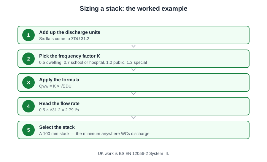
Step 1. Six flats at 5.2 each gives ∑DU = 31.2.
Step 2. Flats are intermittent use, K = 0.5.
Qww = 0.5 × √31.2 = 0.5 × 5.59 = 2.79 l/s
Step 3. Read the stack table. Swept entries are used in the United Kingdom, so read that column and take the first capacity equal to or above your flow rate.
| Stack DN (mm) | Q max, square entries (l/s) | Q max, swept entries (l/s) |
|---|---|---|
| 70 | 1.5 | 2.0 |
| 80 | 2.0 | 2.6 |
| 90 | 2.7 | 3.5 |
| 100 | 4.0 | 5.2 |
| 125 | 5.8 | 7.6 |
| 150 | 9.5 | 12.4 |
| 200 | 16.0 | 21.0 |
Going down the swept column, 2.6 l/s at DN 80 is too small and 3.5 l/s at DN 90 is the first value above 2.79. But there is a footnote: 100 mm is the minimum size where WCs are connected in System III. The answer is a 100 mm stack, with 5.2 l/s of capacity against 2.79 of demand. The architect was right, and now you can prove it.
Where the stack is secondary ventilated the capacities rise: a 100 mm stack with a 50 mm secondary vent carries 7.3 l/s with swept entries.
Approved Document H Table 3 gives the same answer in simpler form, and it is the Building Regulations figure to quote:
| Stack size (mm) | Max. capacity (l/s) |
|---|---|
| 50 (no WCs) | 1.2 |
| 65 (no WCs) | 2.1 |
| 75 (max. 1 WC, outlet under 80 mm) | 3.4 |
| 90 | 5.3 |
| 100 | 7.2 |
Alongside it, fixed minimums: urinals not less than 50 mm; closets with outlets under 80 mm not less than 75 mm; closets with outlets over 80 mm not less than 100 mm. A stack must never reduce in the direction of flow, and its internal diameter must be at least that of the largest trap or branch connected.
A correctly sized stack still fails if it is badly arranged. The bend at the foot should have as large a radius as possible and at least 200 mm at the centre line; no branch may connect lower than 450 mm above the invert of the tail of that bend in single dwellings up to three storeys. Offsets in the wet part are avoided; where unavoidable in a building of not more than three storeys, no branch connection within 750 mm of the offset. The dry stack vent may be reduced in one and two storey houses, but never below 75 mm.
The finished design is proved by the stack performance test, and it does not discharge everything on the stack. For domestic use with 1 to 9 appliances of each kind: one WC, one wash basin and one sink, rising to two of each on a stack serving 36 or more. Those appliances should be close to the top of the stack and on adjacent floors, because that gives the worst pressure conditions. Baths, showers and spray-tap basins need not normally be discharged. Afterwards every trap must retain at least 25 mm of seal, and the test is repeated three times with the traps recharged.
Materials, drawings and quotations
| Material | Standard |
|---|---|
| PVC-U | BS EN 1329 |
| Polypropylene (PP) | BS EN 1451 |
| ABS | BS EN 1455 |
| Polyethylene (PE) | BS EN 1519 |
| PVC-C | BS EN 1566 |
| Cast iron | BS 416, BS EN 877 |
| Copper | BS EN 1254, BS EN 1057 |
| Galvanised steel | BS 3868 |
| Traps | BS EN 274, BS 3943 |
Material choice is a design decision, not a habit. Plastics dominate because they are light, cheap and easy to join, but they expand and contract, so pipes must be firmly supported without restricting thermal movement. Cast iron is chosen where noise matters, in flats and where a stack runs past a bedroom. Where different metals meet, separate them with a non-metallic material to prevent electrolytic corrosion, and take care that any earth bonding remains continuous.
One easily forgotten rule: sanitary pipework connected to WCs should not allow light to be visible through the pipe wall, because a translucent pipe is believed to encourage rodents to gnaw at it. Workmanship follows BS 8000-13.
To show a customer how the pipework will be laid out, the right document is a line drawing that is not to scale. A full set of CAD drawings tells them nothing, and the manufacturer's manual and the bill of quantities tell them less.
A good one shows each appliance in position and labelled with the stack as a single vertical line; writes the diameter and the length against every branch, and the gradient where it matters; marks traps, seal depths, ventilating pipes and any AAV; marks the access points so the customer knows what must stay reachable; and carries a title, a date and a revision. Because it is not to scale, nobody can measure off it — which is exactly the point: the drawing communicates the arrangement, and the written dimensions carry the design.
A quotation is a fixed price for defined work; an estimate is a considered guess. For a small dwelling it shows: the customer's name and address and your own business details; the make and model of every appliance and fitting included; the work covered and, clearly, the work not covered — making good, tiling, decoration, electrical connection; start and end dates and any disruption to expect; the price, how VAT is treated and how long the quotation stands; and scheme membership or a note that Building Control will be notified.
Attach the line drawing to the quotation. Together they answer the two questions a customer actually has: what am I getting, and what will it cost.
🔢 The numbers worth memorising
- UK system
- BS EN 12056-2 System III
- Stub stack limits
- WC 1.3 m, other branches 2 m above the invert
- 32 mm basin branch
- 1.7 m / 1.1 m / 0.7 m as the gradient steepens
- 40 mm branch
- 3.0 m; 50 mm 4.0 m; 100 mm WC 6.0 m
- Fall
- gradient × length — 108 mm over 6 m at 18 mm/m
- Bends allowed
- 32 mm none beyond the trap; 40 mm basin two; drop up to 1.5 m
- Three remedies
- upsize, anti-vacuum trap, or ventilate
- Branch vent
- within 750 mm, 25 mm (32 mm over 15 m or five bends)
- Surcharged drain
- vent not less than 50 mm at the base of the stack
- The formula
- Qww = K × √ΣDU
- Frequency factor
- 0.5 dwelling, 0.7 school or hospital, 1.0 public, 1.2 special
- Six flats worked
- ΣDU 31.2 → 2.79 l/s → a 100 mm stack
- Minimum with WCs
- 100 mm in System III
- 100 mm stack capacity
- 5.2 l/s swept; 7.2 l/s in Approved Document H
- Base bend
- 200 mm centre line radius; lowest branch 450 mm above the invert
- Stack test
- one WC, one basin, one sink; three times, traps recharged, 25 mm retained
⚠️ Where people go wrong
- Reading a System I or II column. The UK uses System III.
- Fitting a stub stack into a drain subject to surcharging.
- Assuming a steeper branch may run further. The permitted length falls.
- Reaching for a vent when upsizing the branch, or an anti-vacuum trap, would do.
- Putting a bend or a drop in a 32 mm basin branch.
- Expecting an AAV to relieve positive pressure. It only admits air.
- Taking discharge units from BS 6465 or Approved Document G. They are in BS EN 12056.
- Forgetting to square-root the sum before applying K.
- Adding continuous or pumped flows into the square root. They are added on afterwards.
- Reading the square entry column. UK work is swept.
- Taking DN 90 at 3.5 l/s. With WCs connected the minimum is 100 mm.
- Reducing a stack in the direction of flow, or a stack vent below 75 mm.
- Discharging every appliance in a stack performance test.
- Using a translucent pipe on a WC connection.
- Handing a customer CAD drawings. They need a not-to-scale line drawing.
- Writing a quotation without naming what is excluded.
📝 10-Question Self-Test
Straight from the Level 3 course question bank. Click an option to see whether you got it right — the explanation appears instantly, and there is nothing to submit.
BS EN 12056-2 sizes the stack from Qww = K × the square root of the sum of the discharge units, and K is the frequency factor set by how the appliances are used: 0.5 for intermittent use in a dwelling or office, 0.7 for frequent use in a school or hotel, 1.0 for congested public use. Water temperature and incoming main pressure play no part in the calculation.
A line drawing that is not to scale is the convention for presenting a sanitary pipework design to a customer: the stack as a single vertical line, each appliance labelled in position, and diameters, lengths and gradients written against every branch. A full CAD set is aimed at the installer and building control, and most customers cannot read one, so it explains nothing.
Approved Document H Table 3 allows a 75 mm stack, with a maximum capacity of 3.4 litres per second, but the note against it limits that stack to not more than one WC with an outlet under 80 mm. Add a second WC and you are back to 100 mm. The close-coupled type is the tempting answer, but the shape of the pan makes no difference; the number of WCs decides it.
Discharge units, the loading value in litres per second given to each appliance, are listed in BS EN 12056-2, and in the United Kingdom you read the System III column. BS 6465-1 is the tempting one because it is a sanitary standard, but it sets how many appliances a building needs, not the flow each one contributes to the pipework.
Branch discharge pipes are laid at a uniform gradient, and BS EN 12056-2 ND.3.2.2 puts the practical minimum at 18 to 22 mm/m; Approved Document H Table 2 allows 18 to 44 mm/m on a 40 mm pipe. 22 mm/m sits comfortably inside that. 8 mm/m is the tempting one, but it is too flat to be self-cleansing, and 110 mm/m is far outside any limit in the table.
Each appliance carries a discharge unit value; add them up and the total feeds Qww = K × √ΣDU, which gives the flow the pipework has to carry. That flow is then read against the stack table to fix the stack size, so the discharge unit total sizes the soil stack. Branch gradients come from the branch discharge pipe tables, not from a DU total.
The drop is the fall per metre multiplied by the length: 18 mm/m x 6 m = 108 mm.
An air admittance valve must sit above the flood level of the highest appliance on the stack so that a blockage cannot back foul water up to the valve, and it must be accessible.
A pumped discharge pipe longer or higher than the unit is rated for adds friction the pump cannot overcome quickly, so the pump runs on after the appliance has emptied, and may fail to clear the pipe at all.
The bend at the foot of the stack should have as large a radius as possible and at least 200 mm at the centre line.
Going further: the lessons behind this article
This article is the public answer. Unit 334 of the Level 3 course takes the same ground to the depth the exam and the synoptic assignment ask for, in 6 lessons:
- System types: primary ventilated, ventilated branch and secondary ventilated
- Branch discharge pipes: diameter, length and gradient
- When a branch is too long: ventilating pipes and air admittance valves
- Discharge units, frequency factors and the flow rate formula
- Sizing a discharge stack: a worked example
- Materials, line drawings and quotations for a dwelling
- Sanitation systems: the Unit 334 guide — every article on this unit in one place
- All PlumbMate articles — Level 1, 2 and 3
- The Level 3 course — the whole 8202-35 Diploma