A tenant rings the office. The downstairs cloakroom, she says, smells of drains. That is the whole message — and it could be four completely different faults.
The short answer
Guessing costs money, so the first move is not a tool at all. The end user has been watching the fault for far longer than you ever will, and ten minutes on the doorstep usually saves an hour with the panels off. The conversation comes before the design drawings, before the wholesaler and long before you isolate and strip an appliance.
Then two complaints cover almost everything: it smells, or it will not go away. A smell means foul air is passing a seal, a leak or a component. Slow running means the pipe cannot carry the flow. They point in opposite directions.
What to ask
- What exactly happens, and where? A smell, a gurgle, a slow empty and a back-up in the bowl are four different faults.
- Which appliance, and is anything else affected? One trap emptying points at one branch; every ground-floor trap bubbling points at the stack or the drain.
- When did it start, and how often? A fault that appears only now and then is intermittent, and intermittent faults are almost always caused by something else being used at the same time.
- Does it happen every time, or only when another appliance is used? This one question separates a trap that empties itself from a trap emptied by its neighbours.
- Has anything changed? A new washing machine, a vent capped off by another trade, a wet room upstairs.
- Is the appliance used at all? A rarely used en-suite basin, or a plant room floor gully, may simply have dried out.
Some replies are worth more than any test. Floor drains connect to branches of DN 80 or larger, so they are not subject to self-siphonage — but infrequent use can lead to total loss of seal by evaporation. So when the occupier of a plant room confirms nothing has discharged into the gully for weeks, the diagnosis is made on the doorstep.
Timing is evidence too. Seals that blow only during heavy rain point to a surcharged drain interrupting the airflow down the stack. Trouble only on windy days points to wind effects at the vent terminal. Trouble only first thing in the morning, in a block of flats, points to flow load on the stack.
But what the end user tells you is a lead, not a conclusion. Look into the trap, run the appliance and watch it empty, and have somebody discharge the appliance the customer says is involved while you listen at the faulty one. Where the account and the evidence disagree, the evidence wins.
Once you have a diagnosis, the end user needs your findings in plain words, with the cost, timescale and disruption spelled out before work starts. And foul water is a biological hazard, so the visit needs a risk assessment and the right PPE: gloves, eye protection and a means of washing.
Manufacturer data and documented history
A wastewater lifter keeps tripping. You could open it and start guessing. Two better documents are usually within reach.
For fault finding on a lifting unit, the reference source is the manufacturer's fault-finding flow chart. It asks a yes or no question, and each answer sends you to the next check, so the plant is tested in a safe and logical order. No British Standard can do that job, because designs vary — BS EN 12056-2 tells you how the pipework should have been designed, and a WRAS directory only tells you a fitting is approved. None of them knows why this pump trips.
Manufacturer information is wider than a fault chart: the correct fuse or spur rating, spares and seal kits, service intervals, the de-jamming tool, and fitting details. It also gives templates — a countertop wash basin is supplied with a cutting template, because the bowl is dropped through a cut-out.
Air admittance valves are a case where the standards send you straight back to the maker: the installation of AAVs should comply with the manufacturer's instructions, and the valves themselves comply with BS EN 12380.
The documented history tells you whether the fault is new or a repeat. A log should be kept of all maintenance work, detailing what was carried out. And commissioning must be recorded in writing, including the setting of the motor overload switch and the readings from hours-run meters. That is the baseline: if a motor now cuts out on overload, the record tells you whether the setting has been altered or the plant has simply run far more hours than it should.
| Source | What it settles |
|---|---|
| End user | Symptoms, timing, what changed |
| Manufacturer’s fault-finding flow chart | The order of checks on that make and model |
| Manufacturer’s instructions | Ratings, spares, templates, AAV siting |
| Maintenance log | Repeat faults and previous repairs |
| Commissioning record | Overload setting and hours run when new |
| As-fitted drawings | Where the access points and pipe runs are |
Smells and slow running
All points of discharge are fitted with a trap, and under working and test conditions traps retain a minimum seal of 25 mm of water or equivalent. The phrase "or equivalent" matters, because some appliances use a waterless seal.
A smell has three possible routes:
- The trap is not holding its seal — siphoned, blown, evaporated or wicked away. By far the most common cause.
- The pipework is leaking. A cracked pipe, failed joint or perished ring seal lets both water and air out; over time it shows as staining, moss or mould near the pipe.
- A component is letting air past — an AAV that will not reseat, a lifting plant whose tank vent has been capped off, an access cap left loose.
Slow running says the pipe cannot pass what it is being given: a blockage, a pipe that is undersized, a fall that is too shallow, or a sag where the pipe has lost its support.
Take a bath slow to empty. The most suitable next step is to strip out the trap and check it for blockages — nearest the appliance, likeliest place for hair and soap, and it comes apart in two minutes. Rodding the main drain is the wrong end of the system to start at, fitting a larger waste would break the design rules and would not remove the obstruction, and an AAV cures a pressure problem, not a blockage.
Two sounds separate a pressure fault from a blockage. A gurgle as an appliance finishes emptying is air being pulled through the seal: siphonage. A bubble or a blow, where air pushes up through the trap into the bowl, is positive pressure in the stack. Neither is a blockage, and neither is cured by rodding.
| Complaint | Points to | First check |
|---|---|---|
| Smell, one appliance, rarely used | Seal lost by evaporation | Look into the trap |
| Smell, damp or staining nearby | Leak on pipe or joint | Soundness test that section |
| Smell from a loft or duct | AAV not reseating | Manufacturer’s instructions and the valve |
| Slow to empty, one appliance | Blockage at or near the trap | Strip the trap out |
| Gurgle at end of own discharge | Self-siphonage | Branch length, size and fall |
| Bubbling when others discharge | Back pressure in the stack | Foot bend, offsets, drain |
The six causes of seal loss
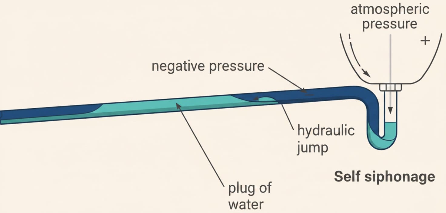
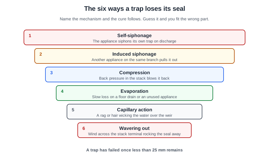
An empty trap is one symptom with six common causes, and each one leaves a different pattern behind.
Self-siphonage occurs when the branch discharge pipe flows at full bore: the plug of water leaves a negative pressure behind it. A basin on a 32 mm branch 2.5 m long with no vent is the classic case — the limit is 1.7 m. The telltale is that the trap is emptied by its own discharge, and the neighbours are unaffected.
Induced siphonage empties traps on appliances not discharging. Picture three basins on a common 50 mm branch: the one nearest the stack holds its seal when emptied alone, but loses it whenever the two upstream basins are emptied together. That pattern rules self-siphonage out.
Back pressure. Positive pressures occur above offsets and bends in stacks, blowing foul air through the seal. Ground-floor traps that bubble when the flats above discharge together are the classic symptom. Sharp bends at the base of a stack cause large back pressures, which is why the foot bend needs at least 200 mm centre-line radius. Two other conditions give the same symptom: a surcharged drain interrupting the airflow, and an interceptor trap close to the foot of the stack. Both may need additional ventilation — not less than 50 mm at the base of stacks on drains liable to surcharging.
Then the quiet three:
- Evaporation. Nothing discharges, the water dries away. No noise and nothing else wrong.
- Capillary attraction. A strand of hair or fibre lodges over the weir and wicks the water out drop by drop. One trap only, and you can usually see the strand.
- Wavering out. Wind across the roof produces pressure fluctuations near parapets and corners; the seal rocks until it spills over the weir. Windy days only.
Two more mechanisms are worth knowing. Momentum loses a seal when a very large volume is tipped straight down the outlet. Foaming from excessive detergent backs up the pipes and soaks the seal away.
| Cause | Telltale pattern |
|---|---|
| Self-siphonage | Only the appliance that just discharged |
| Induced siphonage | A trap that was not discharging; fine when used alone |
| Back pressure | Bubbling and blowing, lowest floor, others discharging |
| Evaporation | Rarely used appliance, whole seal gone, silent |
| Capillary attraction | One trap, slow, a strand over the weir |
| Wavering out | Windy days, exposed terminal |
Measuring the branch
When the pattern says siphonage or slow running, four numbers settle most of it: the trap, the pipe size, the length of the branch and its fall.
So a domestic food waste disposal unit draining slowly through a 32 mm trap with a 50 mm seal has an undersized trap: it requires 40 mm with a 75 mm seal (50 mm with 75 mm for an industrial-type unit).
The type of trap matters as much as the size. A disposal unit should discharge through a tubular S trap — smooth and full bore, so it will pass ground food waste. Bottle traps should only be used with wash basins, so a resealing bottle trap is the wrong choice. And an interceptor trap is not a waste connection at all: it belongs in a below-ground drain, and one close to a stack causes large pressure fluctuations.
Three rules apply to every trap: no reduction in cross-sectional flow area through it, no more than one trap on the discharge pipework from any appliance, and it should be removable for cleaning. A shower trap may sit up to 750 mm from the waste outlet.
The gradient of a branch discharge pipe should be uniform, and practical considerations usually limit the minimum to 18 or 22 mm/m. Flatter gradients down to 9 mm/m may be imposed only on long runs of DN 100 and DN 150 where space is restricted, and then only with a design flow of not less than 2.5 l/s and high-quality workmanship.
So a shower waste laid at 22 mm/m is acceptable; 8 mm/m is too flat to be self-cleansing, and 110 mm/m is nowhere near any limit in the table.
Two more checks. Oversizing branch pipes to avoid self-siphonage is uneconomic and increases the rate of deposit accumulation — so a bigger waste is not a cure. And bends should be avoided, especially on wash basins, as they cause blockages and increase self-siphonage; where unavoidable they should be of large radius.
Air admittance valves
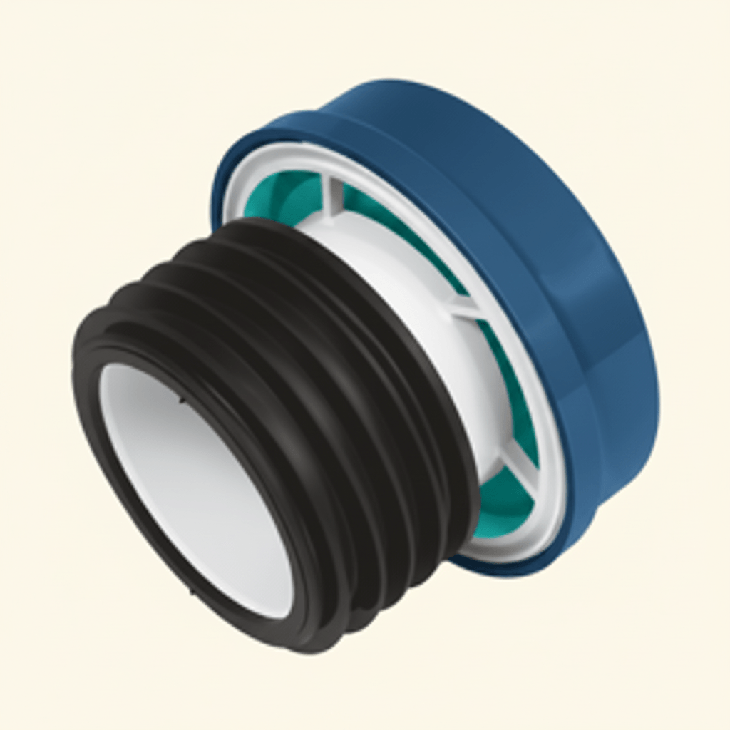
Each line of the AAV rules is a diagnostic check:
- In an area with adequate ventilation. A sealed boxing starves it of air.
- Accessible for maintenance and removable to give access for clearance of blockages.
- Not outside buildings, where moisture and frost can hold the diaphragm open or shut.
- Not in dust laden atmospheres — dust from industrial processes may cause AAVs to malfunction.
In a joinery workshop, sawdust settling on the seat stops the diaphragm reseating, so the valve leaks foul air into the room. That is the fault, not the fact that the valve sits above spill-over level or in a ventilated space, both of which are correct practice.
The one thing an AAV cannot do is relieve positive pressure. So in a new terrace of four houses where every stack is terminated internally with an AAV, nothing on the drain is open to the atmosphere: the first surge of flow raises the pressure in the drain, and the lowest traps in all four houses blow. The cure is open ventilation somewhere on the system, normally a stack carried up and out at or near the head of the drain run.
Because it must be removable, an AAV doubles as an access point: lifting it lets you look into the stack and gives a rodding access. One warning though — AAVs should be removed before a kinetic ram gun is used, because undue pressure and blowback may cause malfunction, and where AAVs are permanently fixed, ram guns should not be used at all.
Macerators and lifting plants
Work in a fixed order: safe isolation first, then the manufacturer's fault-finding flow chart, then the written history.
- Runs for a long time after flushing → a blockage in or around the pump.
- Pump fails to run after a discharge → the fuse in the spur, and the float or level switch.
- Slow discharge from the pan with the pump running correctly → on a macerator, often a blocked carbon air filter: the unit cannot breathe.
- Runs, stops, restarts a few seconds later without being flushed, and the tank refills between runs → short cycling from a non-return valve that is not seating. Pumped water in the rising main drains back into the tank, lifts the level switch and restarts the pump.
- Switches on and off repeatedly for almost nothing → look upstream, not inside. A dripping tap or leaking joint keeps refilling the chamber a little at a time.
- Sluggish discharge with an odour from the tank → check the vent. Faecal lifting plants shall be ventilated to above roof level. A capped vent means the tank cannot breathe, so filling is slow and foul air is forced out past the seals.
- Motor cutting out on overload → compare the present setting with the commissioning record.
While you are there: isolating valves go on the inlet and on the discharge after the non-return valve, so the plant can be taken out of service. Air admittance valves shall not be installed in the discharge pipework, and the discharge must form a backflow loop above flood level. Non-waterproof electrical fittings — control boxes and alarm units — are in dry, well-ventilated areas above flood level.
And check the plant is being maintained at all: monthly inspection by observing at least two switching cycles, with maximum intervals between maintenance checks of a quarter of a year for commercial premises, half a year for multiple dwellings and one year for single dwellings.
Sink waste disposal units
A unit stops dead in use and the thermal overload has tripped. That protection did its job: something jammed the grinder and the motor was stalling.
The correct sequence is: safely isolate the supply, remove the unit, clear the jammed item, reset the overload, refit and test. Everything about the order matters. Resetting the overload with the unit still connected leaves a live machine that can start with your hand near the blades. Using the de-jamming tool while the motor is running is worse. Running hot water through it will not shift a lodged bone or a piece of cutlery.
The same rule applies when a service finds a large build-up of debris: isolate safely, then clear it out. This is ordinary maintenance — nothing here needs decommissioning, and the unit goes back into service the same visit. While it is apart, check the earth bonding, the RCD and the fuse size, and inspect the seals and sink flange.
A unit that blocks repeatedly usually has a pipework fault behind it. Pipes from appliances discharging heavy concentrations of solid matter should not be connected to the head of long runs of horizontal discharge pipe, and should not discharge to grease traps. They should be connected as close as is practicable to the main vertical discharge stack or drain, to gain the maximum flushing advantage from their high discharge rates.
So a restaurant unit whose branch runs 8 m across a kitchen before reaching the stack is blocking because the ground waste has nothing to carry it that far. Where such a run cannot be avoided, access points are required above the spill-over level and at the high end of the branch — and they must still be reachable once the appliances are installed.
🔢 The numbers worth memorising
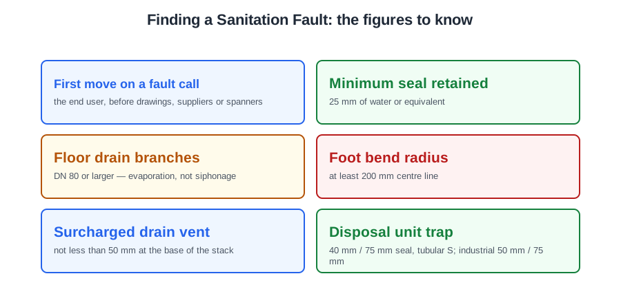
- First move on a fault call
- the end user, before drawings, suppliers or spanners
- Minimum seal retained
- 25 mm of water or equivalent
- Floor drain branches
- DN 80 or larger — evaporation, not siphonage
- Foot bend radius
- at least 200 mm centre line
- Surcharged drain vent
- not less than 50 mm at the base of the stack
- Disposal unit trap
- 40 mm / 75 mm seal, tubular S; industrial 50 mm / 75 mm
- Shower trap distance
- up to 750 mm from the outlet
- Practical gradients
- 18 to 22 mm/m; 9 mm/m only on DN 100/150 at ≥2.5 l/s
- AAV standard
- BS EN 12380; siting from the manufacturer’s instructions
- Lifting plant maintenance
- quarterly commercial, half-yearly multiple dwellings, yearly single
- Disposal unit supply
- fused spur about 10 A, 30 mA RCD, hole 89–90 mm
- Overload sequence
- isolate → remove → clear → reset → refit → test
⚠️ Where people go wrong
- Stripping an appliance before talking to the person who has watched the fault.
- Taking the customer’s account as the conclusion. Where account and evidence disagree, evidence wins.
- Reaching for a British Standard to fault-find a lifting unit. Use the maker’s flow chart.
- Rodding the drain for one slow bath. Strip the trap first.
- Calling a gurgle or a blow a blockage.
- Reading an empty trap as one fault. There are six causes and each leaves its own pattern.
- Missing the pattern that names induced siphonage: fine used alone, empty when the neighbours run.
- Fitting a bottle trap or an interceptor to a disposal unit.
- Oversizing a branch to stop siphonage. It increases deposit accumulation.
- Boxing an AAV into a sealed void, or fitting one in a dusty workshop.
- Expecting an AAV to relieve positive pressure.
- Using a ram gun on a stack with a permanently fixed AAV.
- Reading macerator short cycling as a blockage. It is the non-return valve.
- Capping a lifting plant’s vent. Faecal plants vent above roof level.
- Resetting or de-jamming a disposal unit that is still connected.
- Fitting a disposal unit at the head of a long horizontal run.
📝 10-Question Self-Test
Straight from the Level 3 course question bank. Click an option to see whether you got it right — the explanation appears instantly, and there is nothing to submit.
The person who uses the appliance has watched the fault for weeks and can tell you what happens, which appliances are affected, when it started and whether it only happens when something else is used. That narrows the search before you open anything. Studying the drawings or stripping the appliance down comes after the story, not before it.
A fault-finding flowchart asks a yes or no question and each answer sends you to the next check, so the unit is tested in a safe, logical order for that make and model. BS EN 12056-2 is the tempting pick, but it tells you how the pipework should have been designed — it knows nothing about why this particular pump is failing.
A disposal unit needs a smooth, full bore trap that ground food waste will pass, which is a tubular S trap, 40 mm with a 75 mm seal under Approved Document H Table 1. A resealing bottle trap looks like the careful answer, but BS EN 12056-2 ND.2.3 restricts bottle traps to wash basins, and the restricted bore would soon block.
The non-return valve on the outlet holds the pumped water up in the discharge pipe. If it is defective, that column drains back into the chamber, the level rises past the switch and the unit fires up again, over and over, long after the pan has finished discharging. A float switch set too high would stop the unit starting at all, not make it restart repeatedly.
Slow running means something is holding the flow back, and the trap is the nearest point to the appliance and the likeliest place for hair and soap to gather. It comes apart in minutes. Rodding the main drain starts at the wrong end of the system and proves nothing while every other appliance in the house runs normally.
An interceptor trap belongs in a below ground drain, not on an appliance waste, and BS EN 12056-2 NC.2.6 warns that one close to a stack causes large pressure fluctuations. The other three are above ground appliance traps that suit the job: Table 6 asks for 40 mm with a 75 mm seal on a food waste disposal, and its note allows tubular traps only, not bottle or resealing ones.
Approved Document H paragraph 1.33 says an air admittance valve must not be used in a dust laden atmosphere; on site that means airborne dust, fibres and lint, which clog the air inlet and the sealing face. The valve needs a clean, well ventilated position.
A lifter pumps when its chamber fills; a steady drip from a tap or leaking joint keeps refilling it a little at a time, so the pump cycles repeatedly for almost nothing.
Fault-finding starts with hearing the customer's account and then running the unit to see the fault, following the manufacturer's procedure. Dismantling or ordering parts before the fault has been seen is guesswork.
A countertop basin drops through a hole cut in the worktop, so the maker supplies a template giving the exact cut-out for that bowl. A pedestal basin, a shower tray and a close coupled WC suite all stand on the floor or hang on brackets, so there is nothing to cut out and no template comes with them.
Going further: the lessons behind this article
This article is the public answer. Unit 334 of the Level 3 course takes the same ground to the depth the exam and the synoptic assignment ask for, in 8 lessons:
- Taking the fault call: what the end user can tell you
- Manufacturer data, fault charts and documented history
- Smells and slow running: what each complaint points to
- The six causes of trap seal loss, and how to tell them apart
- Checking traps, branch pipes, gradients and falls
- Air admittance valves: checks when foul air gets in
- WC macerators and lifting plants: the checks that find the fault
- Sink waste disposal units: jams, overloads and blockages
- Sanitation systems: the Unit 334 guide — every article on this unit in one place
- All PlumbMate articles — Level 1, 2 and 3
- The Level 3 course — the whole 8202-35 Diploma