The job is finished, the test kit is in the van, and you are standing in an empty plant room with a torch. Before anything else happens, you walk the system.
The short answer
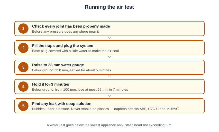
When above ground discharge pipework is commissioned, the first thing to do is check that all joints have been properly made — not fit the test bungs, not discharge everything at once, and not go looking at the drain.
Then the test itself is short: pump gently to 38 mm water gauge, close the inlet cock, let the reading settle, and hold for 3 minutes. Any steady fall is a leak.
And when it fails, locate the leak with soap solution under pressure — never by raising the test pressure.
Walking the system
Start at the highest appliance and work down to the foot of the stack. Working in the direction of flow means you see the pipework the way the water will, and crossflow, wrong falls and back-to-front fittings show up as you go.
- Joints — push-fit fully home to the witness mark, solvent-weld clean and set, ring seals seated, compression tight and not overtightened.
- Open ends — every unused branch, boss and access point capped. An open end fails the air test and lets site rubbish in.
- Support — clips at the manufacturer's spacing, screwed to something solid, no sagging, nothing else hung off the pipework.
- Fall — the designed gradient on every branch. A pipe with no fall holds debris; too steep a fall runs the water away from the solids and can pull seals.
- Direction of fittings — swept entries facing downstream, so a discharge joins the flow instead of hitting the opposite wall.
- Crossflow — no branch discharging into a stack opposite another.
- Access — rodding points and cleaning eyes reachable, and rodding points in stacks above the spillover level.
- Fire stopping made good where pipes pass through walls and floors.
Where the system relies on an air admittance valve, look at it properly. A fully boxed-in AAV needs ventilation openings and an access panel in the boxing. Removing the valve and blanking it, leaving it because the boxing keeps dust off, or drilling a single 6 mm hole and writing it on the report are all wrong.
The visual inspection is a comparison, not an opinion. You are checking the installation against the drawings, the specification and the requirements that apply — Part H for the drainage and waste disposal, Part F for the ventilation of the rooms the appliances sit in (worth noticing, because a sealed, unventilated room is also the wrong place for an AAV).
Anything you cannot resolve goes on a written list with its location. Do not start the air test with outstanding defects and hope they do not matter; they will, and you will have to strip the test down and start again. And record the walk — a list of what was checked, floor by floor, with each defect signed off. It is the first entry on the commissioning record.
Traps and appliances before you test
Half of what a performance test finds could have been found with a tape measure and a look under the basin.
- Wash basin or bidet — 32 mm trap, 75 mm seal.
- Bath or shower — 40 mm trap, 50 mm seal.
- Sink, urinal bowl, disposal unit, washing machine, dishwasher — 40 mm trap, 75 mm seal.
- WC pan, outlet over 80 mm — 100 mm trap, 50 mm seal.
The one that catches people out is the machine waste. A washing machine discharging into unventilated pipework needs a 75 mm seal. The reduced 38 mm seal is allowed only where such an appliance discharges directly to a gully, and 50 mm only on spray tap basins with flush grated wastes and no plug.
Trap type follows the pipework. Where several appliances share a common branch, one trap can lose its seal by induced siphonage while another discharges. The trap that answers that is a resealing trap, which admits a little air and recharges its own seal. A plain bottle trap, P trap or tubular trap on a shared branch has nothing to protect it.
Check the branch lengths against the design at the same time: an unventilated 40 mm branch serving a bath or shower may be at most 3 m; a 32 mm basin branch is limited to 1.7 m. If the pipe on site is longer than the drawing said, the performance test will find it — but you would rather know now.
Then the appliances: every trap fitted directly after the appliance and removable or with a cleaning eye; appliances securely fixed, level and plumb; cistern water levels set to the marked line; pans clearing properly. A wash-down pan is emptied by the force of the flush; a siphonic pan empties itself through a siphon — knowing which you have tells you what a poor clear means.
Give every appliance a trial run. Fill it, let it go, and watch. It should drain speedily, quietly and completely. A basin that empties with a long gurgle, a sink that holds a puddle, a pan that needs two flushes: each of those is a fault in its own right, whatever the performance test says afterwards.
And take particular care with fragile appliances. Fitting a glass wash basin, the point that needs attention is simply that the appliance is not damaged: glass chips under an overtightened waste and a damaged bowl cannot be repaired.
Setting up the air test
A good air test is nine parts preparation. Everything that goes wrong on site — the reading that will not hold, the leak you cannot find, the seal that blows halfway through — usually goes wrong before the pump is squeezed.
Charge the seals first. Run every appliance, or pour water into each trap, until the seal is full. The traps are part of the seal on the system: an empty trap is an open hole and the test will never hold. This is also the moment to note any bowl that empties slowly or noisily — you will meet it again during the performance test.
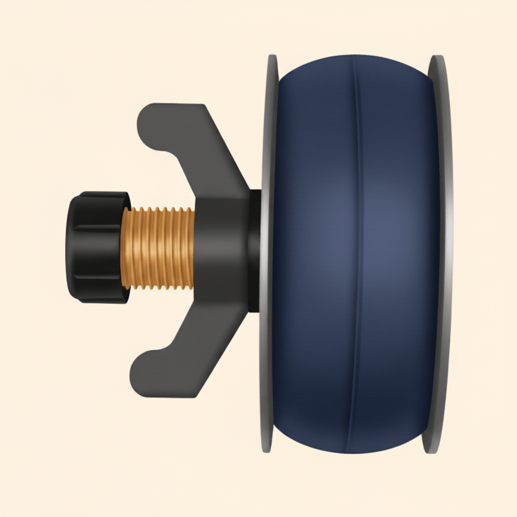
Seal the system. Test plugs or expandable drain bags go into the open ends: the top of the stack or stack vent, the base above the drain connection, and any open branch or access point. On a tall building you may be testing a section, in which case the plugs go at the top and bottom of that section.
To make sure there is a satisfactory air seal at the base of the stack, a small quantity of water, sufficient to cover the plug or bag, can be allowed into the system. That water is not there to recharge the traps, and it is not there to show a falling level. It sits on top of the plug and seals round it, because a mechanical plug on its own can weep air past the rubber.
Connect the gauge, one of two ways:
- A remaining test plug fitted with a tee piece carrying a cock on each branch — one branch to the manometer by flexible tube, air pumped in through the other.
- Or a flexible tube from a tee piece, again with cocks, passed through the water seal of a sanitary appliance. Any water trapped in that tube is removed first.
Fill the manometer with clean water and check it reads zero before you start. On a U gauge the pressure is the difference between the water levels in the two limbs, so a gauge that is not level or not filled to the datum will lie to you all morning.
Prove the pump, the hose and the connections on a short capped length of pipe first; finding out that your own test hose leaks after two hours on a stack is a miserable way to learn the lesson.
One more decision belongs to the preparation: an air admittance valve on the section. A valve is designed to close under positive pressure, so it can normally stay in place — but a valve that is already faulty will bleed the test away and send you hunting a leak that is not there. If a stack with an AAV will not hold pressure and every joint tests clean, take the valve off, cap the connection and test again.
Applying the test
- Check the manometer reads zero.
- Gently squeeze the hand pump until the gauge shows 38 mm water gauge. Pump slowly — a hard squeeze overshoots, and an overshoot can start pushing seals out of shallow traps.
- Close the air inlet cock, so the system is sealed and the gauge is reading the pipework, not the pump.
- Let the reading settle, then start timing.
- Wait 3 minutes and read again. No pressure drop, the system is sound. A drop means find the leak, rectify it and retest.
Why the reading settles before you time it: air warms slightly as it is compressed and then cools back towards the temperature of the pipework, which can move the column in the first seconds. Let it steady, note the figure you are holding, and time from there. A steady fall over the three minutes is a leak, however small.
The air test should normally be completed in one operation, but for large multi-storey systems, testing in sections may be necessary — and section testing is also what you do when part of the work is about to be closed up. Where you test in sections, record which section each result belongs to, or the record is useless.
Things that make a sound system look unsound: a trap that was not fully charged, or one siphoned by your own pumping; a plug or bag that has slipped, or a base plug without its film of water; a leaking test hose, cock or pump; an open end nobody capped, usually a boss in a duct; and an AAV left in circuit.
And the thing that makes an unsound system look sound: stopping the clock early. Three minutes is not two. Watch the gauge for the whole period rather than walking away. A reading that falls quickly and then steadies usually means a seal or plug has moved and re-seated; a reading that creeps down evenly for the whole period is a genuine leak. The shape of the fall tells you where to start looking.
Record the result as you take it, not from memory back at the van. Section, pressure, time held, whether the reading moved — and if it failed, what you found and the result of the retest. A record showing only passes tells the next person nothing about where the weak points were.
Locating a leak
Soap solution is the method for plastics. With the pipework under internal pressure, a soap solution or proprietary leak detection fluid is applied to the pipes and joints, and leakage is shown by the formation of bubbles. Cheap, harmless to every pipe material, and it puts your finger on the exact joint.
The routine: repressurise, brush the fluid onto each joint in turn working up the stack, and watch. Rectify, wipe the fluid off, and retest.
A smoke producing machine can introduce smoke under pressure, and leakage is seen as it escapes. But the hard rule is that smoke testing of plastics pipework should be avoided, because naphtha has a detrimental effect, particularly on ABS, PVC-U and MUPVC, and rubber jointing components can also be affected. Igniting a cartridge at the rodding eye of a plastics stack is the wrong answer twice over.
Work methodically rather than by instinct. Start at the joint nearest your test connection and work outwards, marking each joint you have proved with a chalk cross. On a tall stack that discipline is what stops you brushing the same six joints three times while the real leak sits in the duct behind you. And wipe the solution off afterwards — left on the pipe it attracts dust.
What not to do:
- Do not raise the test pressure to force the leak to show. It blows trap seals, can displace joints and proves nothing.
- Do not fill the whole stack with water. A whole-system water test puts a head on the pipework it was never designed for.
- Do not drain the system and let joints dry out and try again. The joint that leaked will leak again.
- Do not replace every solvent-weld joint on the run. You are guessing, and you will introduce new faults.
- Do not hide a weeping joint with silicone.
Afterwards, rectify properly, make good anything opened up, and repeat the test on the same section. Record both the failure and the pass — the record is the honest history of the installation.
Water tests and gutters
There is no justification for a water test to be applied to the whole of the plumbing system. Sanitary pipework is designed to run part full at atmospheric pressure; fill a stack to the top-floor spillover level and every joint on the ground floor is carrying a head it was never built for.
Where a water test does apply is the pipework below the lowest sanitary appliance — the section that will actually hold water if the drain backs up. That part may be tested by inserting a test plug in the lower end, filling to the flood level of the lowest sanitary appliance, provided the static head does not exceed 6 m. The 6 m figure is the one to remember; it is not 1.5 m.
Rainwater work gets tested with water, because that is what it carries. The way to test a gutter and downpipe for both soundness and performance is to pour water into the gutter and inspect for ponding and leaks. One operation answers two questions: does it leak, and does it drain to the outlet the way it was set out?
The formal method for gutters over walls and internal areas:
- Plug the gutter outlets.
- Fill the gutter to the overflow level, or to the lower level of the freeboard.
- Check visually for leaks after 5 minutes.
- If leaks are found, reseal and repeat the test.
Sighting along the gutter with a spirit level tells you it has a fall, but nothing about joints. Checking the brackets are tight and assuming it is sound is not a test at all. And a rainwater downpipe is not pressure tested at 1.5 bar — it is an open gravity pipe.
Ponding matters as much as leaking. Water standing in a low spot means the gutter has not been fixed to even falls, and standing water collects silt, freezes and overloads the brackets.
One caution when you inspect: joints in external vertical rainwater pipes less than 75 mm diameter are not normally sealed, so a little water running down the outside of such a joint is not automatically a defect. A joint that sprays, a gutter that overflows or a run that ponds is.
🔢 The numbers worth memorising
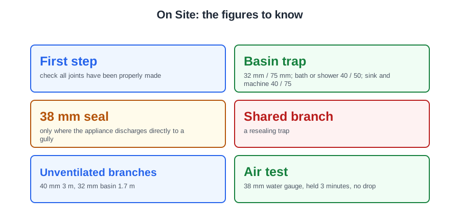
- First step
- check all joints have been properly made
- Basin trap
- 32 mm / 75 mm; bath or shower 40 / 50; sink and machine 40 / 75
- 38 mm seal
- only where the appliance discharges directly to a gully
- Shared branch
- a resealing trap
- Unventilated branches
- 40 mm 3 m, 32 mm basin 1.7 m
- Air test
- 38 mm water gauge, held 3 minutes, no drop
- Base plug
- covered with a small quantity of water for the air seal
- Leak location
- soap solution under pressure, bubbles
- Smoke on plastics
- avoided — naphtha attacks ABS, PVC-U and MUPVC
- Water test
- below the lowest appliance only, static head not exceeding 6 m
- Gutter test
- plug the outlets, fill, check after 5 minutes for ponding and leaks
- External rainwater joints
- under 75 mm are not normally sealed
⚠️ Where people go wrong
- Fitting the test bungs before anybody has walked the system.
- Starting an air test with defects still outstanding.
- Blanking a boxed-in AAV, or drilling one small hole and writing it up.
- Fitting a 50 mm seal to a washing machine waste on unventilated pipework.
- Fitting a plain trap on a branch shared by several appliances.
- Testing with traps that were never charged.
- Forgetting the film of water over the base plug.
- Starting without checking the manometer reads zero, or without proving your own kit.
- Pumping hard to 38 mm. An overshoot pushes seals out.
- Timing from the moment you close the cock, before the reading settles.
- Stopping the clock at two minutes.
- Testing in sections without recording which section each result belongs to.
- Raising the pressure to find a leak, or draining and drying the joints.
- Smoke testing a plastics stack.
- Replacing every solvent-weld joint on a run to be sure.
- Water testing a whole system, or quoting 1.5 m instead of 6 m.
- Calling a spirit level along a gutter a test.
📝 10-Question Self-Test
Straight from the Level 3 course question bank. Click an option to see whether you got it right — the explanation appears instantly, and there is nothing to submit.
Commissioning starts with the visual inspection, walked in the direction of flow, and checking that every joint has been properly made is the first item on it. There is no sense plugging up and pumping a system that has an obvious defect in it. Fitting the test bungs and connecting the manometer comes next, once the walk round is clear.
Sanitary pipework carries no structural load, so it has to be clipped at the manufacturer’s spacing to something solid, with no sagging in near-horizontal runs. A sag holds water and debris and becomes a blockage, so support is a standard item on the visual inspection. Expecting every run to be level is wrong: discharge pipes need a fall.
The air test puts the system under 38 mm water gauge, read on a U gauge manometer, and it must hold that pressure with no drop for at least three minutes. Approved Document H paragraph 1.38 and BS EN 12056-2 NG.3.1.2 both give it. It is deliberately a very low pressure: much more and you start pushing trap seals out of shallow traps.
BS EN 12056-2 NG.3.1.3 gives soap solution or a proprietary leak detection fluid brushed onto the pipes and joints while the system is under pressure — bubbles put your finger on the exact joint. Retesting at twice the pressure tempts, but it blows trap seals, can displace joints and proves nothing. Draining down and letting joints dry changes nothing; the joint that leaked will leak again.
Above ground discharge pipework is proved sound by an air test: plug the open ends, charge the traps, pump to 38 mm water gauge and hold it for three minutes with no drop. A soap solution is used afterwards to find where a failed test is leaking, so it locates the fault rather than establishing soundness. Dye tracing and CCTV are below ground drainage tools.
BS EN 12056-2 National Annex NG sets out the air test and performance tests for sanitary pipework, and Approved Document H points to it as the alternative approach.
An air admittance valve must be in a ventilated space and accessible for maintenance. Boxing it in defeats both, so the boxing needs vents for air and an access panel.
BS 8000-13 2.1.2.2 says wrappings and protection on sanitary appliances are left in place for as long as possible, so the tape comes off at the end, once the system has been tested and is being handed over, not as soon as the water is on.
With the system under air test, leak detection fluid brushed on the joints bubbles where air escapes: BS 8000-13 clause 4.1.1 gives soap solution applied to suspect areas for exactly this. A water test is allowed, but only at the lowest level of the pipework, so it will not find a leak higher up; raising the pressure blows trap seals, and discharging appliances tests performance, not soundness.
The air test is a positive pressure of at least 38 mm water gauge held for at least 3 minutes.
Going further: the lessons behind this article
This article is the public answer. Unit 334 of the Level 3 course takes the same ground to the depth the exam and the synoptic assignment ask for, in 6 lessons:
- Walking the finished system: the visual inspection on site
- Traps, seals and appliances: the checks before you test
- Setting up the air test: plugs, manometer and charged traps
- Applying the air test and reading the result
- Locating a leak after a failed air test
- The water test and the gutter test: where each one applies
- Sanitation systems: the Unit 334 guide — every article on this unit in one place
- All PlumbMate articles — Level 1, 2 and 3
- The Level 3 course — the whole 8202-35 Diploma