A site agent points at your drawing and asks two questions. Who says the kitchen sink waste has to be 40 mm, and where does all this water end up?
The short answer
Both answers come out of a short list of documents. Requirement H1 of the Building Regulations is the law (in Northern Ireland, Part N); Approved Document H is the guidance that shows how to satisfy it; and BS EN 12056 is the code of practice, not the law.
Everything else follows from two ideas: every trap must retain at least 25 mm of water seal under working and test conditions, and an unventilated branch has a maximum length that gets shorter as the gradient gets steeper.
The documents, and where the water goes
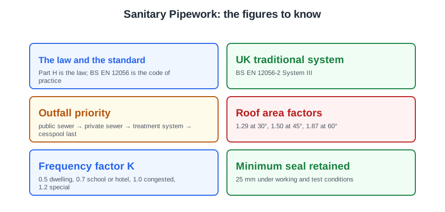
H1 says an adequate system of drainage shall carry foul water from appliances within the building to a proper outfall. Section H1 is foul water drainage, H2 wastewater treatment and cesspools, H3 rainwater drainage.
BS EN 12056 comes in five parts: general and performance, sanitary pipework (Part 2 — the system types and the calculations), roof drainage, wastewater lifting plants, and installation, testing and maintenance. Approved Document H names it as an alternative way of meeting H1, and records that System III is the type traditionally used in the UK.
Foul water means waste from a sanitary convenience or bidet, waste from an appliance used for washing foul receptacles, and water used for food preparation, cooking or washing. H1 sets the outfall in order of priority: a public sewer first; then a private sewer connecting to one; then a septic tank with secondary treatment; and only where none of those is practicable, a cesspool.
Below ground, three arrangements: a combined system carries foul and surface water in one shared sewer; a separate system keeps them apart, the surface water discharged without any treatment to a watercourse or soakaway; a partially separate system takes most surface water separately but allows a little into the foul drain.
Surface water is sized on area, not appliances. A pitched roof becomes an effective design area by multiplying the plan area by 1.29 at 30°, 1.50 at 45° and 1.87 at 60°. A roof 8 m long measuring 4 m in plan at 45° gives 32 m², and 32 × 1.50 = 48 m².
| Appliance | Waste or branch size |
|---|---|
| Wash basin, bidet | 32 mm |
| Bath, shower, sink, washing machine, dishwasher, urinal bowl | 40 mm |
| Food waste disposal unit, branch serving two to four basins | 50 mm |
| WC with outlet under 80 mm | 75 mm |
| WC with outlet over 80 mm | 100 mm |
Those are nominal sizes: a pipe called 40 mm measures about 42 mm outside and a 100 mm soil pipe about 110 mm, which is why a bath waste is written 40/42 mm and a WC branch 100/110 mm.
A house with one WC never needs calculating; a block of flats does. Above-ground pipes are sized on discharge units (DU): add the discharge units of everything the pipe serves, then Qww = K √∑DU, where K is the frequency factor — 0.5 for a dwelling or office, 0.7 for a school or hotel, 1.0 for congested public use, 1.2 for special use. Do not confuse discharge units with loading units, which size cold water supply pipes.
Traps and seals
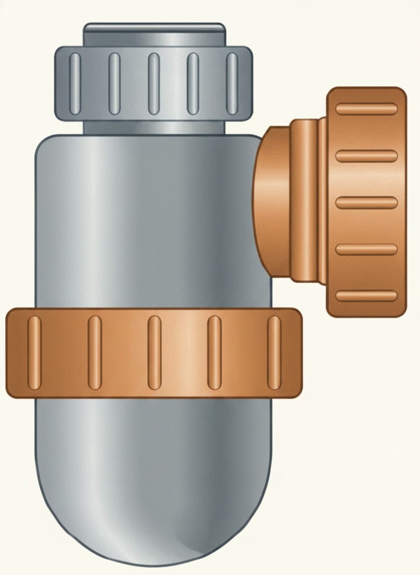
A tenant complains of a drain smell that comes and goes. You put a dip stick in the basin trap and it reads 20 mm where it should read 75.
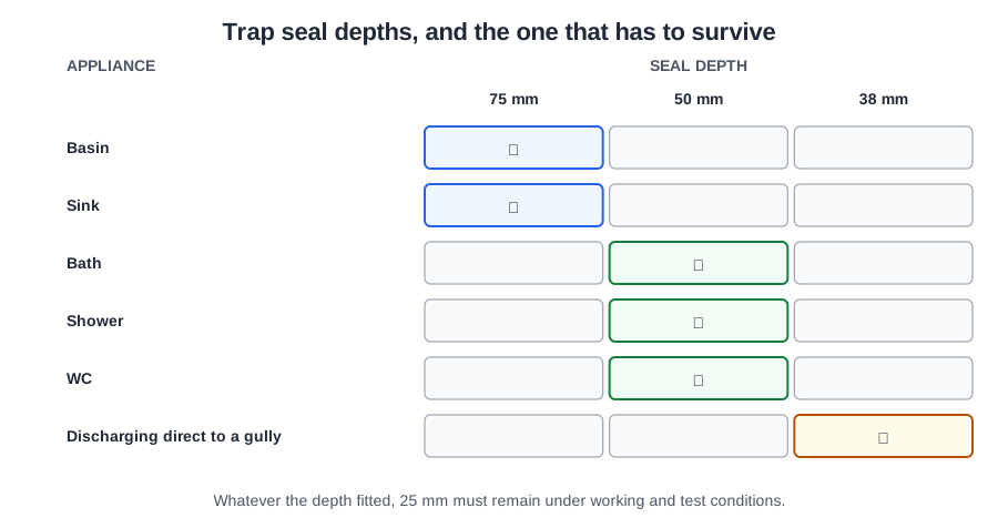
Every point of discharge must have a trap so foul air cannot enter the building, and under working and test conditions every trap must retain at least 25 mm of water seal. That 25 mm is the pass mark; the seal it starts with is deeper.
| Appliance | Trap diameter | Seal depth |
|---|---|---|
| Wash basin, bidet | 32 mm | 75 mm |
| Bath, shower | 40 mm | 50 mm |
| Sink, urinal bowl, food waste disposal unit, washing machine, dishwasher | 40 mm | 75 mm |
| WC pan, outlet under 80 mm | 75 mm | 50 mm |
| WC pan, outlet over 80 mm | 100 mm | 50 mm |
Two relaxations. A basin seal may drop to 50 mm only on a spray tap basin with a flush grated waste and no plug. And where a bath, shower or flat-bottomed appliance discharges directly to a gully, the seal may be reduced to not less than 38 mm.
The four ways a seal goes
- Self-siphonage happens to the appliance that is discharging. A small bore pipe runs full, a plug of water forms, and the partial vacuum behind it drags the seal out after the flow. Basins suffer most, because they empty fast into a 32 mm pipe.
- Induced siphonage empties a trap that is not in use: another appliance on the same branch, or on the stack above, runs full bore and the suction pulls a passive seal out.
- Back pressure, or compression, is the opposite. Water falling down a stack pushes air ahead of it, and at a sharp bend at the base, or above an offset, the pressure turns positive and blows foul air and water back through the seal.
- Evaporation is the slow one: a floor gully or an unused bathroom simply dries out.
What makes self-siphonage worse: a funnel shaped appliance, the length, gradient and diameter of the branch, the type of trap and the grid at the outlet, an overflow connected into the trap, sharp bends, and whether the branch is vented.
P traps are the default on a primary ventilated system, with the branch the same diameter as the trap. Bottle traps should only be used on wash basins. Resealing and anti-vacuum traps are made for unventilated small bore branches; they need regular inspection and can be noisy, so they are a remedy, not a first choice.
Access matters as much as the seal. If the trap is part of the appliance, the appliance must be removable; every other trap must be fitted directly after the appliance and be removable or fitted with a cleaning eye. Where a waste pipe runs to a gully at ground level it must finish through the grating but above the water level of the trap seal — never below the water and never onto the top of the grating.
The branch limits
In a primary ventilated stack system, all the appliances are closely grouped around the discharge stack, and the stack itself does the ventilating. There are no separate ventilating pipes, which is why the pipe is called a soil and vent pipe. Previously the single stack system, and the arrangement behind BS EN 12056-2 System III.
It only works if the pipework is disciplined: appliances close to the stack; P traps with the branch the same diameter as the trap; bends and junctions avoided where possible and made with a large radius where they cannot be; and the stack run straight with a large radius bend at the base.
| Branch | Diameter | Maximum length | Gradient |
|---|---|---|---|
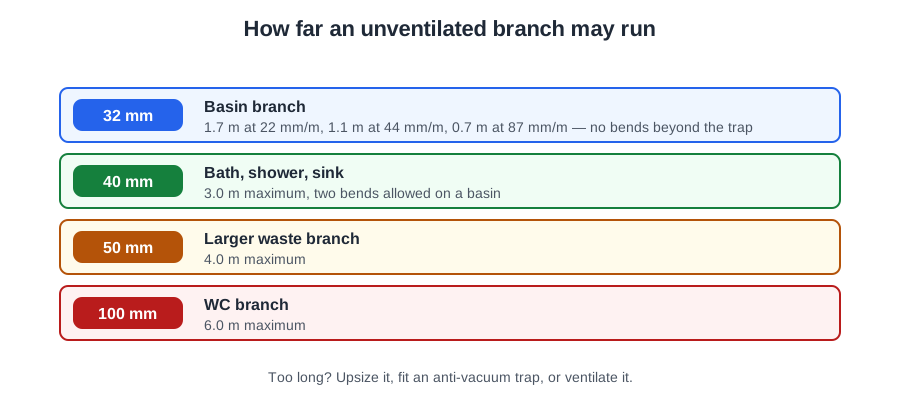
| Wash basin or bidet | 32 mm | 1.7 m | 18 to 22 mm/m |
| Wash basin or bidet | 32 mm | 1.1 m | 18 to 44 mm/m |
| Wash basin or bidet | 32 mm | 0.7 m | 18 to 87 mm/m |
| Basin, bath, shower, sink, washing machine | 40 mm | 3.0 m | 18 to 44 mm/m |
| Two to four basins, urinals | 50 mm | 4.0 m | 18 to 44 mm/m |
| WC, outlet over 80 mm | 100 mm | 6.0 m | 18 mm/m or more |
The figure to give for an unventilated 100 mm WC branch is 6 m, laid at 18 mm/m (about 1 in 55) or steeper. (Approved Document H Table 2 now allows an unventilated 100 mm branch serving up to eight WCs to run 15 m; the 6 m figure comes from the earlier code of practice and remains the one to give.)
Notice what the basin rows are telling you. Steepen the gradient and the permitted length falls, because a steeper pipe runs full more readily and siphons the trap: 32 mm at 22 mm/m may run 1.7 m; at 44 mm/m only 1.1 m; at 87 mm/m only 0.7 m.
So for a basin at 2.6 m from the stack, the first option is not a vent and not a special trap: it is to increase the diameter. Take the branch to 40 mm and 3 m is allowed. Flattening it below 18 mm/m is not the answer, because the pipe stops being self-cleansing.
And where a horizontal 40 mm waste sags between two clips, it holds water in the dip, loses its fall and stops being self-cleansing. The remedy is to re-clip the pipe at the correct centres — for plastics: 32 to 40 mm, 0.5 m horizontal and 1.2 m vertical; 50 mm, 0.6 m and 1.2 m; 75 to 100 mm, 0.9 m and 1.8 m.
Cross-flow and the no connection zone
A first floor bath fills with dirty water whenever the WC on the opposite side of the stack is flushed. Nothing is blocked — the two branches have been connected opposite one another.
The rule is short: a branch pipe should not discharge into a stack in a way which could cause cross-flow into any other branch pipe. BS EN 12056-2 turns that into geometry: the smaller branch should be connected at or above the centre line of the larger connection, or at right angles or less to it, or at least 200 mm below it.
Every branch creates a no connection zone on the opposite side of the stack, and no other branch may have its centre line inside that zone (a centre line may sit exactly on the boundary). The zone gets taller as the stack gets bigger: 90 mm on a 75 mm stack, 110 mm on 100 mm, 210 mm on 125 mm and 250 mm on 150 mm, together with a 200 mm dimension that does not change with stack diameter.
Making the connection itself:
- Junctions between branches of about the same size are swept in the direction of flow with a 25 mm minimum radius, or made at 45°.
- A branch of 75 mm or more joining a stack of the same diameter is swept with a radius of at least 50 mm, or connected at 45°. Branches entering at 45° or less need no swept inlet.
- Branches up to 40 mm joining a horizontal branch of 100 mm or more connect to the upper part of the pipe wall, so the larger flow cannot back up them.
- On a 32 mm basin branch, any change of gradient near the stack must be within 250 mm of it.
A near horizontal entry with a tight radius is the worst case for another reason: it produces the greatest suction below the branch inlet, and suction below an inlet is what empties the traps underneath it.
Boiler condensate may be connected to sanitary pipework: at least 22 mm pipe through a 75 mm condensate trap, preferably into an internal stack, and where it goes into a branch, downstream of any sink waste connection. The pipework must resist a pH of 6.5 and lower.
Ventilated branches and secondary ventilated stacks
An architect has put a WC 8 m from the stack. Once a branch passes its unventilated limit there are only three legitimate answers: a branch ventilating pipe to external air, a branch ventilating pipe to a ventilating stack, or an air admittance valve.
So for that WC at 8 m, the acceptable arrangement is a ventilated branch. A stub stack is no help — it is limited by height above the drain invert, not by branch length. A combined system is a below ground arrangement and has nothing to do with a branch at all.
A branch ventilating pipe is:
- Connected to the branch within 750 mm of the trap, and as close as practicable.
- Given a continuous incline up to where it connects, so condensation cannot form a water lock.
- Connected to the ventilating stack or stack vent above the highest spill-over level of the appliances served.
- 25 mm minimum for a single appliance, or 32 mm where the branch is longer than 15 m or has more than five bends.
- Where it runs straight to open air, finishing at least 900 mm above any opening into the building within 3 m.
Read the three system names as a sequence and they stop blurring:
- Primary ventilated — appliances close, stack vents everything.
- Secondary ventilated — appliances still close, but the stack gets a second stack to help it against the pressure swings of a tall or heavily loaded building.
- Ventilated branch — appliances far apart, every trap gets its own vent.
On a secondary ventilated system the cross-connections slope upwards from the discharge stack, at up to 67.5°, so water cannot get into the vent. The lower end connects below the lowest branch connection and above the bend at the base; the upper end joins the stack vent or passes through the roof. A ventilating stack serving dwellings up to 10 storeys is at least 32 mm; on a ventilated branch system, where the stack only collects branch vents, 30 mm is usually enough.
The stack itself
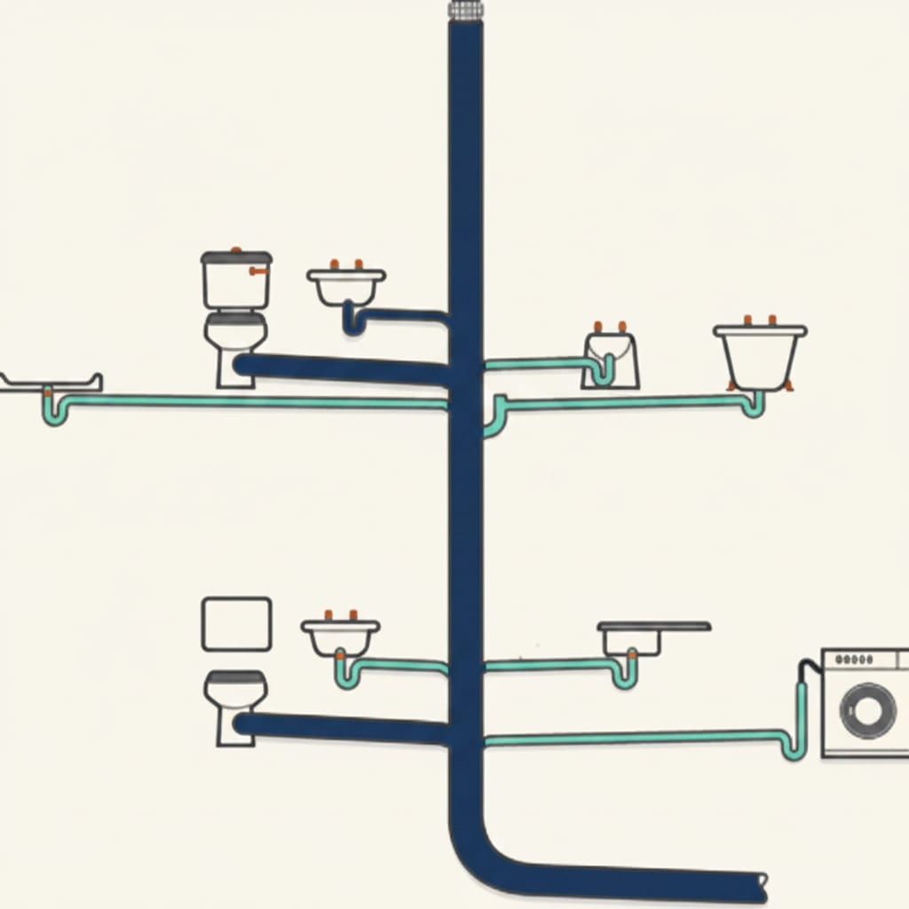
| Stack size | Maximum capacity |
|---|---|
| 50 mm (no WCs) | 1.2 l/s |
| 65 mm (no WCs) | 2.1 l/s |
| 75 mm (max one small outlet WC) | 3.4 l/s |
| 90 mm | 5.3 l/s |
| 100 mm | 7.2 l/s |
A stack serving urinals is at least 50 mm; serving WCs with outlets under 80 mm at least 75 mm; over 80 mm at least 100 mm. The internal diameter is never less than the largest trap or branch connected to it, and it must not reduce in the direction of flow. The dry stack vent above the highest branch may be reduced in one and two storey houses but not below 75 mm.
The bend at the foot is where back pressure is made. Give it as large a radius as possible and at least 200 mm at the centre line, or use two 45° bends. Then keep branches away from it:
- 450 mm minimum from the invert of the tail of the bend to the lowest branch, in single dwellings up to three storeys.
- 750 mm in multi-storey buildings up to five storeys.
- Over five storeys, ground floor appliances get their own stack or go direct to a drain or gully; over 20 storeys, first floor appliances as well.
A ground floor WC may drop straight into the drain instead, but only where the depth from floor level to the drain is 1.3 m or less.
An offset in the wet part of a stack makes pressure trouble on both sides: suction below it and positive pressure above. Avoid them. Where unavoidable in a building of not more than three storeys, allow no branch connection within 750 mm of the offset. Over three storeys a ventilating stack may be needed, cross-connected above and below. An offset above the topmost branch does not need venting.
A stub stack is a short stack, closed at the top with an access fitting or AAV, taking ground floor appliances into the drain. It is allowed only where it connects into a ventilated discharge stack or a ventilated drain not subject to surcharge, and where no connected WC has a floor level more than 1.3 m above the invert of the drain connection, and no other branch has its centre line more than 2 m above that invert. It is also one honest answer for a customer who wants an extra ground floor WC that cannot reach the existing stack.
Air admittance valves and terminations
A developer building 19 houses wants an AAV in every loft, so no stack goes through a roof. That is allowed, but not on its own.
An air admittance valve is a one-way valve to BS EN 12380. Negative pressure lifts a diaphragm and lets air in; when the pressure equalises the diaphragm drops back, so foul air cannot get out. That lets a ventilated discharge stack terminate inside the building.
The advantages sell themselves to a builder: less pipework, no roof penetration and so no route for water ingress, no foul smells indoors, and more freedom in the design.
Where it may and may not go:
- Above the flood level of the highest appliance it serves, so a blockage cannot back foul water up to the valve.
- In a space with adequate ventilation, accessible for maintenance, and removable so the stack can be rodded.
- Never outside the building, and never in a dust laden atmosphere.
Neither Approved Document H nor BS EN 12056-2 sets a height for an AAV. The often quoted 1 m above the spill-over level is a manufacturer's rule of thumb, not a rule from a standard.
And there are places an AAV must not be relied on: it must not reduce the ventilation the below ground system needs; it should not be used where the drain has an interceptor trap or is subject to surcharge, because both need an open pipe to relieve positive pressure; and it must not be the only ventilation on a system serving a septic tank or cesspool.
So, the 19 houses. The below ground system must be ventilated by a flow of air — a ventilating pipe at or near the head of each main drain, and an open ventilating pipe, with no AAV on it, on any drain fitted with an intercepting trap or subject to surcharge. (You may still hear "one open stack in five", or open pipes at the head and midpoint for 11 to 20 dwellings. Those came from the withdrawn BS 5572; BS EN 12056-2 contains no dwelling count. Give the Approved Document rule.)
Where the stack does go to open air it finishes at least 900 mm above any opening into the building within 3 m, with a wire cage or perforated cover that does not restrict air flow — metallic in rodent control areas. Two consequences: a vent pipe finishing level with an openable window is acceptable only if it is at least 3 m away horizontally; and where it stays within 3 m, 900 mm above the opening is the least height it may terminate at.
🔢 The numbers worth memorising
- The law and the standard
- Part H is the law; BS EN 12056 is the code of practice
- UK traditional system
- BS EN 12056-2 System III
- Outfall priority
- public sewer → private sewer → treatment system → cesspool last
- Roof area factors
- 1.29 at 30°, 1.50 at 45°, 1.87 at 60°
- Frequency factor K
- 0.5 dwelling, 0.7 school or hotel, 1.0 congested, 1.2 special
- Minimum seal retained
- 25 mm under working and test conditions
- Seal depths
- basin and sink 75 mm; bath, shower and WC 50 mm
- Direct to a gully
- seal may reduce to 38 mm
- 32 mm basin branch
- 1.7 m at 22 mm/m, 1.1 m at 44, 0.7 m at 87
- 40 mm branch
- 3.0 m; 50 mm 4.0 m; 100 mm WC 6.0 m
- Plastics clip spacing
- 32–40 mm 0.5 m / 1.2 m; 50 mm 0.6 / 1.2; 75–100 mm 0.9 / 1.8
- Cross-flow rule
- at or above the centre line, at right angles or less, or 200 mm below
- No connection zone height
- 90 / 110 / 210 / 250 mm on 75 / 100 / 125 / 150 mm stacks
- Branch vent
- within 750 mm of the trap, 25 mm (32 mm over 15 m or five bends)
- 100 mm stack
- 7.2 l/s; stack vent never below 75 mm
- Base bend
- at least 200 mm radius at the centre line
- Lowest branch above the invert
- 450 mm to three storeys, 750 mm to five
- Stub stack
- WC 1.3 m, other branches 2 m above the invert
- AAV
- BS EN 12380, above the flood level, ventilated space, never outside
- Open termination
- 900 mm above any opening within 3 m
⚠️ Where people go wrong
- Calling BS EN 12056 the law. Part H is the law; the standard is guidance.
- Confusing discharge units with loading units, which size cold water supply.
- Working a pitched roof on its plan area without the slope factor.
- Treating 25 mm as the seal a trap starts with. It is the minimum retained.
- Fitting a bottle trap anywhere but a wash basin.
- Running a waste pipe below the water level of a gully trap, or onto the grating.
- Assuming a steeper branch may run further. The permitted length falls.
- Reaching for a vent when a bigger branch would do.
- Flattening a branch below 18 mm/m. It stops being self-cleansing.
- Connecting a bath branch straight opposite a WC branch.
- Reducing a stack in the direction of flow, or a stack vent below 75 mm.
- Bringing a branch in too close to the base bend.
- Treating a stub stack as an answer to a long branch. Its limits are heights above the invert.
- Fitting an AAV outside, below the flood level, or in a dusty loft.
- Quoting a 1 m height for an AAV. No standard sets one.
- Relying on AAVs alone across a site. The drain still needs an open vent at its head.
📝 10-Question Self-Test
Straight from the Level 3 course question bank. Click an option to see whether you got it right — the explanation appears instantly, and there is nothing to submit.
Above-ground discharge pipes are sized by adding the discharge units of the appliances they serve and reading the pipe size from the tables; discharge units are the design load figure in BS EN 12056-2.
Approved Document H 2.18 requires the drainage system to be ventilated by a flow of air: a ventilating pipe at or near the head of each main drain, and an open ventilating pipe (no air admittance valve) on any drain fitted with an intercepting trap or subject to surcharge. Paragraph 1.33 adds that air admittance valves must not reduce that below-ground ventilation. The old rules of one open stack in five and "head and midpoint for 11 to 20 dwellings" came from BS 5572, withdrawn and replaced by BS EN 12056-2, which has no dwelling count.
A vent pipe open to outside air has to finish at least 900 mm above any opening into the building that is within 3 m of it, so a pipe stopping level with a window only complies by being outside that 3 m radius. Approved Document H paragraph 1.31. 0.9 m is the height above an opening, not the distance away from it.
Approved Document H paragraph 1.9 allows a ground floor WC branch to discharge directly to the drain only where the depth from floor level to the drain is 1.3 m or less, so that is as far below the floor as the connection may go. Any deeper and the vertical drop drags air down with the water and the trap seals suffer. 1.8 m is well past the limit.
The termination rule is 900 mm above any opening into the building within 3 m of the pipe, so a stack finishing level with an openable window rather than above it has to clear that 3 m zone horizontally. Approved Document H paragraph 1.31. 2.5 m is still inside the zone, so the 900 mm height requirement would still bite.
Approved Document H Table 2 allows an unventilated 100 mm branch serving up to eight WCs to run 15 m at a fall of 18 to 90 mm per metre, and BS EN 12056-2 Table 6 gives the same 15 m for a group of up to eight WCs and no limit at all for a single one. A 75 mm branch to a single WC is also allowed 15 m. The familiar 6 m is trade and textbook practice, carried in the City and Guilds branch length table and originally from the withdrawn BS 5572. It is a sensible working maximum, but it is not the limit either current document sets.
Table 2 allows an unventilated 100 mm branch serving up to eight WCs to run 15 m at a fall of 18 to 90 mm per metre, so at 8 m the branch may discharge to a primary ventilated stack with no branch ventilating pipe at all. The 6 m working figure is trade and textbook practice from the withdrawn BS 5572, not a limit in the Approved Document. A stub stack is limited by height above the drain invert rather than by branch length, and a combined system is a below ground arrangement, nothing to do with a branch. Where a branch ventilating pipe is used, paragraph 1.22 puts its connection within 750 mm of the trap.
A drain fitted with an intercepting trap is sealed from the sewer, so the only relief for positive pressure is an open ventilating pipe. An air admittance valve lets air in and never out, which would leave that drain unrelieved; Approved Document H paragraph 1.29 calls for an open pipe of at least 50 mm at the base of such a stack. A rest bend sits at the foot of every stack and rules nothing out.
Approved Document H 1.30 allows a stub stack where no branch other than a WC has its centre line more than 2 m above the invert of the connection or drain, and no connected WC has a floor level more than 1.3 m above it. Go higher than 2 m and the stack has to be ventilated. The 1.3 m figure is the WC limit, not the waste one, which is the swap most people make.
Approved Document H paragraph 1.13 says a branch discharging to a gully terminates between the grating or sealing plate and the top of the water seal. Below the grating it cannot splash out of the gully, and above the seal it cannot be air locked or silted up by standing water. Taking the pipe below the water level looks tidier but drowns the outlet and encourages the branch to siphon.
Going further: the lessons behind this article
This article is the public answer. Unit 334 of the Level 3 course takes the same ground to the depth the exam and the synoptic assignment ask for, in 7 lessons:
- Sanitary pipework: the rules and the standard sizes
- Traps, seal depths and how a trap loses its seal
- Primary ventilated stacks: the branch limits that decide the layout
- Joining branches to the stack: cross-flow and the no connection zone
- Ventilated branches and secondary ventilated stack systems
- Discharge stacks: sizes, the base, offsets and stub stacks
- Air admittance valves, stack terminations and housing sites
- Sanitation systems: the Unit 334 guide — every article on this unit in one place
- All PlumbMate articles — Level 1, 2 and 3
- The Level 3 course — the whole 8202-35 Diploma