A customer wants the guttering replaced on a rear extension. You measure the roof: 8 m along the eaves, 3 m to the ridge on plan, pitched at 30°. That is 24 m² on the tape measure. It is not 24 m² of catchment.
The short answer
Rain does not fall straight down. Wind drives it at an angle, so a pitched roof presents more surface to the rain than its plan area suggests — and a wall standing above a roof sheds its own water onto that roof.
The figure a gutter is sized for is the effective roof area: the plan area corrected for pitch, with any contributing wall added. That is why an online calculator asks for the angle of the roof as well as its size.
And there are two accepted methods — Approved Document H Table 1, or BS EN 12056-3. Never a rafter-length method, and never both multiplied together. Pick one, state which one you used, and stay with it.
The two methods
Method 1 — Approved Document H Table 1. Multiply the plan area by a factor for the pitch.
| Type of surface | Effective design area |
|---|---|
| Flat roof | Plan area of the relevant portion |
| Pitched roof at 30° | Plan area × 1.29 |
| Pitched roof at 45° | Plan area × 1.50 |
| Pitched roof at 60° | Plan area × 1.87 |
| Pitched roof over 70°, or any wall | Elevational area × 0.5 |
Method 2 — BS EN 12056-3. The UK National Annex assumes rain is wind driven at 26° to the vertical, that is 2 in 1, so:
A = LR × (BR + HR ÷ 2)
where LR is the length of roof to be drained, BR the plan width from gutter to ridge, and HR the height from gutter to ridge. In plain terms: a sloping roof collects its plan area plus half its elevation area. Each gutter is designed for the wind direction that gives it the maximum flow.
Two worked examples
A sloping roof 10 m long, plan width 6 m, rise 4 m:
A = 10 × (6 + 4 ÷ 2) = 10 × 8 = 80 m²
The extension, with a wall above it. 8 m along the eaves, 3 m plan width, pitched at 30°, with the house wall rising 2.5 m for the same 8 m:
- Plan area of roof = 8 × 3 = 24 m²
- Pitch factor 1.29, so roof effective area = 31 m²
- Wall elevational area = 8 × 2.5 = 20 m²; contribution = 20 × 0.5 = 10 m²
- Total effective area = 41 m²
Nearly double the tape measure figure.
BS EN 12056-3 adds one limit to the wall rule: a single wall contributes 50 per cent of its area up to a maximum exposed height of 10 m. Where two walls form an angle or a bay, assume the wind direction presenting the greatest vertical area.
And not every roof needs a gutter: gutters and rainwater pipes may be omitted from a roof of not more than 6 m², at any height, provided no other area drains onto it. That is the reason for the blank row at the top of the gutter table. A complex roof is dealt with by calculating each portion separately and adding the results.
Sizing the gutter
BS EN 12056-3 puts the flow into one equation:
Q = r × A × C
where r is the rainfall intensity in l/s per m², A the effective roof area, and C a runoff coefficient taken as 1.0. Rainfall intensity is a local figure; a return period of one year is the minimum for eaves gutters and flat roofs, and for underground surface water drainage Approved Document H uses a design intensity of 0.014 l/s per m². Where no statistical data exists, minimum intensities run from 0.010 to 0.060 l/s per m², multiplied by a risk factor:
| Situation | Risk factor |
|---|---|
| Eaves gutters | 1.0 |
| Eaves gutters where overflowing would cause particular inconvenience | 1.5 |
| Non-eaves gutters, and where heavy rain or a blockage could spill into the building | 2.0 |
| Where exceptional protection is needed, e.g. an operating theatre | 3.0 |
For ordinary domestic eaves gutters you do not have to work Q out by hand. Approved Document H3 Table 2 lists the largest effective roof area that may drain into each common gutter size:
| Max. effective roof area (m²) | Gutter size (mm) | Outlet size (mm) | Flow capacity (l/s) |
|---|---|---|---|
| 6.0 | — | — | — |
| 18.0 | 75 | 50 | 0.38 |
| 37.0 | 100 | 63 | 0.78 |
| 53.0 | 115 | 63 | 1.11 |
| 65.0 | 125 | 75 | 1.37 |
| 103.0 | 150 | 89 | 2.16 |
Read down the first column to the first area equal to or greater than yours. The chief factor that decides the choice of guttering is the area of the roof — not the colour of the tiles, the age of the building or the material of the fascia.
So for the 41 m² extension: 41 is more than 37.0, so the 100 mm row is too small. The next row up is 53.0 — a 115 mm gutter with a 63 mm outlet, capacity 1.11 l/s. In practice you fit the standard domestic round system: a 112 mm half round gutter with a 68 mm downpipe. A 65 mm pipe is the square section equivalent, and 110 mm is soil pipe, not rainwater.
Remember what the table assumes: a gutter laid level, half round in section, with a sharp edged outlet at one end only, and the distance from stop end to outlet not more than 50 times the water depth. Where the outlet is not at the end, size the gutter for the larger of the two areas draining into it; with two end outlets they may be up to 100 times the depth of flow apart. A fall towards the outlet, a deeper section, or a round edged outlet can all allow a smaller size than the table gives.
The rainwater pipe should be at least the size of the outlet from the gutter. A downpipe serving more than one gutter must have an area at least as large as the largest contributing outlet. At a filling degree of 0.33, a 65 mm internal bore carries 3.4 l/s and a 70 mm bore 4.1 l/s — far more than the 1.11 l/s the gutter above can deliver. That is the usual outcome: the capacity of a rainwater system is normally set by the gutter or its outlet, not by the downpipe.
Long runs and outlet positions
Five terraced houses share 40 m of continuous gutter with a downpipe at each end. Number 3 overflows in any real storm. Nothing is blocked — the run is simply too long for two outlets.
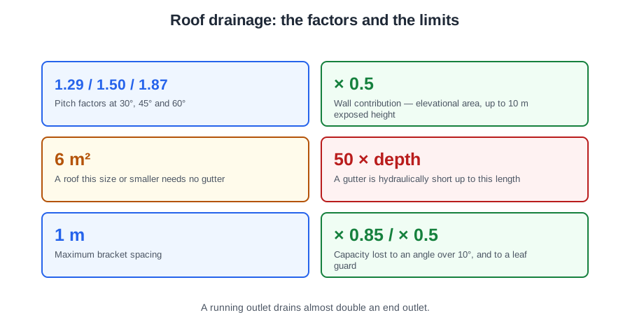
A gutter is only as good as the head of water that can build behind its outlet. It is hydraulically short if its length is not greater than 50 times the design depth of water; beyond that, the design capacity has to be reduced by a capacity factor.
For the terrace, the answer is not a bigger gutter. It is more outlets.
- A stop end outlet takes everything from one direction only.
- A running outlet, part way along a run, receives water from both directions, so it can drain almost double the area of an end outlet.
So a centre outlet is more efficient than two end outlets, and a run split into quarters by three outlets leaves each one handling a quarter of the flow. On a terrace, one downpipe on each party wall line is the usual and neatest answer.
To decide how many outlets you need, divide the expected flow rate from the roof by the flow rate of one outlet, using the manufacturer's figure. The gutter is laid with any fall towards the nearest outlet, and outlets should not be located close to a change in direction.
Several details quietly take capacity away:
- A gutter laid at a nominal gradient of 3 mm/m or less is designed as level. In practice a fall of about 1 to 3 mm per metre, roughly 1:600, is good workmanship.
- Support brackets at maximum 1 m intervals, so the run holds its line when full.
- Where a gutter contains one or more angles greater than 10°, the design capacity is multiplied by 0.85. Angles should be avoided close to an outlet.
- Where an outlet from a non-flat soled gutter has a strainer or leaf guard, the capacity is multiplied by 0.5. A balloon grating halves the design.
Gutters must also be laid so that any overflow above the design capacity discharges clear of the building. Where a downpipe discharges onto a lower roof or a paved area, fit a pipe shoe; and where a roof of more than 25 m² effective area discharges through a single downpipe onto a lower roof, add a distributor pipe so the flow spreads and does not over-top the receiving gutter.
Keeping it working
A rainwater system needs regular checking and cleaning, because it can get blocked with leaves. A blocked gutter overflows down the wall and into the fabric of the building.
How much maintenance a system needs depends on trees close to the building, the material the gutter is made from, and the age of the installation. It does not depend on the height of the gutter — height changes how you reach it, not what it needs.
Profiles matter to the customer as well as the calculation: half round is the domestic standard; ogee the ornamental Victorian pattern often required on period terraces; square section pairs with square downpipes; high capacity profiles suit larger and steeper roofs.
Where rainwater is harvested, BS 8515 applies. Storage is the lesser of 5 per cent of the annual rainwater yield or 5 per cent of the annual non-potable demand, about 18 days of supply. Yield is the collection area times the rainfall depth, reduced by a yield coefficient of about 0.7 to 0.8 and a filter efficiency of about 0.9; demand is about 50 litres per person per day. Harvested rainwater pipework must be marked and labelled so it can never be confused with wholesome water.
🔢 The numbers worth memorising
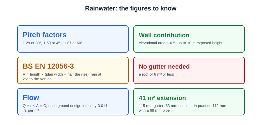
- Pitch factors
- 1.29 at 30°, 1.50 at 45°, 1.87 at 60°
- Wall contribution
- elevational area × 0.5, up to 10 m exposed height
- BS EN 12056-3
- A = length × (plan width + half the rise), rain at 26° to the vertical
- No gutter needed
- a roof of 6 m² or less
- Flow
- Q = r × A × C; underground design intensity 0.014 l/s per m²
- 41 m² extension
- 115 mm gutter, 63 mm outlet — in practice 112 mm with a 68 mm pipe
- Downpipe
- at least the size of the gutter outlet
- Hydraulically short
- length no more than 50 × the design depth
- Running outlet
- drains almost double an end outlet
- Gutter fall
- 3 mm/m or less is designed as level; about 1:600 in practice
- Bracket spacing
- maximum 1 m
- Angle over 10°
- capacity × 0.85; strainer or leaf guard × 0.5
- Distributor pipe
- roof over 25 m² discharging onto a lower roof
- Rainwater harvesting
- BS 8515 — about 18 days, demand 50 l/person/day
⚠️ Where people go wrong
- Sizing a gutter from the tape measure. The effective area can be nearly double.
- Forgetting the wall above a roof. It adds half its elevational area.
- Using both methods together, or a rafter-length method.
- Reading the gutter table down to an area below yours.
- Confusing 110 mm soil pipe with a rainwater downpipe.
- Answering an overflowing long gutter with a bigger gutter. It needs more outlets.
- Putting an outlet close to a change in direction.
- Fitting a balloon grating and expecting the table capacity. It halves it.
- Falling a gutter away from the nearest outlet.
- Discharging a large roof onto a lower one through a single downpipe with no distributor.
- Judging maintenance need by gutter height rather than trees, material and age.
- Leaving harvested rainwater pipework unmarked.
📝 10-Question Self-Test
Straight from the Level 3 course question bank. Click an option to see whether you got it right — the explanation appears instantly, and there is nothing to submit.
A stop end outlet only receives water from one direction. Move it part way along the run and it becomes a running outlet, taking flow from both sides, so it drains close to double the area — the capacity goes up. It does not increase the fall needed; gutters sized from Approved Document H Table 2 are taken as laid level.
Gutter size follows the water it has to carry, and that depends on the effective area of roof draining into it. Approved Document H3 Table 2 lists the largest effective roof area each gutter size will take, together with its outlet size. Tile colour and fascia material are appearance and fixing choices; they change nothing about the flow arriving.
Filling the gutter shows whether it drains to the outlet without ponding and whether any joint leaks; that is the test for both soundness and performance.
The two offset bends that bring the downpipe in from the gutter outlet to the wall form a swan neck.
Standard domestic round PVC-U rainwater downpipe is 68 mm, serving a 112 mm half-round gutter; 65 mm square downpipe is the square-section equivalent. 110 mm is soil and vent pipe, 40 mm is a bath or sink waste, and 63 mm is not a rainwater size.
Eaves gutters are supported on fascia or rafter brackets fitted not more than 1 m apart. BS EN 12056-3 National Annex NE.2.2 and BS 8000-13 3.1.1.6 give it as a recommendation rather than a limit, and closer centres are used where heavy snow is expected.
Every PVC-U gutter fitting has a rubber seal and a thermal expansion mark, with about a 10 mm gap built in; push the gutter to the mark and every fitting takes part of the movement. BS 8000-13 3.1.2.11 sends you to the manufacturer sitework instructions for the gaps and their intervals.
Age, the site (trees, exposure) and the material all decide how often a gutter needs clearing or attention. Its height changes how you reach it, not what it needs.
Leaves, moss and silt collect in gutters and outlets; a blocked gutter overflows down the wall and into the fabric, which is the reason for the routine check.
The effective drained area allows for the pitch of the roof, so the calculator needs the angle as well as the plan size.
Going further: the lessons behind this article
This article is the public answer. Unit 334 of the Level 3 course takes the same ground to the depth the exam and the synoptic assignment ask for, in 3 lessons:
- Effective roof area: pitch, walls and the two accepted methods
- Sizing the gutter, the outlet and the downpipe
- Terraces, outlet positions and keeping a rainwater system working
- Sanitation systems: the Unit 334 guide — every article on this unit in one place
- All PlumbMate articles — Level 1, 2 and 3
- The Level 3 course — the whole 8202-35 Diploma