A customer wants a second WC in a converted store room under the stairs. There is no way to reach the soil stack with a 100 mm branch at a workable fall.
The short answer
A WC macerator turns that job from impossible into ordinary — provided there is also access to a WC discharging directly to a gravity system. In other words, a macerator may add a WC; it may not be the only WC in the building. The unit must meet BS EN 12050-1 or BS EN 12050-3.
And the same theme runs through this whole section. Almost every appliance here carries a number set by a regulation rather than by preference: 6 litres for a WC flush, 7.5 litres per hour per urinal position, one WC for up to four occupants, 600 mm clear in front of a pan.
WC macerators
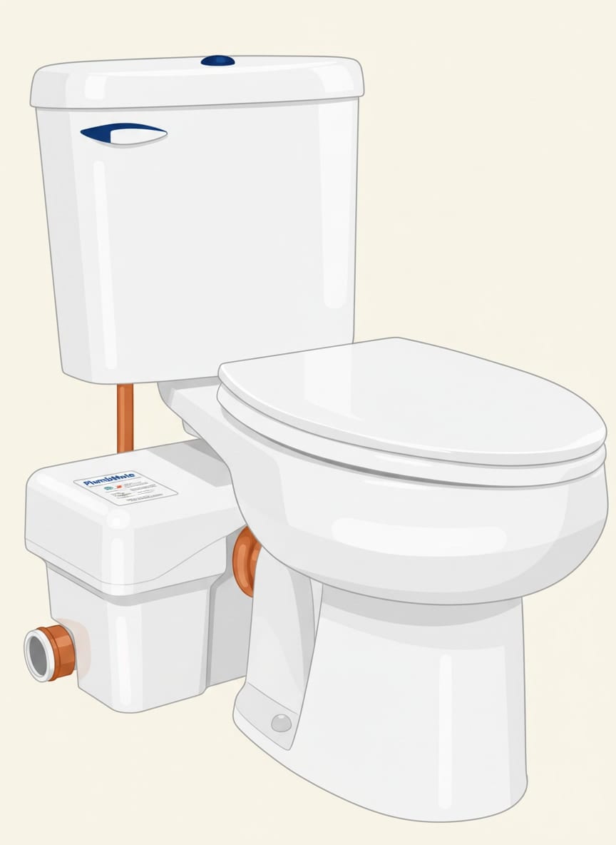
The pan discharges into the drum. A float or diaphragm switch rises with the water and starts the motor. Stainless steel blades break the solids up and suspend them in the liquid, and the pump forces that mixture up through a non-return valve into the discharge pipe. A small air valve with a charcoal filter opens during the cycle to stop a vacuum forming, and closes at rest so odour cannot escape.
The outlet pipework is where the installation is won or lost:
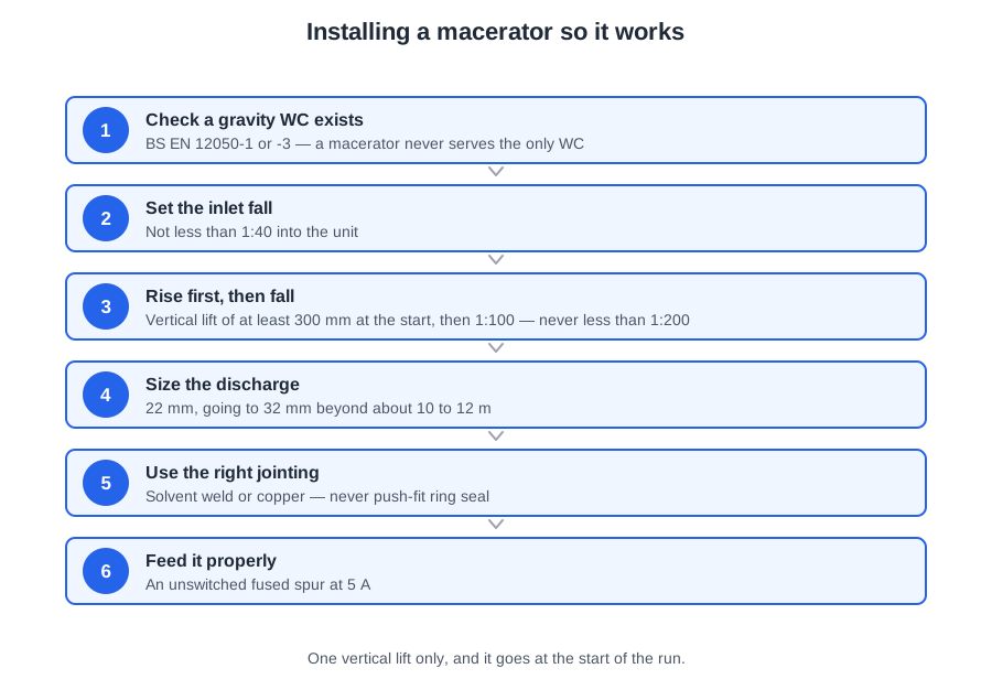
- It rises vertically within 300 mm of the unit before any horizontal run, keeping frictional loss off the pump.
- Long radius and 45° bends, never knuckle elbows. In solvent weld plastic, form a 90° from two 45° bends.
- Flexible connections at inlet and outlet, to minimise noise and vibration.
- Plastic discharge pipe must be solvent weld, not push fit. Copper is equally suitable.
- The horizontal run falls to the stack, typically 1:100, never less than 1:200.
- 22 mm suits most units; where the horizontal run exceeds about 10 to 12 m, most manufacturers ask for 32 mm.
Deburr every cut and wipe off excess solvent cement, or the bore narrows and the run blocks. And on the inlet side, the unit does not suck: everything entering it arrives by gravity at a fall of about 1:40, which is why a shower connected to a macerator needs its trap set high enough above floor level.
The unit normally sits directly behind the WC. Where it goes through a wall, keep the extension to 150 to 200 mm at most, and never install it under a floor. Boxed in, the panel must come off for maintenance. Electrically it needs an unswitched fused spur with a 5 A fuse.
Three faults worth memorising:
- Running long after the flush → a blockage around the pump.
- Not starting at all → the float switch.
- Slow discharge from the pan with the pump running properly → a blocked carbon air filter.
One more thing before you open a unit. When you work with bodily waste the biggest hazard is not electricity or noise: it is contact between contaminated material and an open wound. Cover cuts, wear gloves, and take up the hepatitis A vaccination employers now expect.
Waste water lifters and disposal units
A basement conversion where the sewer is above the new floor level. A waste water lifting plant collects the discharges in a sealed tank and pumps them up into the gravity drain.
The tank bottom slopes so solids are guided to the pump and sediment does not build up. The unit carries a permanent level control that raises an alarm on high water level, an inspection cover for access to the built-in non-return valve, and pressure sensing that reads the level without moving parts.
BS EN 12056-4 covers lifting plants, and sets the minimum discharge sizes: DN 80 for non-macerating faecal plant, DN 32 for macerating faecal and for faecal-free plant.
Two layout features matter more than any other:
- The discharge pipe is taken up into a backflow loop that rises above the level of the sewer before it drops into the drain, so nothing can flow back when the sewer runs full.
- Air admittance valves must not be fitted to the discharge pipework. A faecal lifting plant is vented to open air above roof level.
A larger domestic pumping station is the recommendation where eight to thirteen people are served, and those units carry a high level alarm as standard. A lifter is also the answer where a building sits too far from the sewer for a gravity run.
Which appliances may be connected depends on the unit, and one is a standing exception: a kitchen sink is not suitable — fat, grease and food solids foul the tank and the pump. A shower tray, bath and hand basin are all normal connections. And for the detailed method of positioning and fixing, the source is the manufacturer's instructions, not a British Standard or the Approved Document.
A sink waste disposal unit fits into a ready-made hole of 89 to 90 mm, usually in the cutlery bowl. A standard 40 mm trap with a 75 mm seal fits the outlet, with the branch kept short and steep; an industrial type unit gets a 50 mm trap with a 75 mm seal. Power comes from a fused spur, typically 10 A, normally with 30 mA RCD protection, and the unit must have an accessible thermal trip cut-off that stops it if the blades jam or the water flow fails.
Wet rooms
A customer who finds walking difficult asks what could replace the bath. A raised tray with a grab rail still has a step; a bi-fold door still has a threshold. The sensible recommendation is a walk-in wet room, because a level access floor removes both obstacles at once.
A wet room is a waterproofed, or tanked, area where the room itself becomes the enclosure. Instead of a tray there is a drain point set into the floor, and the floor is laid to fall towards it.
Tiles and grout are not waterproof. Silicone in a corner is not waterproof. What keeps water out of the structure is tanking: a continuous waterproof membrane laid over the floor and up the lower walls, sealed at the junctions, and tiled over. On a sunken former it goes between the former and the finished floor covering.
So when the question is what waterproofs the building fabric in a wet room, the answer is the tanking membrane — not epoxy grout, not a cement backer board, not a polythene DPM under a screed.
The floor is laid sloping so waste water runs to the gully, central or at the perimeter. When the gully goes in, the factor that matters most is getting the angle of fall and the finished floor level right. A floor laid dead level leaves standing water; a floor falling away from the gully sends water at the walls and the door.
A floor drain is normally connected to a branch of DN 50 to 100, so it is not at risk of self-siphonage — but a floor gully in a rarely used room can lose its seal by evaporation.
The advantages, worth being able to state: level access, suiting a wheelchair user or anyone unsteady; easy to clean, with no tray rim or enclosure; less likely to leak, because the whole floor is waterproofed rather than one tray; a good fit for a small bathroom; a free floor area that suits underfloor heating; and a cost similar to a tray and enclosure with less maintenance.
How many appliances, and how much space
BS 6465-1 sets the scale of provision (note it is BS 6465, not 6564):
| Appliance | Number per dwelling |
|---|---|
| WC | One for up to four occupants, two for five or more |
| Wash basin | One, and one adjacent to every WC |
| Bath or shower | One for every four people |
| Kitchen sink | One |
BS 6465-2 deals with space, and it separates the appliance space — the footprint of the appliance — from the activity space, the clear floor area a person needs to use it.
- WC: activity space 800 mm wide by 600 mm deep in front of the pan. So the least clear distance in front of a close-coupled WC is 600 mm.
- Domestic wash basin: 700 × 1000 mm; a hand rinse basin 600 × 800 mm.
- Appliance spaces: bath 1700 × 800 mm, shower 900 × 900 mm, washing machine 600 × 600 mm.
Activity spaces are allowed to overlap, which is what makes small bathrooms and cloakrooms work at all. What they may not do is disappear. The rule of thumb on site: set the appliances out on the floor before you fix anything, and check that a person can stand, turn and sit without meeting a wall, a radiator or an open door.
New dwellings also need a visitable toilet on the entrance level, and for that WC the depth of the activity space in front of the pan is increased beyond 600 mm so somebody using a wheelchair can transfer.
Two WC patterns are worth telling apart. A wash-down pan is cleared by the weight and momentum of the flush water alone. A siphonic WC clears its contents by a difference in air pressure: the flush starts a siphon in the trapway and atmospheric pressure pushes the contents out, which is why siphonic pans are quieter and more positive.
Other selections come up on jobs. Floor-mounted taps suit a freestanding roll top bath, which has no rim or wall behind it. And materials change the aftercare: an acrylic bath scratches and dulls under abrasive or solvent cleaners, so at handover the customer is told to use only what the manufacturer recommends.
Upper floor bathrooms mean pipes crossing joists, and the joist is a structural member. Approved Document A limits a notch to one eighth (0.125) of the joist depth: on a 195 mm joist that is 24 mm. Cut deeper and you have weakened the floor you are standing on.
WC flushing volumes
A 1996 cistern has cracked and the customer has seen a dual flush unit online. Schedule 2 paragraph 25 decides what may go in, and almost every question about WC flushing traces back to it.
No flushing device for a WC pan may give a single flush exceeding 6 litres, and that limit has applied since 1 January 2001. Between 1 July 1999 and that date a transitional arrangement allowed 7.5 litres. Where the device gives flushes of different volumes, the lesser flush may not exceed two-thirds of the largest — so a 6 litre full flush allows a maximum reduced flush of 4 litres.
The pan must clear effectively with a single flush, or with the largest of the flushes. That is why the pan and the device are approved together as a suite: the largest flush is what gets tested, and the reduced flush is a bonus on top.
A cistern installed before 1 July 1999 may be replaced by a cistern of similar volume, single or dual flush — but a single flush cistern may not be replaced by a dual flush one. The reason is the pairing: a pan designed to clear on 9 litres may not clear on 4, so the user flushes it twice and the conversion uses more water than before. Note the limit of the principle too: suite approval is a WC rule and does not extend to urinal bowls.
Every flushing cistern except a pressure flushing cistern must be marked internally with an indelible line showing the intended flush volume, together with an indication of that volume. Indelible and inside, so it cannot wear off or be removed. A dual flush device must have a readily discernible method of actuating each volume and instructions marked on the cistern or displayed nearby — two identical unmarked buttons do not satisfy this, and they are everywhere.
A siphon is valveless. There is no seat to wear, so it is very reliable at not leaking, but it needs physical effort and can be stiff. A drop valve is easy to operate and gives a clean dual flush, but it is a mechanical seal, so it can leak quietly straight down the pan where nobody notices — the single largest source of unnoticed domestic water waste.
A warning pipe is an overflow pipe whose outlet is where the discharge can readily be seen. Every flushing cistern needs one or a no less effective device, except a pressure flushing cistern and a urinal cistern. Where a warning pipe discharges into a WC pan it must do so into the air, not less than 150 mm above the top edge of the pan.
An internal overflow is accepted as no less effective on condition that a strainer is fitted at or upstream of the float-operated valve. It matters because an internal overflow gives no external signal at all, and the strainer removes the commonest cause of the valve failing to close: grit on the seat.
Urinals
A washroom with a 2100 mm slab and a cistern that fills day and night whether anybody has used the room or not. Both the size of the flush and the way it is triggered are set by the Regulations, and an uncontrolled cistern breaks them.
A urinal flushing device must supply no more water than is necessary for effective flow over the internal surface and for replacement of the fluid in the trap. The requirement is deemed satisfied where an automatically operated cistern fills at not more than:
- 10 litres per hour for a cistern serving a single urinal.
- 7.5 litres per hour per bowl or stall, or per 700 mm width of urinal slab, for a cistern serving two or more.
Work the slab out: 2100 ÷ 700 = 3 positions, and 3 × 7.5 = 22.5 litres per hour. The common error is to call a slab one appliance and apply the single-urinal figure of 10 l/h, which undersizes the flush by more than half. The multiple rate is lower per position because the flush is shared more efficiently.
Except where the urinal is flushed manually, or automatically by electronic means after use, the supply pipe must have an isolating valve controlled by a time switch and a lockable isolating valve, or another equally effective automatic device. A cistern with no control at all contravenes the Regulations on the undue consumption limb.
Two automatic controls compared. Hydraulic impulse control only fills when water is drawn nearby, so it follows use — but it depends on users washing their hands and degrades in hard water. Electronic movement detection is the technically superior control, because it detects the thing you actually want to detect, and battery life is often over two years.
A pressure flushing valve is a self-closing valve fed directly from a supply or distributing pipe. It has hard limits: it may not be installed in a house, nor in any building where a minimum flow rate of 1.2 litres per second cannot be achieved at the appliance. Serving urinals it must deliver not more than 1.5 litres per bowl or position each time — a maximum, the opposite of the cistern rates, which are ceilings on fill rate.
Wherever it connects to a supply or distributing pipe, the arrangement must include a permanently vented type DC pipe interrupter, not less than 300 mm above the spill-over level. That is the backflow protection for a fluid category 5 appliance.
A cisternless urinal puts the pieces together: a solenoid valve upstream, a DC pipe interrupter, and an infrared sensor that typically needs a presence of about ten seconds so it ignores somebody walking past.
And one distinction: where a single distributing pipe flushes six WCs and four urinals, it may not also serve the washbasins. The same cistern may serve them, but by a separate distributing pipe. The distinction is the pipe, not the cistern.
🔢 The numbers worth memorising
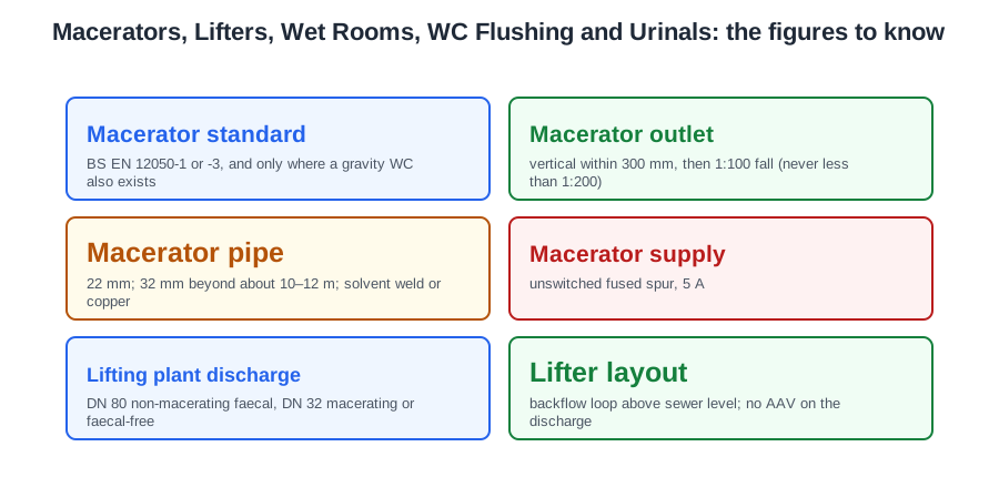
- Macerator standard
- BS EN 12050-1 or -3, and only where a gravity WC also exists
- Macerator outlet
- vertical within 300 mm, then 1:100 fall (never less than 1:200)
- Macerator pipe
- 22 mm; 32 mm beyond about 10–12 m; solvent weld or copper
- Macerator supply
- unswitched fused spur, 5 A
- Lifting plant discharge
- DN 80 non-macerating faecal, DN 32 macerating or faecal-free
- Lifter layout
- backflow loop above sewer level; no AAV on the discharge
- Disposal unit
- 89–90 mm hole, 40 mm trap, 75 mm seal, about 10 A
- Wet room waterproofing
- the tanking membrane, under the finish and up the walls
- WC provision
- one for up to four occupants, two for five or more
- WC activity space
- 800 mm wide × 600 mm deep in front of the pan
- Appliance spaces
- bath 1700 × 800, shower 900 × 900 mm
- Joist notch limit
- one eighth of the depth — 24 mm on a 195 mm joist
- Maximum single flush
- 6 litres since 1 January 2001
- Reduced flush
- no more than two-thirds of the largest — 4 litres on a 6 litre flush
- Warning pipe into a pan
- into the air, 150 mm above the top edge
- Single urinal
- 10 l/h; two or more 7.5 l/h per position or per 700 mm of slab
- Pressure flushing valve
- needs 1.2 l/s; 1.5 litres per urinal position; never in a house
- Pipe interrupter
- type DC, 300 mm above the spill-over level
⚠️ Where people go wrong
- Fitting a macerator as the only WC in a building.
- Running the macerator outlet horizontally straight off the unit, or in push fit.
- Using knuckle elbows on a macerator discharge.
- Expecting a macerator to draw from an appliance. Everything reaches it by gravity.
- Connecting a kitchen sink to a small waste water lifter.
- Fitting an air admittance valve to a lifter’s discharge pipework.
- Calling grout, silicone or a backer board the waterproofing in a wet room.
- Laying a wet room floor level, or falling away from the gully.
- Notching a joist deeper than an eighth of its depth.
- Replacing a single flush cistern with a dual flush one.
- Reading the reduced flush as the tested one. The largest flush is what clears the pan.
- Accepting two identical unmarked dual flush buttons.
- Fitting an internal overflow with no strainer at or upstream of the float valve.
- Treating a 2100 mm slab as one urinal. It is three positions.
- Leaving a urinal cistern with no time switch or automatic control.
- Fitting a pressure flushing valve in a house, or where 1.2 l/s is not available.
- Flushing urinals and serving washbasins off the same distributing pipe.
📝 10-Question Self-Test
Straight from the Level 3 course question bank. Click an option to see whether you got it right — the explanation appears instantly, and there is nothing to submit.
A siphonic WC pan has a double or restricted trapway that fills on flushing and starts a siphon which pulls the contents out; a wash-down pan is emptied only by the force of the flush water. Urinals do not siphon.
Acrylic baths scratch and dull under abrasive or solvent cleaners, so the customer is told at handover to use only the cleaners the manufacturer recommends.
Foul waste carries bacteria and viruses, and the way in is broken skin, so contact between contaminated material and an open wound is the significant hazard. Cover every cut with a waterproof dressing, wear gloves and wash before eating; employers expect hepatitis A vaccination for this work. Electric shock is a real risk on a macerator, but that comes from the supply, not from the waste.
A water service must not pass through a manhole or inspection chamber, where it would be exposed to sewage, damage and rodding; the route is taken around it.
Tiles, grout and silicone all let water through eventually. What keeps it out of the structure is the tanking membrane, a continuous waterproof sheet or liquid coating taken across the floor and up the lower walls, sealed at every junction and then tiled over. A cement backer board gives the tiles a stable, moisture resistant background, but it is not itself a waterproof barrier.
Positioning, fixing centres, clearances and pipe sizes differ from model to model, so the detailed method comes from the manufacturer's instructions supplied with that unit. Approved Document H and BS EN 12056-4 set what a lifting plant has to achieve, such as the backflow loop above flood level, the highest level waste water can rise to and not the level of the sewer, and ventilation to above roof level on a faecal plant, but neither tells you how to fix one particular machine.
Everything else in a wet room follows from the fall and the finished floor level. Get the fall wrong and water stands on the tiles or runs to the doorway; get the floor level wrong and the finish either stands proud of the door or drains the wrong way. Fitting the gulley tight to a wall is a layout choice, not a requirement, and on its own it makes nothing drain.
On a sunken former the waterproof layer goes between the former and the finished floor covering: a continuous tanking membrane, lapped up the walls and sealed at the junctions, so water passing the grout and tile bed cannot reach the structure. A sand and cement screed is a levelling and fall-forming layer, not a barrier, and laid over the former without tanking it leaves the floor porous.
The floor is laid to fall so that waste water runs to the gulley, which may be central or set at a perimeter drain. A dead level floor leaves standing water, which is a slip hazard and stains the grout, and a floor falling away from the gulley drives water at the walls and out through the doorway, which is exactly what the tanking is trying to avoid having to cope with.
The sensors, switching and timing that control an appliance are mounted on a printed circuit board, where copper tracks etched into the board replace individual wires. A distribution board is the tempting pick because it sounds electrical, but that is the consumer unit feeding circuits round a building, not a component carrier inside an appliance.
Going further: the lessons behind this article
This article is the public answer. Unit 334 of the Level 3 course takes the same ground to the depth the exam and the synoptic assignment ask for, in 6 lessons:
- WC macerators: how they work and how the outlet runs
- Waste water lifters and sink waste disposal units
- Wet rooms: tanking, falls and the floor gully
- Sanitary appliances: how many, how much space, which type
- WC flushing: volumes, devices and overflow protection
- Urinals: flush rates, controls and pressure flushing valves
- Sanitation systems: the Unit 334 guide — every article on this unit in one place
- All PlumbMate articles — Level 1, 2 and 3
- The Level 3 course — the whole 8202-35 Diploma