The call comes in as three words: “no hot water”. By the time you have the van unloaded and the airing cupboard open you could have lost an hour — while the person in the kitchen has watched this system every day for years.
The short answer
On a reported fault, particularly on an unvented system, the first method of finding out what will be needed to put it right is to ask the customer — before starting work. Not replace the inlet control group. Not pressure test the whole installation. Not order spares from the manufacturer. Those may follow, and only if the answers point that way.
Then, at the cylinder, three observations do most of the rest: which valve, when, and how hot. And one rule halves the work in a single step:
Pressure faults discharge cold. Temperature faults discharge hot.
Feel the discharge, or feel the pipe, before doing anything else.
What to ask, and why it counts as evidence
Four questions:
- The immediate history. When did it first occur? How did they notice it? Constant or intermittent, mornings only, worse when the heating is on?
- Have they seen water where it should not be? An unusual discharge around the vessel, or from a pipe outside the wall, points straight at a relief valve.
- Has the flow rate or the pressure changed? A drop in either points at a blockage, a blocked strainer or scale — not at anything electrical.
- Has anybody attempted a repair? Earlier work often has to be undone before the real fault will show itself, and a part fitted by somebody else may be the fault.
Add one more: what was the result of the fault? Lukewarm water at every tap is a different fault from scalding water at one. Cold water at the taps with the heating still working is different again.
Approved Document G 3.24 requires an unvented unit to be indelibly marked with a warning telling the user that a flow of hot water from the discharge pipe is a fault, and to switch the heater off and contact the installer. A customer repeating that back to you has handed you half the diagnosis.
BS 8558 makes the point in its maintenance guidance: in a single dwelling, responsibility for maintenance normally rests with the householder, and that includes identifying and correcting leakages and any discharges from overflow pipes or regular discharges from valves. The householder is therefore the only person who has been watching. Their description of a discharge — how often, how hot, how long — is data you cannot recover once the system has cooled down.
BS EN 806-5 clause 9.1 treats the user's senses as a diagnostic instrument too. Where damage or malfunction changes the odour, taste or colour of the water, corrective action is required; where immediate action is needed to prevent serious damage or contamination, the system is shut off at the service stop valve and the water supplier informed. A customer saying "the water has gone brown" is reporting a regulated condition, not a decorating problem.
Asking so that you get an answer
Ask in words the customer uses. "Is the expansion vessel discharging?" gets a blank look; "have you seen water dripping out of a pipe anywhere, inside or outside?" gets the answer. Ask them to show you rather than describe. Ask when the last service was and who did it.
Then write the answers down. They are the first entries in the job record, they are what you check your diagnosis against at the end, and if the fault is intermittent they are the only record of what it did on the day it was reported.
One warning. The customer reports symptoms, not causes. When somebody says "the thermostat has gone", hear it as "the water is too hot" or "the water is cold" and start from there. Their theory is worth testing, but it is not the diagnosis.
Where the procedure lives
You are in front of an unvented cylinder you have never seen before. The expansion valve is dribbling and you want to check the vessel pre-charge. What pressure should it be?
The step-by-step procedure for checking and recharging an expansion vessel is in the manufacturer's information. Not Approved Document G3, not the Water Supply (Water Fittings) Regulations, not BS EN 806 or BS 8558. Those documents say what must be achieved; only the maker of that cylinder gives the pre-charge figure, the order of dismantling and the part number of the replacement.
BS EN 806-5 clause 12 says it directly: routine maintenance on pipes, fittings, valves and appliances is carried out in accordance with the manufacturer's instructions, and procedures and frequencies shall be followed in accordance with them.
Clause 5 requires that all information relevant to the installation shall be readily available: the manufacturer's Technical Product Information for operation and maintenance retained and followed, the commissioning report as part of the documentation, and maintenance recorded and stored so the data is auditable. BS 8558 adds that the owner should have maintenance instructions and an accurate drawing particularly showing where pipe runs are concealed, with control valves clearly labelled and the labels renewed after redecorating.
Reading a fault diagnosis flow chart
Manufacturer fault-finding information usually takes three forms: known problems with their symptoms, a flow chart for identifying the problem, and the technique for replacing the component. Order parts by the model number of the equipment and the part number from the list, so what arrives fits.
A flow chart is a decision tree. It exists because a component such as a pressure reducing valve or an expansion vessel has several ways of failing that look identical from the outside.
Take excessive hot water from the taps on an indirectly heated cylinder. Is the thermostat set too high? If yes, reduce it. If no, is the motorised valve closing when the cylinder reaches temperature? If not, check the cylinder thermostat wiring, and check whether the thermostat is wired as the installation instructions require for that plan. If the wiring is right and the valve still does not close, the thermostat is faulty and is replaced.
Two rules make a chart work: start at the top, not in the middle, even when you think you know the answer — and change one thing at a time, so the chart is still telling you something on the next step.
What the service history tells you
The commissioning record and the service log are the system's memory. Between them they give the incoming static pressure when it was new, the expansion vessel pressure it was set to, what has been replaced since, and whether this fault has happened before.
A pre-charge that has fallen at every service is a vessel on its way out. A cut-out that has been reset before, with no cause recorded, is a thermostat that has been failing for a year. Where there is no history, treat the installation as unknown and inspect it as if you were commissioning it — nothing about it has been proved to you.
Reading the discharge
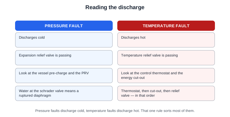
The rule works because the valves are designed for different jobs.
BS 5546 6.11.3 d): the expansion relief valve is there to discharge excess pressure if either the expansion vessel or the pressure reducing valve fails. It has no idea what temperature the water is; it opens on pressure alone, and on an unvented cylinder that pressure rise happens while the water is heating — so what comes out is the cold water sitting in the pipe and cool water from the cold side of the cylinder.
The temperature relief valve is a different device with a different job. Schedule 2 paragraph 23 of the Water Regulations requires one on every unvented vessel over 15 litres, located directly on the vessel, with enough capacity to ensure stored water never exceeds 100 °C. Typically it opens around 95 °C. When that valve lets go, scalding water and steam come out. It cannot be anything but a temperature fault.
BS 8558 puts the pressure half in one sentence: discharge from an expansion valve, or from a cistern warning pipe, indicates a possible malfunction of a pressure reducing valve, pressure limiting valve, expansion vessel or control valve. Four suspects, all on the pressure side.
Identify the valve first. The expansion valve sits on the cold inlet close to the vessel; the T&P valve is factory fitted into the top of the vessel itself. They may share a manifold to one tundish, so trace the discharge back rather than guessing.
Then the timing:
- Appears only while heating, stops when it cools → expansion.
- Runs continuously, hot or cold, heating or not → a valve or the PRV passing.
- Shows up only when water is drawn off → not a discharge fault at all. It is a flow fault.
Why the tundish has to be where you can see it
Approved Document G 3.54 requires the tundish to be vertical, in the same space as the unvented system, as close as possible to and lower than the safety device, with no more than 600 mm between valve outlet and tundish. Clause 3.55 adds that any discharge should be visible at the tundish, and Schedule 2 paragraph 19 requires discharges to be made in a safe and conspicuous manner.
Those requirements exist for the diagnosis as much as for the hydraulics. A discharge nobody can see tells nobody anything at all. Put the tundish in a loft or behind a bath panel and the cylinder can discharge for a year: the customer never reports it, the vessel never gets recharged, and the first anyone knows is when something worse fails.
Where a discharge might not be apparent — a dwelling occupied by someone with impaired vision or mobility, for example — paragraph 3.55 says consideration should be given to a device that warns when a discharge takes place.
One way to hold the whole skill: fault finding is commissioning backwards. Commissioning proves the system in order — fill, vent, pressure, temperature, controls, safety devices, record. Fault finding walks that order backwards from the symptom until you reach the thing that is not doing its job.
The three fault signatures
Almost every unvented complaint arrives as one of three patterns. Learn the three and you will name the fault from the doorway.
One: it dribbles while heating, and stops when cold
Water expands as it is heated and that expansion has to go somewhere. If it has nowhere to go, the pressure climbs past the valve setting and the valve does exactly what it exists for. When the system cools the pressure drops back and the dripping stops.
The cause is that the expansion vessel has lost its gas charge or is waterlogged — or, on a bubble-top cylinder, the air gap inside the cylinder has been lost. This is the commonest unvented fault of the lot, and the discharge is cold. It is not the check valve passing, not the thermostat failed high, and not a blocked strainer.
On a bubble-top cylinder there is no external vessel: expansion is taken up by an air gap held at the crown. That gap slowly dissolves into the water and disappears. Draining down and refilling re-forms the bubble.
Two: scalding water and steam
This is a temperature control failure, and both layers have already let go. AD G 3.17 requires two independent safety devices in addition to the control thermostat, and BS 5546 6.11.2.2 sets the order in which they act as temperature rises: thermostat, then energy cut-out, then temperature relief valve.
So when you see the third device working, the first two have already failed. The valve is reporting, not failing — replacing it fixes nothing.
It is also not normal operation. A properly working cylinder never relieves on a heat-up cycle. Anyone who tells the customer "they all do that" is describing a system with one layer of protection left.
Three: a burst of flow, then a trickle
The tap runs well for a few seconds, then dies back to a weak stream. Nothing is discharging. This is not a discharge signature at all — it is a flow one.
What you are watching is the stored hot water leaving the cylinder at full pressure, followed by the refill rate limiting the flow once the store is empty. The refill rate is limited by a blocked in-line strainer on the cold inlet. It is not the vessel collapsing under demand and not a failed thermostat — the water that did come out was hot and at good pressure.
Two more patterns worth carrying. Cold water running constantly from the expansion valve is usually incorrect pressure due to a malfunction of the pressure reducing valve — check and replace the PRV. Cold water running constantly from the T&P valve usually means a joint failure of the pressure reducing valve and the pressure relief valve, so both are checked and replaced.
| What you see | What it means | First check |
|---|---|---|
| Dribble while heating, stops when cold | Expansion vessel charge lost, waterlogged, or air gap gone | Pre-charge at the schrader valve |
| Cold water running constantly | Pressure reducing valve malfunction | Static and dynamic pressures |
| Hot water and steam discharging | Temperature control failure — thermostat and cut-out both gone | Switch off the heat source, then all thermal controls |
| Good flow, then weak flow | Blocked in-line strainer limiting the refill | Isolate, drain, remove and clean the strainer |
Four defects that hide on a working system
Some faults are not failures. They were installed. The system runs, the customer is happy, and nothing announces the problem until the day something else goes wrong and the protection that should have caught it is not there. That is why a service or fault visit starts with a look round, not a test.
- Balanced cold from the wrong place. It must come from the cold feed to the vessel, after the pressure reducing valve and before the single check valve. The PRV then holds hot and cold at the same pressure, which mixer taps, shower mixers and TMVs need to blend safely. Taken from anywhere else: unbalanced pressures at the mixers, and a scald risk.
- No strainer. The in-line strainer keeps solid matter out of the PRV and everything downstream. Note which way round that is — fitting the strainer upstream of the PRV is correct practice, not a defect. Leaving it out is the defect.
- Missing or wrongly placed check valve. The single check valve stops hot water backflowing into the cold main, and it is what forces expansion into the vessel or the bubble rather than back up the supply pipe. Without it, expansion escapes up the main and a failed vessel produces no symptom at all — until the mains pressure rises one night and the cylinder has nowhere to expand into.
- Relief valve fitted too low. BS 5546 6.11.2.1 c) requires the temperature relief valve within the top 20 per cent of the water in the cylinder, preferably within 150 mm of the top. AD G 3.38 requires it directly on the vessel; 3.39 says it should be factory fitted, not disconnected other than for replacement, and not relocated into any other device or fitting. Fitted lower down it senses cooler water and lets the crown of the cylinder go past the temperature it exists to catch.
What to look at on a cistern, and on a vessel
On a vented system, one of the most important checks when inspecting an existing cistern is that the bearers and base are sound and fit for purpose. AD G 3.15 requires the platform to be flat, level and rigid, capable of safely withstanding the weight of the cistern filled to the rim, supporting the whole of the bottom, and extending at least 150 mm in all directions beyond it. A cistern full of water is a heavy thing sitting on old timber. Replace a metal cistern, or fit a larger plastic one, and the support is upgraded to suit.
On a hot water storage vessel, one of the most important checks is that the high limit thermostat is protected by a 3 amp fuse. Three related points come with it, each a distinct fault if wrong:
- An immersion heater is supplied through a fixed connection, not a 13 amp plug and socket.
- The cylinder thermostat is set to store at 60 °C for control of bacteria — not turned down to 45.
- The high limit thermostat must not reset itself. AD G 3.18 a) and BS 5546 6.11.2.1 b) both require a non-self-resetting energy cut-out.
Write down what you find. A defect you noticed and did not record is one you did not find.
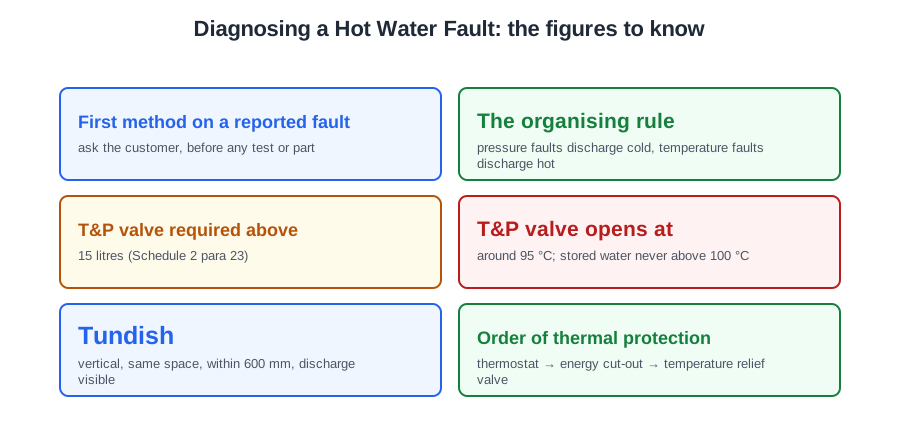
🔢 The numbers worth memorising
- First method on a reported fault
- ask the customer, before any test or part
- The organising rule
- pressure faults discharge cold, temperature faults discharge hot
- T&P valve required above
- 15 litres (Schedule 2 para 23)
- T&P valve opens at
- around 95 °C; stored water never above 100 °C
- Tundish
- vertical, same space, within 600 mm, discharge visible
- Order of thermal protection
- thermostat → energy cut-out → temperature relief valve
- Temperature relief valve position
- top 20 per cent of the water, preferably within 150 mm of the top
- Balanced cold take-off
- after the PRV, before the single check valve
- Cistern platform
- extends at least 150 mm beyond, holds the cistern filled to the rim
- High limit thermostat
- fused at 3 A, non-self-resetting
- Immersion supply
- fixed connection, never a 13 A plug and socket
- Stored temperature
- 60 °C
⚠️ Where people go wrong
- Starting with a pressure test or a new inlet group. Ask the customer first — a conversation often produces the repair with no testing at all.
- Taking the customer’s theory as the diagnosis. They report symptoms, not causes.
- Looking up a pre-charge figure in Approved Document G or the Water Regulations. It is in the manufacturer’s information.
- Starting a flow chart in the middle, or changing two things at once.
- Replacing a temperature relief valve that has discharged steam. It is reporting, not failing — the thermostat and cut-out have both already gone.
- Telling a customer a heat-up discharge is normal. A properly working cylinder never relieves on a heat-up cycle.
- Calling a burst-then-trickle a vessel or thermostat fault. The water that came out was hot and at pressure — it is the strainer.
- Guessing which valve discharged from a shared tundish. Trace it back.
- Fitting a tundish in a loft or behind a panel. A discharge nobody can see tells nobody anything.
- Calling a strainer upstream of the PRV a defect. That is correct practice — leaving it out is the defect.
- Assuming a working system has no defects. All four classics are invisible until something else fails.
- Noticing a defect and not recording it.
📝 10-Question Self-Test
Straight from the Level 3 course question bank. Click an option to see whether you got it right — the explanation appears instantly, and there is nothing to submit.
The user knows when it started, what it has done and whether anybody has already had a go at repairing it, and that history narrows the search before you touch a valve. Changing the inlet control group first is fitting parts at a symptom you have not identified, and it can leave the real fault in place.
The customer is the only person who saw the fault happen: when it started, whether anything discharged, whether the flow dropped away, whether anyone has already tried to fix it. That conversation costs nothing and points you at the right half of the system. Pressure testing the whole installation or ordering a set of spares first is work done before you know what you are looking for.
Heating working and hot water dead points at the branch that serves the cylinder alone: the hot water zone valve is not opening, or its motor or microswitch has failed, so the boiler never gets that call. A vessel that has lost its charge makes the expansion valve weep on reheat; it does not stop the water being heated.
An open vented cylinder is fed by gravity from the cistern above it. If the float operated valve sticks shut the cistern empties, the cold feed runs dry and every hot outlet stops. A blocked open vent is the tempting pick, but the vent carries no water in normal use — blocking it makes the system unsafe rather than stopping the flow.
Test before you replace. An expansion valve that passes is usually being fed too high a pressure, so check the reading on the outlet side of the pressure reducing valve first; a drifted or failed PRV is a common cause. Fitting an expansion valve with a higher setting raises the pressure the system runs at and buries the real fault.
The pre-charge figure, where the Schrader valve sits, and how the water side is dropped to zero pressure before the reading is taken are all specific to that unit, so the step-by-step comes from the manufacturer’s literature. Approved Document G3 and the Water Regulations say what the vessel has to achieve, not how to service it, and BS 8558, which with BS EN 806 replaced the withdrawn BS 6700, gives general guidance, not that unit’s procedure.
The manufacturer’s instructions tell you what the settings should be. Only the commissioning record tells you what they were, on this system, on the day: the reducing valve setting, the expansion vessel pre-charge, the thermostat and cut-out, and the relief valve checks. Comparing the two is often the whole diagnosis, because a setting that has drifted or been altered shows up at once.
A bubble top cylinder takes up expansion in an air gap held at the crown of the vessel instead of in an external one. That air slowly dissolves into the water, so the expanding water has nowhere to go and the expansion valve relieves the extra pressure from time to time. Draining down and refilling re-forms the bubble. A temperature relief valve jammed shut would not discharge at all.
Water expands as it heats, and if the vessel has lost its charge or the internal air gap has gone there is nowhere for it to go, so pressure climbs until the expansion valve lifts. As the system cools it falls back and the dripping stops. That timing is the giveaway, and the discharge is cold — a thermostat failed high would give you scalding water, not a cold dribble.
Scalding water and steam mean the temperature relief valve is open, and that is the third device in the chain. Approved Document G 3.17 requires two independent safety devices in addition to the control thermostat, and BS 5546 6.11.2.2 sets their order as thermostat, energy cut-out, then temperature relief valve. So the first two have already failed. This is never a normal reheat discharge.
Going further: the lessons behind this article
This article is the public answer. Unit 332 of the Level 3 course takes the same ground to the depth the exam and the synoptic assignment ask for, in 5 lessons:
- Questioning the end user before you touch anything
- Manufacturer instructions, flow charts and service history
- Reading the discharge: which valve, when and how hot
- The three fault signatures and what each one means
- Looking before testing: classic installation defects
- Hot water systems: the Unit 332 guide — every article on this unit in one place
- All PlumbMate articles — Level 1, 2 and 3
- The Level 3 course — the whole 8202-35 Diploma