Halfway through commissioning a new unvented cylinder the energy cut-out will not reset. It is a Friday, the customer wants a bath, and there is a blank Benchmark checklist on the worktop. What you do next is examined — and the wrong answers are all the tempting ones.
The short answer
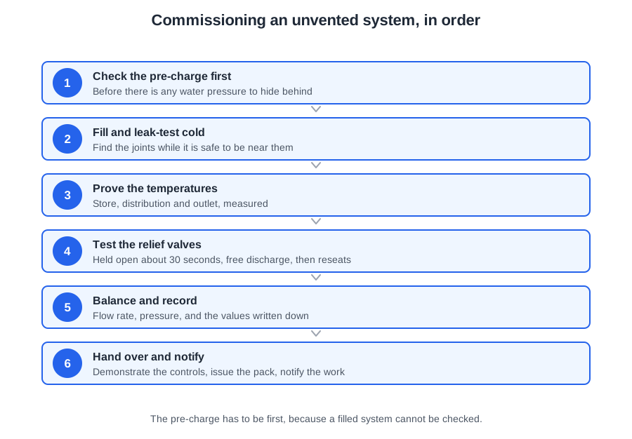
An unvented cylinder has no open vent pipe. Every job the vent used to do — taking up expansion, holding the pressure down, giving steam somewhere to go — is now done by a device. Commissioning is where each of those devices is proved, in an order that is not negotiable:
- Set the expansion vessel pre-charge, before any water goes in.
- Fill, vent and leak-test cold.
- Test the relief valves.
- Heat up — which is the check that validates step one.
Each step is where it is for a reason you can state, and stating the reason is usually the mark.
Why the pre-charge has to be first
Read the pre-charge at the schrader valve with a Bourdon gauge and top it up with a foot pump if it is low, to the cold fill pressure the manufacturer gives.
Why first? Because once there is water in the cylinder, the gauge reads the charge plus the fill pressure, not the charge on its own, and there is no way to separate the two. It is not that the water has to be hot, and not that the schrader valve leaks — after filling, the reading is simply a sum. Get it wrong and you have a system that discharges on every reheat for the rest of its life.
Step two: fill, vent, leak-test cold. Fill with all the hot taps open, draw from every outlet until it runs without spluttering, let the system stabilise, then close everything and go round the joints. Why here? Because everything after this step involves heat, and a weeping joint found on a hot cylinder is a far worse afternoon than the same joint found cold.
Step three: test the relief valves — before the heat-up, so that the first heat is protected. Testing them afterwards is testing them after the risk has already been taken.
The test has two halves. Lift or twist the lever and hold the valve open — about 30 seconds is usual — and look for a free discharge through the tundish. Then release it and confirm the valve reseats cleanly. A valve that opens and then weeps has failed the test even though it discharged. Both the expansion relief valve and the T&P valve are tested this way, and the same operation proves the D1, tundish and D2 arrangement carries the water away.
You do not bench test the valve, you do not read the gauge and wait for the pressure to fall, and you certainly do not heat the cylinder until a valve lifts on its own.
Step four: the heat-up, which checks step one
Heat the cylinder for the first time and watch. If the expansion relief valve discharges during the heat-up cycle, that is not normal and it is not a faulty valve. It means the pre-charge is wrong or the vessel has failed: the water has nowhere to expand into, so the pressure climbs until the relief valve does its job. Stop, put the vessel right, and start the commissioning again.
Safety devices against functional controls
Approved Document G paragraph 3.17 requires an unvented system to have a minimum of two independent safety devices in addition to the control thermostat. Paragraph 3.18 gives the acceptable approach: a non-self-resetting energy cut-out and a temperature relief valve or combined T&P valve.
Everything else on the inlet — the pressure reducing valve, the single check valve, the expansion vessel, the expansion relief valve — is listed as a functional control, although the expansion relief valve’s job is safety against pressure. Functional controls make the system work; the two safety devices stop the stored water reaching 100 °C. The exam asks you to tell them apart.
The temperatures you prove
A hot water system has to be hot enough to be safe and cool enough to be safe, and the two meanings of "safe" pull in opposite directions. Hot kills Legionella; cool prevents scalds.
On a storage system three devices watch the temperature, and they only work if each is set below the next:
- Control thermostat, 60 to 65 °C — the immersion stat on a direct cylinder, the cylinder stat on an indirect one.
- Energy cut-out, the non-self-resetting overheat device, set below the relief valve: a maximum of 90 °C, usually factory set between 85 and 89 °C.
- Temperature and pressure relief valve, at 95 °C.
All three sit under 100 °C, and that is the whole point: stored water above 100 °C at pressure flashes to steam the moment the pressure is released. Three devices set in the wrong relative order is one device with two spectators.
On an indirect system the boiler thermostat (typically 82 °C maximum) and boiler high limit stat (typically 90 °C) sit in the chain too. And the reason for 60 °C stored is ACOP L8 paragraph 59(a): avoid water temperatures between 20 and 45 °C.
At the outlet: 50 °C within one minute
BS 8558 clause 4.3.5.1.1 b) gives the commissioning check. The temperature at an outlet should be at least 50 °C within 1 minute of running, and the supply to any TMV should reach at least 50 °C within 1 minute as well.
So a basin tap run for one minute in a hotel and reading 44 °C is unacceptable. Correct storage at 60 °C does not excuse it — the water is arriving too slowly or too cool, which points to a long dead leg, poor insulation or an unbalanced secondary return, and all three have to be investigated rather than noted.
The matching cold figures are worth carrying: cold below 20 °C after running for up to 2 minutes, and cold never warmed above 25 °C on its way through the building. With secondary circulation, water should leave the calorifier at at least 60 °C and return at 50 °C or more (55 °C in healthcare).
At the bath: 48 °C, and what it actually proves
Approved Document G paragraph 3.65 limits hot water supply to a bath to a maximum of 48 °C, by an in-line blending valve or other temperature control device with a maximum temperature stop. Paragraph 3.66 wants a valve to BS EN 1111 or BS EN 1287 that cannot be adjusted above 48 °C by the user and that fails safe.
But confirming 48 °C tests more than the valve, and this is the point worth remembering. A thermostatic mixing valve can only hold its blend if its cold supply is stable. If the cold was taken from the wrong place — not the balanced cold take-off — the blend wanders every time another outlet runs. So a correct 48 °C proves the cold was taken from the right place for balance. It is the one commissioning check that catches a first-fix error made weeks earlier, by which time the cold branch is usually buried.
One more rule: where stored water can exceed 80 °C in normal operation — heat stores, solar collectors, solid fuel boilers with no intervening controls — paragraph 3.64 requires a device such as an in-line tempering valve to BS EN 15092 at the vessel outlet, so water entering the distribution does not exceed 60 °C.
Measure at the draw-off from the store first, then work outward, checking each successive outlet away from the vessel. With a secondary circuit, have the pump running while you read, and check the return just before it re-enters the cylinder: no more than 10 °C below the draw-off, and at least 50 °C.
Flow rate, pressure and balancing
BS 8000-15 clause 4.5: check each draw-off tap, shower fitting and float-operated valve for rate of flow against the specified requirements, carry out performance tests on connected specialist items, and where a test reveals a defect, remedy it and repeat the test until a satisfactory result is obtained.
When you performance test the outlets of a hot water system, the three things you measure are flow rate, pressure and temperature. Not hardness, not turbidity, not chlorine residual — those belong to water quality work.
The simple site tool is the weir gauge (weir cup): a slot down one side marked with flow rates, held under the running outlet, the height the water reaches giving the rate. Accurate within its range — but an excessive flow overtops the gauge and gives a false low reading. A combined pressure and flow meter reads both at once. Measure one outlet at a time.
BS EN 806-3 Table 2 gives the design figures, where 1 loading unit = 0.1 l/s:
| Draw-off point | Flow rate | LU |
|---|---|---|
| Washbasin, handbasin, bidet, WC cistern | 0.1 l/s | 1 |
| Domestic sink, washing machine, dishwasher, shower head | 0.2 l/s | 2 |
| Urinal flush valve | 0.3 l/s | 3 |
| Domestic bath | 0.4 l/s | 4 |
| Garden or garage tap | 0.5 l/s | 5 |
| Non-domestic bath, non-domestic sink DN 20 | 0.8 l/s | 8 |
A domestic bath is 0.4 l/s, with a minimum of 0.3 l/s at the outlet under simultaneous demand. The withdrawn BS 6700 figures — 0.3 l/s for a bath with 20 mm taps, 0.6 l/s for 25 mm — are the trap.
Take static pressure with nothing running and dynamic with the outlet open; the difference tells you how much the pipework is losing. On an unvented system compare both with the PRV setting and the manufacturer's limits — a static that is fine but a running pressure that collapses usually means a blocked strainer or an undersized branch.
Balancing a secondary circuit
Large secondary systems have bronze lockshield valves on every return leg, as close to the appliances as possible. Balance them by opening the valve on the longest circuit fully, then closing the lockshields on the shorter legs a little at a time, working back towards the cylinder, until every leg reaches the same temperature at the same time.
Proving the balance is a temperature job, not a flow job. The CIBSE Legionella guidance says to locate all subsidiary loops, determine the direction of flow, and take temperature checks at the end of each return leg at a time of no hot water demand. CIBSE’s commissioning target is 55 °C at the end of each return leg, with 50 °C as the absolute minimum (HSE guidance). Measuring the pump flow and dividing it between the loops proves nothing, and setting every regulating valve to the same position proves less.
Functional testing the controls
BS 7671 regulation 643.10 defines it: equipment is subjected to functional testing to verify it is properly mounted, adjusted and installed, and operates correctly. So to confirm an immersion heater operates safely, the test to do is a functional test — not a ring final circuit continuity test, not a prospective fault current test, not a phase sequence test, all of which test the circuit rather than the appliance.
In practice: call for hot water and confirm the motorised valve drives open, the pump runs, the boiler fires, the thermostat satisfies and shuts the system down, and the cut-out operates to the manufacturer's specification.
When commissioning finds a defect
Back to the energy cut-out that will not reset. The first thing is not recording the defect, not ringing the manufacturer, and not ordering the part. It is keeping the occupants safe. If the system cannot be left in a safe state it is isolated and temporarily decommissioned until the replacement arrives.
Then, for a defective component:
- Do not attempt a repair — it can invalidate the manufacturer's warranty.
- Contact the manufacturer first; they may want to inspect the component before it is replaced. Tell the supplier.
- Replace it only with a component approved by the manufacturer for that appliance, after advising the customer.
Never bridge the cut-out contacts to finish commissioning — that removes a safety device from a pressure vessel. Never fit "any cut-out of the same rating" from the merchant. And never leave the cylinder in service with the fault simply noted on the Benchmark record.
BS 8000-15 clause 4.1.3 is blunt: correct immediately items failing any test and retest them before further work proceeds. So an interim test finding a weeping compression joint on pipework about to be boxed in gets corrected and retested now — not noted and carried past, not tightened while accepting the earlier test because the pressure held for most of the period, and not left to bed in. Clause 4.1.2 explains why: interim tests exist precisely for work that will be concealed, and satisfactory completion of an interim test does not constitute a final test.
Where the defect is a shortfall in performance rather than a leak, check the drawings and confirm pipe sizes with the design engineer before altering anything, and check the set-up of pumps and accumulators against manufacturer data. Undersized pipe, too many fittings and badly set boosting equipment are the usual causes.
The records
BS EN 806-4 requires three, and none of them stays with the installer:
- 6.1.1 — a complete record of the pressure test, including the test procedure diagram, made and preserved.
- 6.2.2 — a complete record of the flushing procedure, retained and handed over to the building owner.
- 6.3.3 — a complete record of the disinfection procedure and its test results, handed to the building owner.
On a domestic job the commissioning record itself is usually the Benchmark Commissioning Checklist from the back of the appliance manual. It carries the date and time and the name and, for an unvented system, the registered operative identity card number — not a labour rate, not a National Insurance number, not a van registration. Also: the location; the amount of hot and cold storage; types and manufacturer of equipment; the type of pressure test and its duration; the incoming static pressure; flow rates and pressures at the outlets; the expansion vessel pressure; whether T&P valves are fitted; and the results of the tests on the discharge pipework.
It is signed by the operative and the customer and kept somewhere safe, because the next engineer to service the system will work from it.
Handover: what you leave, what you say, what you notify
The handover is not a formality: the customer is being given a pressure vessel with a maintenance requirement, and everything they need to keep it safe between visits has to come from you.
The manufacturer's commissioning and instruction manual is passed to the customer — not the merchant, not the Building Control Officer, not the clerk of works. The file you leave contains the manuals, the commissioning records and certificates (flushing and disinfection included), the Building Regulations compliance certificate, and an as-fitted drawing showing isolation valves, backflow prevention devices and the layout. BS 8558 clause 5.1.8 asks for a diagrammatic drawing so the identity and function of every valve can be determined.
The Domestic Building Services Compliance Guide section 5.0 b) adds two duties that carry marks: explain fully to the user how to operate the system in an energy efficient manner, and leave behind any user manuals provided by manufacturers. The completed Benchmark checklist goes to the householder where the work is in an existing dwelling — it is not kept by the installer for future warranty claims and not returned to the supplier.
The demonstration
BS 5546 clause 8.3.1: the user is given the operating instructions, and the correct operating procedure, the safety shut-off controls and the ancillary controls are demonstrated — shown, not just mentioned. Clause 8.3.2 covers precautions if the system is left off in freezing weather, and clause 8.3.3 requires the occupier to be advised in writing that regular maintenance by a competent person is needed.
Know where the line falls. Adjusting the temperature on a single point electric water heater can properly be explained verbally, and the cylinder thermostat is a control a householder can be expected to adjust from time to time. But replacing an immersion element, draining and refilling an unvented cylinder, resetting a thermal cut-out, altering a pressure reducing valve, recharging an expansion vessel or setting a motorised valve are not customer jobs.
Three things must be said at handover on an unvented system:
- It needs an annual service.
- The energy cut-out is a hand-reset device, so a trip means something is wrong.
- Any discharge at the tundish means call an installer.
Those are what the customer needs to keep the system safe between visits — not the BBA number, the model number or the length of the warranty.
Notification, and the clocks
Installing an unvented hot water system is notifiable building work. Approved Document G paragraph 3.41: it must be notified to the building control body before work commences. Paragraph 3.42 lifts that where the installer is registered with a competent person scheme — there is then no advance notice: the installer self-certifies, and the occupier is given a building regulations certificate of compliance, usually issued by the scheme operator.
Regulation 16A requires that certificate to reach the occupier within 30 days of completion, with a notice or copy to the building control body within the same 30 days. The BCB accepts the certificate as evidence of compliance and does not inspect.
For the separate notice of completion of commissioning, paragraph 3.78 gives two timescales: not more than 5 days where the work is done under a building notice, full plans or an initial notice, and not more than 30 days where it is done by a person registered with a competent person scheme. Paragraph 3.79 makes the registered person responsible for giving it, and 3.80 warns that until the BCB has it, it is unlikely to issue a completion certificate.
🔢 The numbers worth memorising
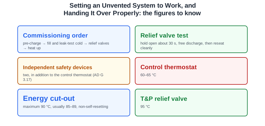
- Commissioning order
- pre-charge → fill and leak-test cold → relief valves → heat up
- Relief valve test
- hold open about 30 s, free discharge, then reseat cleanly
- Independent safety devices
- two, in addition to the control thermostat (AD G 3.17)
- Control thermostat
- 60–65 °C
- Energy cut-out
- maximum 90 °C, usually 85–89, non-self-resetting
- T&P relief valve
- 95 °C
- Legionella band to avoid
- 20 to 45 °C (ACOP L8 59(a))
- Outlet check
- at least 50 °C within 1 minute
- Cold check
- below 20 °C within 2 minutes; never warmed above 25 °C
- Secondary return
- within 10 °C of the draw-off, and at least 50 °C
- Bath limit
- 48 °C, valve to BS EN 1111 or BS EN 1287
- Store above 80 °C
- tempering valve to BS EN 15092, distribution not above 60 °C
- Performance test measures
- flow rate, pressure and temperature
- Domestic bath flow
- 0.4 l/s (4 LU); 1 LU = 0.1 l/s
- Balance proved at
- CIBSE target 55 °C at the end of each return leg, at no demand; 50 °C absolute minimum (HSE guidance)
- Immersion heater proof
- functional test (BS 7671 643.10)
- Certificate of compliance
- to the occupier within 30 days
- Notice of completion of commissioning
- 5 days under a building notice, 30 days under a scheme
⚠️ Where people go wrong
- Reading the pre-charge after filling. The gauge then shows charge plus fill pressure — there is no way to separate them.
- Testing the relief valves after the heat-up. That is testing them after the risk has been taken.
- Passing a relief valve that discharges but then weeps. It has to reseat cleanly.
- Calling a discharge on the first heat-up a faulty valve. The pre-charge is wrong or the vessel has failed — put it right and start again.
- Counting the pressure reducing valve or expansion vessel as a safety device. They are functional controls.
- Setting the cut-out above the relief valve. Three devices in the wrong order is one device with two spectators.
- Accepting 44 °C at an outlet because the store reads 60. The one-minute, 50 °C check has still failed.
- Treating the 48 °C bath check as only a valve test. It also proves the cold came from the balanced take-off.
- Trusting a weir gauge on a high flow. An excessive flow overtops it and reads low.
- Using the withdrawn BS 6700 bath figures. BS EN 806-3 gives 0.4 l/s.
- Proving a balance by flow. It is proved by temperature at the end of each leg, at no demand.
- Bridging a cut-out to finish the job, or fitting any part of the same rating. Manufacturer-approved only, after advising the customer.
- Noting a failed interim test and carrying on. Correct it and retest before further work proceeds.
- Keeping the Benchmark checklist. It goes to the householder.
- Giving the manual to the merchant or the building control officer. It goes to the customer.
- Mixing the two clocks: 5 days under a building notice, 30 days under a competent person scheme.
📝 10-Question Self-Test
Straight from the Level 3 course question bank. Click an option to see whether you got it right — the explanation appears instantly, and there is nothing to submit.
A weir gauge is the calibrated cup held under an open outlet; the water level against its weir reads directly as flow rate.
The energy cut-out is one of the two independent safety devices Approved Document G 3.17 requires in addition to the control thermostat, so the system must not go into service without a working one. Tell the customer and fit only the part the manufacturer approves for that unit. Bridging the contacts removes the protection altogether, and noting the fault while leaving the cylinder in service leaves a live hazard.
Stored hot water is held at 60 C so that Legionella cannot survive in the cylinder, with the outlets protected from scalding by blending valves.
The record has to show that whoever commissioned the system was registered to work on unvented systems, and the card number is what proves it: the industry Benchmark commissioning checklist carries a Registered Operative ID number field, and Approved Document G 3.40 ties competence to holding a current registered operative skills certification card for unvented hot water systems. An hourly rate, a National Insurance number and a van registration say nothing about competence, and none of them belongs on a commissioning record.
Commissioning in an occupied home means the customer's hot water is off and outlets are being run; the customer is told before it starts.
BS 7671 regulation 643.10 defines functional testing as verifying that equipment is properly mounted, adjusted and installed and operates correctly — so you run the heater and confirm it heats, the thermostat satisfies and the cut-out operates. Ring final continuity, prospective fault current and phase sequence tests all prove something about the circuit, not about the appliance on the end of it.
Flow rate, running pressure and temperature are the three readings City and Guilds teaches for the outlets, taken once the system is up to temperature and checked against the specification. Two of the three sit in the standards as well: BS 8000-15 clause 4.5 has each draw-off checked for rate of flow against the specified requirements, and BS 8558 clause 4.3.5.1.1 wants the outlet at 50 degrees C or more within a minute of running. Hardness, turbidity and chlorine residual belong to sampling and disinfection, not to a performance test.
Not 'it takes longer' — you cannot do it.
The record has to show who did the work, so it carries the installer details. The Level 3 textbook lists the name and identity card number of the commissioning engineer alongside the storage volume, the incoming static pressure, the flow rates and the discharge test results; no regulation sets the contents down. It is a safety and compliance document: the cost of the job and the customer bank details belong on an invoice.
The user of the system needs the operating and maintenance instructions; they are left with the customer at handover, together with the commissioning record.
Going further: the lessons behind this article
This article is the public answer. Unit 332 of the Level 3 course takes the same ground to the depth the exam and the synoptic assignment ask for, in 5 lessons:
- Unvented commissioning: pre-charge, fill and relief valves
- Commissioning temperatures: stored, at the tap and at the bath
- Flow rate, pressure, balancing and the controls
- Commissioning records and dealing with defects
- Handover: the file, the demonstration and the notices
- Hot water systems: the Unit 332 guide — every article on this unit in one place
- All PlumbMate articles — Level 1, 2 and 3
- The Level 3 course — the whole 8202-35 Diploma