Open the cupboard on an unvented installation and there is a short run of fittings in a fixed order between the main and the cylinder. They are not in that order by convention. Each one is there to protect the next.
The short answer
Six fittings, in one fixed order, each protecting the next. Swap any two and something breaks.
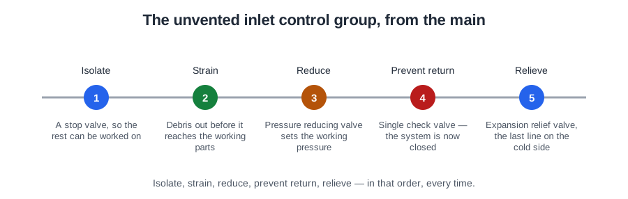
The order, from the main
- Isolating (servicing) valve
- Line strainer
- Pressure reducing valve
- Single check valve
- Expansion vessel connection
- Expansion relief valve
Learn it as a sentence: isolate, strain, reduce, prevent return, relieve. The balanced cold connection is taken off between the reducing valve and the check valve.
Why each one is where it is
The isolating valve comes first, on the cold supply close to the vessel but before any other control, so everything downstream can be worked on. Every service visit for the life of that cylinder starts by closing it.
The line strainer protects the reducing valve. It sits immediately before it because a reducing valve is a precise device: a single piece of grit on its seat makes it pass, hunt or stick. Put the strainer after the reducing valve and you have protected nothing that needed protecting.
Two things worth recognising about it. The signature of a blocked strainer is a burst of flow followed by weak flow — the stored volume comes out at pressure, then the system can only refill as fast as the blockage allows. And omitting a strainer is a functional problem, not a safety one: it costs a pressure reducing valve, but nobody is hurt.
The pressure reducing valve sets the working pressure the rest of the system is set against. It is drop tight, holding a steady outlet pressure under flow and no-flow alike, so downstream pressure cannot creep up when the taps are shut. It is set and sealed at the factory. Its cartridge can be replaced without changing the body.
The setting depends on the vessel, and the two are not interchangeable. A modern stainless steel cylinder is usually pre-set at about 3 to 3.5 bar, with the expansion valve above it at 6 bar and the T&P valve above both at about 7 bar — each stage set higher than the last. A copper vessel is weaker, so it takes a close-control reducing valve at 1 to 1.5 bar; a stainless unit is strong enough for a coarser pressure-limiting valve around 5 bar. Fit a limiting valve to a copper cylinder during a repair and the store is left well above its intended setting. Always confirm the figures on the data plate of the cylinder in front of you.
The check valve closes the system. It stops hot or warm water being pressurised back into the cold supply, which would be a fluid category 2 contamination — exactly the risk a single check valve is rated for. And it does something less obvious: by closing the only route back to the main, it makes the expanded water have nowhere to go. The check valve is the component that makes the expansion vessel necessary in the first place.
Expansion
Water expands by about 2 per cent from cold main temperature to storage temperature (about 4 per cent all the way to 100 °C) — small as a proportion, and considerable in a 210 litre cylinder whose way back to the main has just been closed.
An expansion vessel is a sealed vessel divided by a bladder, with a charge of air or nitrogen behind it. Boyle's law: a gas can be compressed, a liquid cannot. As the water expands it compresses the gas, and the system pressure rises only as far as the vessel was sized to allow.
Two types exist and only one is right here. The bladder (bag) type holds the water inside a neoprene bag so it never touches the steel — this is the type for unvented hot water. The diaphragm type, where the water lies against the steel, is for sealed heating systems where the water has been de-oxygenated by inhibitor, and must not be used on an unvented hot water system, where the water is always oxygenated.
The vessel goes on the cold inlet side, as close to the cylinder as possible and preferably higher, arranged to be self-draining. Cold side, because rubber at 12 °C lasts far longer than rubber at 60 °C, and because scale precipitates out of hot water rather than cold. Fit one on the hot side and it works — but not for long, and the failure looks like something else: the relief valve begins to weep on every reheat.
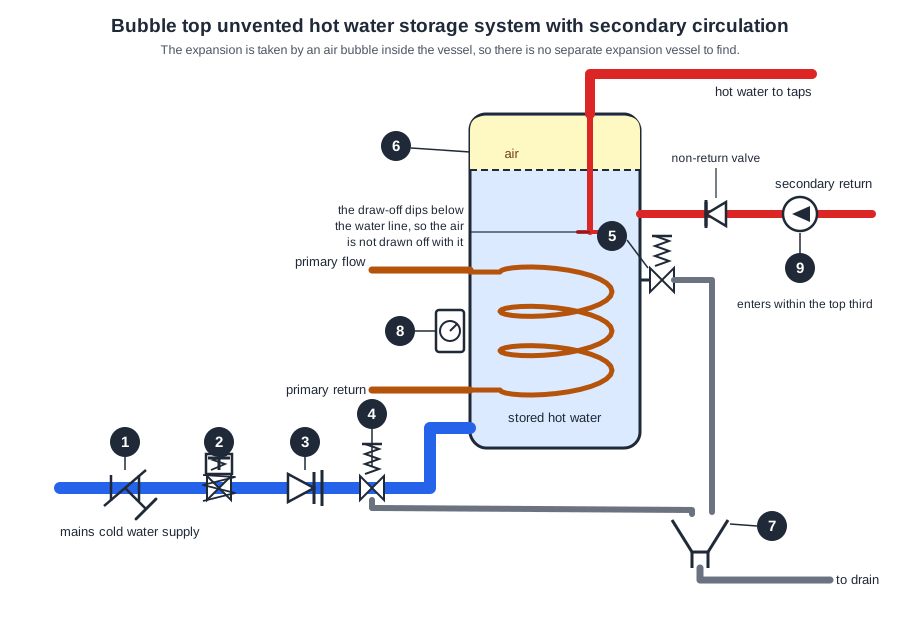
The alternative is internal expansion, the "bubble top" cylinder. An air pocket forms at the top of the vessel with a floating baffle plate between air and water. Over time the air is absorbed into the water and the pocket disappears, so the relief valve starts to discharge while the cylinder is heating and stops when it is up to temperature. The cure is to drain the cylinder right down and refill it to recharge the bubble — annually, or when the symptom appears.
The expansion relief valve
The expansion relief valve is the backup if the expansion device fails, or if the mains pressure becomes excessive. It is set above the reducing valve so that in normal operation it never opens: typically about 4 bar on a copper vessel and 6 bar on a stainless one.
Schedule 2 paragraph 22 governs it: it must close automatically after a discharge; be fitted on the supply pipe close to the vessel with no intervening valves; and only discharge at a pressure at least 0.5 bar (50 kPa) above the pressure the vessel normally sees.
Note where it sits: it is listed with the functional controls on the cold inlet, but its job is safety. It opens only if the expansion vessel or the pressure reducing valve fails, to let out excess pressure. It is not one of the two safety devices Approved Document G requires, which are the energy cut-out and the temperature relief valve. That makes it a very good witness. If an expansion valve is discharging on every reheat, something upstream has already failed. Check in this order:
- Confirm the pressure on the outlet side of the reducing valve is correct.
- Suspect a ruptured expansion vessel diaphragm, or a lost air bubble.
- In a hard water area, suspect calcium carbonate scaling the seat and spring, so the valve weeps or sticks.
The balanced cold connection
A mixer can only hold a blend if hot and cold arrive at comparable pressures. On an unvented system that is easy: take the cold supply to the outlets from the inlet group, after the pressure reducing valve and before the single check valve. Both sides then see the same reduced pressure, and the check valve stops the pressurised hot side pushing back into the cold branch.
Get it wrong and the fault is familiar: a new TMV, and the shower goes cold whenever a tap is run elsewhere. The valve is not faulty — the cold has been taken upstream of the reducing valve, so it swings with the main while the hot side stays steady. It is cheap to get right at first fix and expensive afterwards, because the cold branch is usually buried by the time anyone notices.
Composite valves, vacuum relief and anti-legionella valves
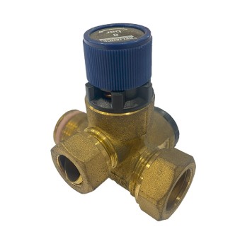
A cylinder fitted in the 1990s has five separate fittings in a row. One fitted last year has a single brass body with three connections. The components have not gone away — a composite valve contains the functional controls of the inlet group in one body, in the correct order: strainer, reducing or limiting valve, balanced cold take-off, single check valve, and expansion relief valve. The point is that there is no way to fit them in the wrong order, because the order is cast into the body.
A vacuum (anti-vacuum) relief valve exists because a cylinder built to resist pressure from the inside is far weaker against pressure from the outside. It lets air in when the internal pressure falls below atmospheric. Two conditions create the vacuum: water drawn off faster than it can be replaced, and the contents cooling and contracting — in both cases the check valve prevents anything flowing back in to fill the space.
The same physics explains a job you do by hand: a sealed vessel will not drain against a vacuum, which is why draining an unvented cylinder begins by opening a hot tap to let air in at the top.
An anti-legionella valve is fitted on the connection to the expansion vessel, and arranges the flow so the vessel's contents are exchanged every time water is drawn. An expansion vessel on the cold inlet is, in water terms, a dead leg: its contents sit still and warm gently in the airing cupboard. Nothing stands still, so nothing stagnates.
Two more requirements protect the water rather than the person: the vessel must be of an approved material — copper, duplex stainless steel, or lined steel — and where a vessel needs it, a sacrificial anode is fitted.
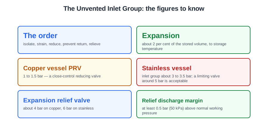
🔢 The numbers worth memorising
- The order
- isolate, strain, reduce, prevent return, relieve
- Expansion
- about 2 per cent of the stored volume, to storage temperature
- Copper vessel PRV
- 1 to 1.5 bar — a close-control reducing valve
- Stainless vessel
- inlet group about 3 to 3.5 bar; a limiting valve around 5 bar is acceptable
- Expansion relief valve
- about 4 bar on copper, 6 bar on stainless
- Relief discharge margin
- at least 0.5 bar (50 kPa) above normal working pressure
- Balanced cold
- taken after the PRV, before the check valve
- Vessel type
- bladder (bag) — never the diaphragm type used on sealed heating
⚠️ Where people go wrong
- Fitting the strainer after the pressure reducing valve. It then protects nothing that needed protecting.
- Using a heating-system diaphragm expansion vessel on unvented hot water. The water is oxygenated — it needs a bladder type.
- Fitting the expansion vessel on the hot side. It works, briefly, and then the relief valve weeps on every reheat.
- Fitting a coarse pressure-limiting valve to a copper cylinder. Copper is the weaker vessel — it needs close control at 1 to 1.5 bar.
- Taking the balanced cold upstream of the PRV. The shower then goes cold every time another tap runs, and the TMV gets blamed.
- Counting the expansion relief valve as one of the two safety devices Approved Document G requires. It is listed with the functional controls, although its job is safety — and it is a very good witness.
- Draining an unvented cylinder without opening a hot tap first. It will not drain against a vacuum.
📝 10-Question Self-Test
Straight from the Level 3 course question bank. Click an option to see whether you got it right — the explanation appears instantly, and there is nothing to submit.
The temperature and pressure relief valve is the safety device whose outlet is the start of the discharge pipework. D1 is the short run from that valve to the tundish, and the tundish gives the air gap and the visible sign that the valve has lifted.
Trace heating - a self-regulating electric heating tape under the insulation - keeps the water in a long dead leg hot, so the outlet runs hot at once without a secondary return. A bronze circulator would need a return pipe to circulate through.
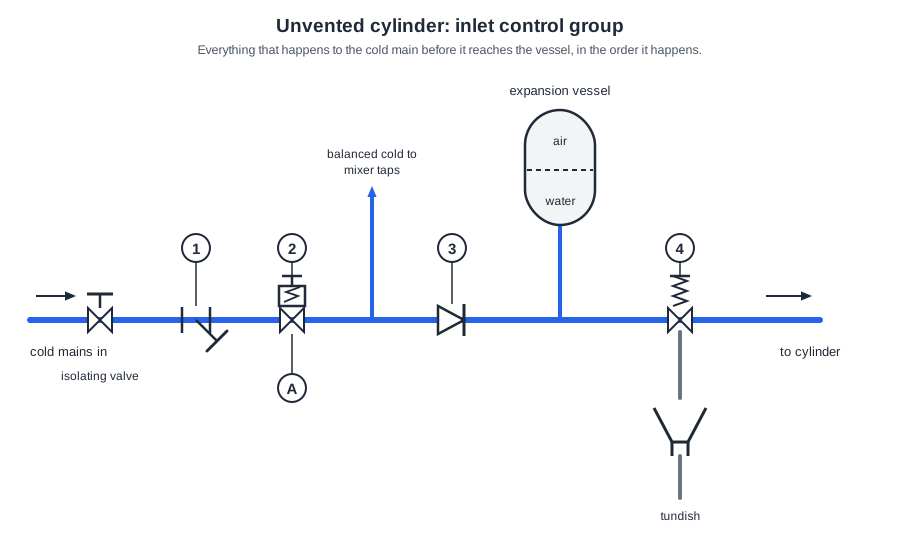
Number 4 is the expansion valve, last in the group after the expansion vessel tee, with its discharge dropping to the tundish. 1 is the line strainer, 2 the pressure reducing valve and 3 the single check valve.
Component 1 is the line strainer. Its mesh traps grit and debris from the main and protects the precise valves behind it, above all the pressure reducing valve immediately downstream. It gives no visible indication of flow: the component you look at to see whether anything has been discharging is the tundish, and that sits on the discharge side.
Component 6 is the expansion device. Water grows by about 2 per cent heating from mains temperature to 60 °C, and the single check valve has closed its route back to the main, so that volume has to be taken up, by a bladder vessel or by the air pocket in a bubble top cylinder. It stores nothing for the shower and warns of nothing.
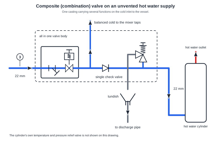
3 is on the run entering the valve body, ahead of the strainer, with the flow arrow pointing in and 22 mm marked against it, so it is the cold water inlet from the main. The grey pipe leaving the body lower down is the relief valve discharge to the tundish, which is what the “outlet connection to the expansion valve discharge” would mean.
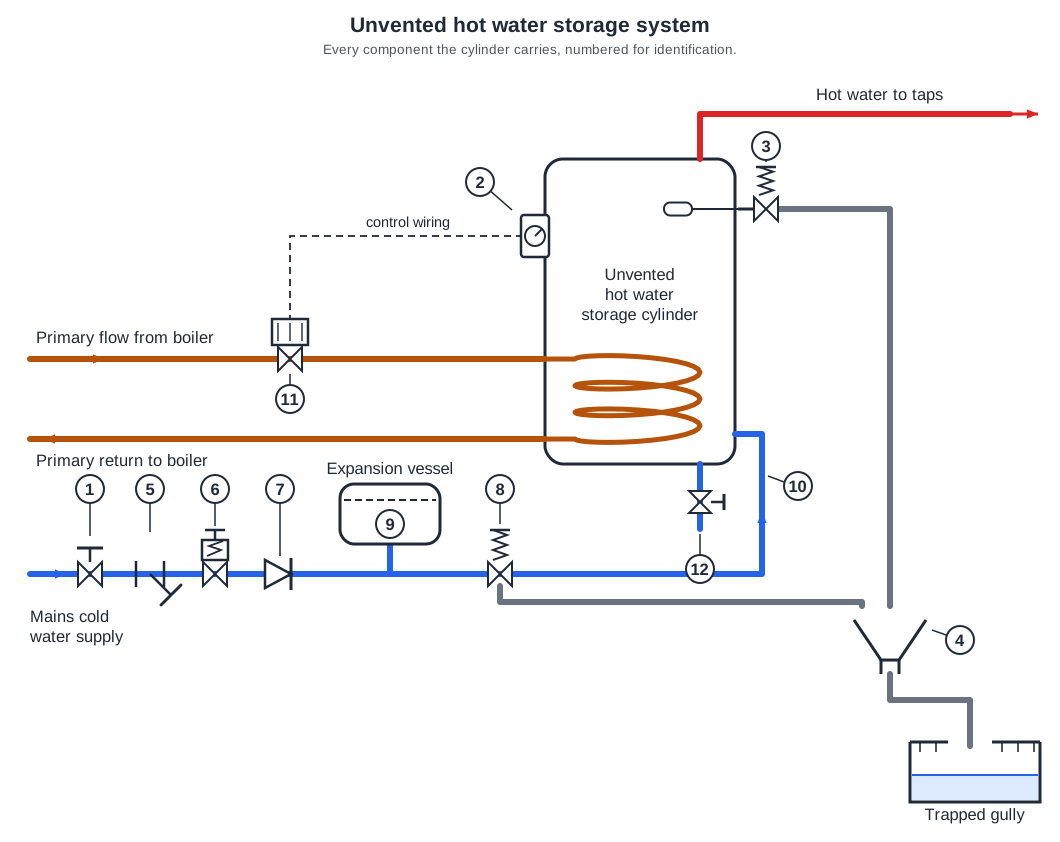
4 is the tundish, an open funnel with an air gap in the discharge pipe that both relief valves feed. Because it is open, water running through it can be seen, so a valve that is passing gives itself away instead of quietly dumping to the gully. Approved Document G 3.55 puts it plainly: any discharge should be visible at the tundish. It does no cooling.
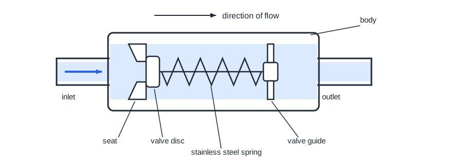
It is a single check valve. It stops hot or warm water from the pressurised cylinder being pushed back into the cold supply, which is a fluid category 2 contamination, water impaired by heat, taste or appearance. It does not take the expansion itself; the vessel does that, and the check valve is simply what makes a vessel necessary in the first place.
The combination valve is the inlet control group, and here that is 5, 6, 7 and 8: strainer, pressure reducing valve, single check valve and expansion relief valve in one body. “9, 10, 11 and 12” is the expansion vessel, the cold inlet, the motorised valve and the drain valve, four separate fittings scattered around the system.
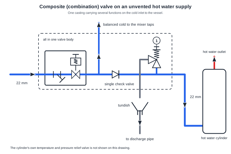
1 is a spring-loaded relief valve teed off the cold inlet, and its outlet is piped down to the tundish. It lifts on pressure alone, releasing the extra volume that heating creates once the check valve has stopped the water pushing back into the main. A “temperature relief valve” is a different device screwed into the cylinder itself, and the note says cylinder safety devices are not shown.
Going further: the lessons behind this article
This article is the public answer. Unit 332 of the Level 3 course takes the same ground to the depth the exam and the synoptic assignment ask for, in 3 lessons:
- The unvented inlet control group and its order
- Expansion on an unvented system: vessel, valve and balanced cold
- Composite valves, vacuum relief and anti-legionella valves
- Hot water systems: the Unit 332 guide — every article on this unit in one place
- All PlumbMate articles — Level 1, 2 and 3
- The Level 3 course — the whole 8202-35 Diploma