The cylinder is in, the pipework is clipped, and hot water comes out when you open a tap. A customer would call that finished. Approved Document G calls it static completion — and commissioning is everything that turns it into a system.
The short answer
Schedule 2 paragraph 13 of the Water Regulations is one sentence long: every water system shall be tested, flushed and where necessary disinfected before it is first used. Those three words are already in the right order.
The full sequence fills the gaps: visual inspection → fill and vent at normal operating pressure → soundness test → flush, and disinfect if needed → operational checks → commissioning record → handover.
Ask why the order matters and the answer is not that building control watch it in that order, or that a warranty specifies it. It is that each step depends on the state the step before it left the system in. You cannot pressure test pipework you have not looked at. You cannot flush a system you have not filled.
What commissioning actually means
Approved Document G paragraph 3.72 gives the definition worth learning. Commissioning is the advancement of a system from static completion to working order. For each system it includes:
- Setting to work.
- Regulation — testing and adjusting repeatedly until the system achieves the performance it was specified to achieve.
- The calibration, setting up and testing of the automatic controls.
- The recording of the performance test results that have been accepted as satisfactory.
That last item is as much part of the job as the first. A system that works but has no record has not been commissioned.
The four documents you work from
- The Water Supply (Water Fittings) Regulations 1999 — the legal minimum for testing, flushing and disinfection.
- BS EN 806, read with BS 8558 — the detailed procedures.
- Approved Document G3 — hot water safety, unvented systems, and notification of the work.
- The manufacturer's instructions — the appliance itself.
Two exam questions live in that last one. Where do you find the details for setting a water heater up so it achieves its specified output? The manufacturer's instructions — not the Building Regulations, not the layout drawing, not the contract programme. And where are the commissioning procedures for an unvented hot water storage system set out? Again, the manufacturer's instructions or specification. The standards tell you what has to be achieved; the manufacturer tells you how to achieve it on that appliance.
One idea runs underneath the whole of unvented commissioning. An unvented system has no open vent pipe, so every job the vent used to do — taking up expansion, capping the pressure, letting steam out — is now done by a device. Commissioning is where each of those devices is proved to work.
And the person who has to be told is the customer — not the Environment Agency, not the HSE, not Gas Safe. They are told twice: before commissioning begins, and again when it is complete.
The visual inspection
It is having a look round, but with a list, a drawing and a set of instructions in your hand — and it is the only stage of commissioning where a mistake costs nothing to put right. BS 5546 clause 8.1: before it is commissioned, the installation shall be inspected to confirm the work has been carried out as specified. You are reading the installation against the as-fitted drawing or specification, the manufacturer's instructions, and the regulations — not against your own opinion.
The walk round covers:
- Every open end capped off, every valve in the correct position.
- Every capillary joint soldered and every compression joint fully tightened.
- Enough clips, brackets and supports at correct spacings, all pipework secure.
- Equipment — cylinder, boosting pumps, expansion vessels, safety and functional controls — installed as the manufacturer requires, all unions tight.
- Unvented: expansion vessel pre-charge correct and matching the manufacturer's data.
- Vented: cisterns properly supported on sound timbers, float-operated valve provisionally set to the correct level.
- All appliance isolating valves and taps closed, ready to be opened one at a time when there is water in the system.
- D1 and D2 discharge pipework compliant, terminating somewhere safe but visible.
Below ground, BS 8000-15 clause 4.2 adds a rule with no exceptions: no part of a pipe trench is backfilled until the installation has been inspected. And clause 4.3 allows hydraulic pressure testing only after satisfactory visual inspection is complete.
The discharge arrangement, measured
This is the part learners most often get wrong, because it is judged on dimensions, not on looks. Approved Document G paragraph 3.54 requires the tundish to be vertical, in the same space as the cylinder, as close as possible to and lower than the safety device, with no more than 600 mm of pipe between the valve outlet and the tundish. That 600 mm length is D1.
So a tundish sitting in the same cupboard, below the valve, with 850 mm of D1 pipe is a defect. Being lower and in the same space are necessary, but not enough.
Do not confuse the figures. The 300 mm figure is the vertical section of D2 required below the tundish before any elbow, after which D2 falls continuously at at least 1 in 200 (paragraph 3.56). Paragraph 3.51 adds that D1 must be at least the nominal outlet size of the safety device.
Two controls that get confused
- The pressure reducing valve on the cold inlet sets and maintains the constant operating pressure in the system. Factory set and sealed; its outlet pressure stays constant while the mains fluctuates, and if the mains falls below the set pressure it simply stays fully open.
- The expansion relief valve (pressure relief valve) discharges water at a pre-determined pressure to prevent damage to the operational controls — protecting the system if the mains surges or the expansion device fails.
It is not the device that gives the visible warning — the tundish does that. Not the device that takes up expansion — the expansion vessel does that. And not the device that cuts the power on overheat — the energy cut-out does that.
Filling and venting
BS 8000-15 clause 4.5 is the rule to memorise: when the installation is complete, fill it slowly with the highest draw-off point open so that air is expelled, then inspect the installation, including all cisterns, tanks, cylinders and water heaters, for leaks.
Every part of that sentence is doing work. Slowly, because a fast fill traps air and risks water hammer. Highest point open, because air rises and has to leave somewhere — not the lowest drain valve, which wastes water without venting anything, and not every outlet closed, which is how you fill a system with air pockets.
BS EN 806-4 clause 6.1.1 allows only drinking water free of particles of 150 µm or larger — a mechanical filter to EN 13443-1, for example. That means fluid category 1 water direct from the main. Not softened, not de-ionised, and never dosed with inhibitor: inhibitor belongs in a closed heating circuit, not a potable hot water system.
On anything larger than a small dwelling, fill in stages, checking each for leaks before the next, so a fault is found while it is still easy to isolate.
- Vented: let the cistern fill to capacity and then open the gate valves, so the pipes run at full bore. Trickle filling encourages air locks, and an air lock formed during filling will still be there at handover.
- Unvented: check the expansion vessel pre-charge with a Bourdon pressure gauge before you fill, then fill with all the hot taps open. That stops pockets of high-pressure air being trapped in the top of the cylinder, which is what makes a newly filled unvented system splutter for days.
Draw water from every hot outlet in turn, closing each tap only when the water runs freely without spluttering. Let float-operated valves shut off and the pressure settle: the system is now at its normal operating pressure, which is the pressure at which the initial fill and leak check are always carried out.
The first step of the soundness test is then not to open anything and not to fit a gauge to the vent. It is to close all terminal fittings and inspect the pipework for leaks. A weeping joint found now costs a wipe; found under test pressure it costs a drain down.
Pneumatic testing — with air — is possible, but BS 8558 clause 5.1.9.1 does not recommend it because of the risk of explosion. Water is the default.
Draining an unvented cylinder
Schedule 2 paragraph 11 requires every system to be capable of being drained down. On an unvented cylinder the procedure catches people out because the vessel is sealed: close the cold supply servicing valve, open the drain valve or lowest hot outlet, and open the hot water taps so air can enter the cylinder. Without that air the cylinder holds a vacuum and will not empty. Opening the cold taps does nothing — they are on the other side of the cylinder.
Soundness testing: the Water Regulations tests
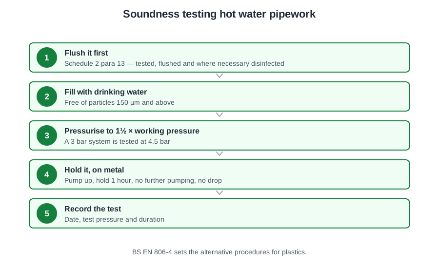
The pressure is applied deliberately higher than the system will ever see in service, so that a joint which would eventually weep fails now, in front of you, instead of in six months behind a boarded ceiling.
Schedule 2 paragraph 12(1): the system shall withstand an internal water pressure of not less than 1½ times the maximum pressure the installation is designed to be subjected to in operation. So an unvented system working at 3 bar is tested at 4.5 bar. Not 1¼ times, not 2½ times, and not simply whatever the incoming main gives you that day.
Metal systems (paragraph 12(2)(a)) — no plastics pipe anywhere. Subject the whole system to the test pressure by pumping, then continue for one hour without further pumping, with the pressure maintained and no visible leakage. One hour, no top-ups, no drop.
Plastics behave differently. Under pressure the pipe stretches, so the volume grows and the gauge falls — without a drop of water having escaped. A test demanding a flat line for an hour would fail perfectly sound pipework. So paragraph 12(2)(b) gives two alternative tests, and passing either is enough:
- Test A: test pressure by pumping for 30 minutes; reduce to one third of the test pressure; the pressure does not drop below one third over the following 90 minutes; no visible leakage. Bleeding down to a third lets the stretched pipe relax — if it is sound the pressure now holds or rises as the plastic recovers.
- Test B: test pressure by pumping for 30 minutes, note the pressure, then continue for 150 minutes without further pumping. The drop must be less than 0.6 bar (60 kPa) after the following 30 minutes, or 0.8 bar (80 kPa) after the following 150 minutes; no visible leakage.
One more figure, from BS 8000-15 clause 4.5: pipework and fittings that are not readily accessible must withstand twice the maximum working pressure. That is why concealed work gets an interim test of its own before it is boxed in.
Soundness testing to BS EN 806-4
Two rule books cover the same job and give different numbers. Read the question, see which one it names, and answer with that one's figures.
BS EN 806-4 works from maximum design pressure (MDP), not working pressure, and the multiplier is much lower:
TP = 1.1 × MDP
So a copper system with an MDP of 6 bar is tested at 6.6 bar. Where the equilibrium temperature of a plastics system is above 25 °C, a temperature derating factor fT from the pipe manufacturer is applied too: TP = 1.1 × fT × MDP. Do not carry 1.5 times across from the Water Regulations, and do not carry 1.1 times back the other way.
Clause 6.1.1 is exact about the equipment: the gauge and any recorder must have an accuracy of 0.02 MPa (0.2 bar), a range of 0 to 16 bar, and must be fitted at the lowest point in the system, where the static head is greatest. Not the highest point, not wherever the pump happens to be. (The old ±0.5 bar figure belongs to the withdrawn BS 6700.) A complete record of the test, including the test procedure diagram, must be made and preserved.
Choosing the procedure
| Material | Procedure |
|---|---|
| Linear elastic materials (metals) | A |
| Elastic, multilayer and visco-elastic up to DN/OD 63 | B or C |
| Visco-elastic over DN/OD 63 | B or C |
| Combined metal and plastics up to DN/OD 63 | A |
| Combined metal and plastics over DN/OD 63 | B or C |
Clause 6.1.3.4 says it again in words: installations comprising both plastics and metal pipes shall be tested to procedure A or procedure B. So a school with copper and PE-X gets A or B — not C, and certainly not a separate procedure for each material. Procedure C is for sections of an installation.
- Procedure A (metals). Vent, fill, seal the air vents and outlet valves, apply TP by pumping for 10 minutes. The pressure must stay constant — a drop of zero. Where ambient and water temperatures differ by more than 10 K, a 30 minute equilibrium period is allowed first. A 6 bar copper system: 6.6 bar held for 10 minutes with no drop.
- Procedure B (plastics). TP by pumping for 30 minutes, inspect for obvious leaks, then bleed to 0.5 times the test pressure and close the bleed valve. Leak-tight if the pressure holds at or above that for 30 minutes.
- Procedure C (plastics, and sections). TP by pumping for 30 minutes and note the pressure. Note it again after a further 30 minutes: a drop of less than 0.6 bar means no obvious leakage, and the test continues without pumping. Then watch for 2 hours: a drop of more than 0.2 bar in that period indicates a leak.
Work an example. A polybutylene system falls 0.4 bar between the 30 and 60 minute readings — under 0.6, so it passes that stage. It then falls a further 0.3 bar over the following two hours. That exceeds 0.2 bar, so it fails and the leak has to be found. Plastics expansion does not excuse it: the two-hour window exists precisely because the expansion has already happened.
Flushing
Cut open a brand new hot water system and you will find swarf, solder and flux residue, shreds of PTFE, jointing compound and building dust. Leave it there and it blocks strainers, jams thermostatic mixing valves, feeds bacteria, and — where flux is involved — corrodes the pipe and can push the copper content of the water above the drinking water limit.
BS EN 806-4 clause 6.2.1: the installation shall be flushed with drinking water as soon as possible after installation and pressure testing and immediately before commissioning. If someone asks which document sets out how a new cylinder and its pipework should be flushed, the answer is BS EN 806 — not Approved Document L, not BS 7671, not BS 5449.
The fluid is wholesome water, again free of particles of 150 µm and above. And one rule that is easy to forget: cold and hot water pipes are flushed separately.
The sequence
Before you start, protect the vulnerable parts: remove aerators, flow straighteners, flow regulators and shower heads to increase the flow, and shield WC flushing valves and thermostatic mixers from debris. Fixed filters upstream of valves are backwashed or renewed after flushing.
Then open every servicing valve in the section fully. In a multi-storey building the direction matters: flushing commences at the lowest storey and proceeds upward storey by storey. On each floor, draw-off points are opened starting with the point most remote from the riser, and closed again starting with the point at the upstream end.
The targets are a minimum velocity of 2 m/s and a change of the water in the system at least 20 times. Where flux residues will not shift, the standard notes it may be necessary to flush with warm water. Clause 6.2.3 offers an alternative using an intermittent drinking water and air mixture, at a minimum velocity of 0.5 m/s, with no flushing section longer than 100 m.
Unvented systems: the strainer first
The first stage of flushing a newly installed unvented system is to remove the line strainer, flush through, refit it and then fill. The strainer keeps grit out of the pressure reducing valve; on a new main it will catch everything the flush is trying to shift, and a blocked strainer looks exactly like a system with a flow rate problem.
Do not instead remove the expansion vessel or the temperature relief valve — and do not simply run every hot tap at full temperature, because there is nothing hot to run yet.
Existing systems, and systems left standing
BS 8000-15 clause 4.7.1: in premises separately occupied as a private dwelling, where the pipes serve only that dwelling, thoroughly flush every new service, extension or modification with fresh water drawn direct from the mains immediately before it is taken into use. For all other premises, ask the water supplier about approved pre-commissioning cleaning procedures.
Filling a system and draining it again is not flushing — that only moves debris from one place to another. Every outlet is run until the water is completely clear and free of discoloration.
And a system not going into use straight away does not simply sit. BS EN 806-4 requires it to be flushed at regular intervals of up to 7 days; the withdrawn BS 6700 (clause 6.1.10.1) put the outside limit at 30 days, and said a system not flushed at those intervals must be disinfected before it is brought into use.
Flushing produces paperwork too: clause 6.2.2 requires a complete record of the procedure to be made, retained and handed over to the building owner.
Disinfection: when, and the figures
BS EN 806-4 clause 6.3.1: for single dwellings, and minor extensions or alterations in any premises, disinfection is not usually necessary — flushing is sufficient.
The older list, from the withdrawn BS 6700 (clause 6.1.10.2), of where disinfection does follow the flush:
- New installations, except private dwellings occupied by a single family.
- Where major extensions or alterations have been carried out.
- Where underground pipework has been installed (other than localised repairs or inserted junctions).
- Where contamination is suspected — sewage, drainage, animals, or people entering a cistern to inspect, paint or repair it.
- Where a system has not been in regular use and not regularly flushed.
So a replacement cylinder in a family house, a new basin branch in a flat and a new outside tap all get flushing alone. A complete new hot and cold installation in a small hotel is neither a single dwelling nor a minor alteration, so it is disinfected.
Chemical: 50, one hour, 30
PD 855468 clause 8.5.1.1 gives the method (as the withdrawn BS 6700 clause 6.1.10.4.2 did). The system is filled with chlorinated water at an initial concentration of 50 mg/l (50 ppm) for a minimum contact period of one hour. At the end of that hour the free residual chlorine must be not less than 30 mg/l — a drop of no more than 40 per cent. If it is lower, the disinfection is repeated.
Work the case that catches people out. Dosed at 50 mg/l, one hour, residual measured at 22 mg/l. That is below 30, so the answer is repeat the disinfection — not extend the contact time, not accept it, and certainly not increase the dose to 100 mg/l. PD 855468 warns against exceeding 50 mg/l because of the corrosion risk to copper and the deterioration of non-metallic materials.
The contact period starts when the whole system, including cisterns filled to overflow level, holds solution at the initial concentration. The sequence is service pipes, supply pipes, cisterns, distributing pipes.
No part of the system is used during disinfection, and every outlet is marked DISINFECTION IN PROGRESS, DO NOT USE. No other chemicals — toilet cleaners especially — go into the water until the disinfectant is flushed out, because of the toxic fumes. All building users are told beforehand, including cleaners and security staff who work outside office hours. The water supplier is informed where pipework upstream of backflow protection is disinfected, and the sewerage authority's approval is obtained before chlorinated water goes to a drain.
Afterwards the system is immediately drained and thoroughly flushed until the free residual chlorine is back to the level in the incoming supply. Samples are then taken for bacteriological analysis; an unsatisfactory result means flush, re-disinfect and sample again. PD 855468 clause 8.3.4 advises taking microbiological samples two to seven days after treatment, because samples taken immediately can give false negatives.
Thermal disinfection
Hot water systems have a second option. PD 855468 clause 8.4.2: raise the temperature of the whole contents of the calorifier so the temperature at the hot outlets does not fall below 65 °C, and circulate for at least 1 hour. Then flush every hot outlet, running each tap and appliance sequentially for at least 5 minutes at 65 °C — not necessarily at full flow — and record the process.
Leaving the outlets closed pasteurises nothing: the dead legs are exactly where the bacteria are. And thermal disinfection can fail where part of the calorifier or system never reaches temperature for long enough.
🔢 The numbers worth memorising
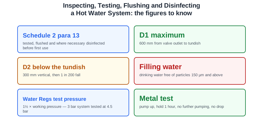
- Schedule 2 para 13
- tested, flushed and where necessary disinfected before first use
- D1 maximum
- 600 mm from valve outlet to tundish
- D2 below the tundish
- 300 mm vertical, then 1 in 200 fall
- Filling water
- drinking water free of particles 150 µm and above
- Water Regs test pressure
- 1½ × working pressure — 3 bar system tested at 4.5 bar
- Metal test
- pump up, hold 1 hour, no further pumping, no drop
- Plastics Test A
- 30 min, drop to one third, hold 90 min
- Plastics Test B
- 30 min, then <0.6 bar in 30 min or <0.8 bar over 150 min
- Concealed pipework
- twice maximum working pressure (BS 8000-15)
- BS EN 806-4 test pressure
- 1.1 × MDP — 6 bar MDP tested at 6.6 bar
- Gauge
- 0.2 bar accuracy, 0–16 bar, at the lowest point
- Procedure A
- 10 minutes, no drop
- Procedure B
- 30 min, bleed to half, hold 30 min
- Procedure C
- <0.6 bar in the next 30 min, then <0.2 bar over 2 hours
- Flushing velocity
- 2 m/s, water changed 20 times
- Air-and-water alternative
- 0.5 m/s, sections no longer than 100 m
- System left standing
- flush every 7 days; outside limit 30 days
- Chemical disinfection
- 50 mg/l, 1 hour, residual not below 30 mg/l
- Thermal disinfection
- outlets not below 65 °C, circulate 1 hour, run each outlet 5 min
- Sampling after treatment
- 2 to 7 days
⚠️ Where people go wrong
- Treating the record as paperwork after the job. Recording the results is part of the definition of commissioning.
- Shuffling the order. Each step depends on the state the one before it left the system in.
- Judging a tundish by looks. Same space and lower than the valve are necessary but not enough — 850 mm of D1 is a defect.
- Mixing up 600 mm and 300 mm. 600 is D1 to the tundish; 300 is vertical D2 below it.
- Filling from the lowest drain valve, or with every outlet closed. Highest draw-off open, filled slowly.
- Adding inhibitor, or using softened water, to fill a potable system.
- Opening the cold taps to drain an unvented cylinder. Open the hot taps — that is where air gets in.
- Carrying 1.5 × working pressure into a BS EN 806-4 test, or 1.1 × MDP into a Water Regulations one.
- Fitting the test gauge at the highest point. BS EN 806-4 puts it at the lowest.
- Giving a mixed copper-and-plastics system procedure C. It gets A or B.
- Passing a Procedure C test on the first 30-minute reading alone. The 2-hour, 0.2 bar stage still has to be met.
- Flushing hot and cold together, or flushing top-down in a multi-storey building.
- Leaving the line strainer in on a new unvented fill. A blocked strainer reads as a flow rate fault.
- Disinfecting a replacement cylinder in a family home. Single dwellings and minor alterations need flushing only.
- Increasing the chlorine dose, or extending the contact time, when the residual comes back at 22 mg/l. Repeat the disinfection.
- Thermally disinfecting with the outlets closed. The dead legs are where the bacteria are.
📝 10-Question Self-Test
Straight from the Level 3 course question bank. Click an option to see whether you got it right — the explanation appears instantly, and there is nothing to submit.
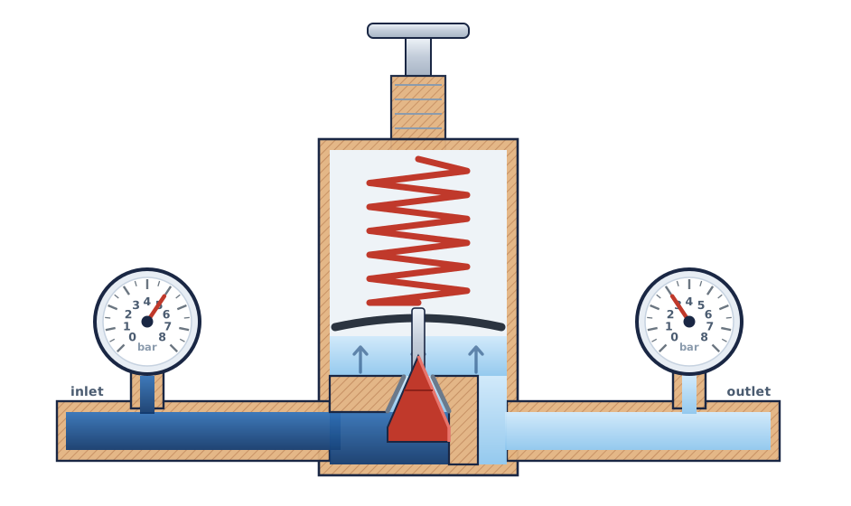
A pressure reducing valve is fitted on the cold inlet to bring a variable mains pressure down to the fixed working pressure the cylinder, its expansion vessel and its relief valve are all designed around, and to hold it there as the main rises and falls through the day. The nitrogen-charged chamber is the expansion vessel, the visible warning is the tundish, and the overheat cut-out is an electrical device.
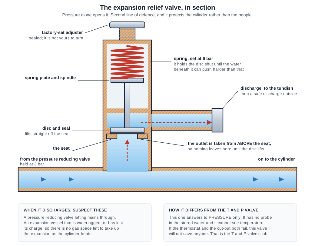
A spring loaded valve on the cold supply to the cylinder with no temperature sensing element, so it opens purely on pressure and dumps to the tundish before that pressure can damage the vessel or its controls. Schedule 2 paragraph 22(2) puts it close to the vessel, opening at least 0.5 bar above working pressure. Letting water “expand into a charged chamber” is the expansion vessel’s job.
Close the drains so the water stays in, open the hot taps so the air has somewhere to go, then let the mains in slowly, closing each tap as it runs without spluttering. Turning the mains on at full bore with the taps shut traps the air in the vessel and shocks the pipework, and opening the drain valves first just wastes the fill.
Hot water pipework and the storage vessel are tested hydraulically with water. BS EN 806-4 6.1.2 sets the test pressure at 1.1 times the maximum design pressure; the 1.5 times the working pressure that older material gives comes from BS 6700, which is withdrawn.
The system is already full and at normal working pressure, so the first move is simply to shut everything and walk the pipework looking for weeps before any test pressure is applied. Running every outlet until the water clears is flushing, which comes after testing, and draining the pipework undoes the fill you have just carefully carried out.
The installation is flushed with drinking water as soon as possible after installation and pressure testing, hot and cold separately, before commissioning.
BS EN 806-4 clause 6.2.1 is the flushing procedure: flush with drinking water as soon as possible after installation and pressure testing and immediately before commissioning, with hot and cold pipes flushed separately. Approved Document L covers energy efficiency, BS 7671 is electrical and BS 5449 dealt with forced circulation heating — none of them deals with flushing a hot water service.
BS 8000-15 clause 4.3 allows hydraulic pressure testing only once visual inspections are complete and satisfactory, and for good reason: you cannot test pipework you have not looked at, and a bad joint spotted dry costs a wipe rather than a drain down. Setting the cylinder thermostat, balancing and the commissioning checklist all come later, once the system has been proved to hold water.
You look first and prove it second. The inspection confirms the components are connected in the right order and the right way round; the test then shows those connections hold. Flushing and disinfection come after testing rather than instead of it, and interim testing precedes final testing on concealed work rather than following a performance test.
Everything after this involves heat, and finding a weeping joint after the cylinder is hot is a much worse afternoon.
Going further: the lessons behind this article
This article is the public answer. Unit 332 of the Level 3 course takes the same ground to the depth the exam and the synoptic assignment ask for, in 7 lessons:
- Commissioning: the documents and the running order
- The visual inspection before the system is filled
- Filling and venting at normal operating pressure
- Soundness testing: the Water Regulations tests
- Soundness testing to BS EN 806-4: procedures A, B and C
- Flushing hot and cold systems, and in what order
- Disinfection: when it is needed and the figures
- Hot water systems: the Unit 332 guide — every article on this unit in one place
- All PlumbMate articles — Level 1, 2 and 3
- The Level 3 course — the whole 8202-35 Diploma