The most common reason an unvented installation ends with an unhappy customer is not the cylinder. It is the main feeding it — and that is a measurement you take before you quote, not an assumption you make afterwards.
The short answer
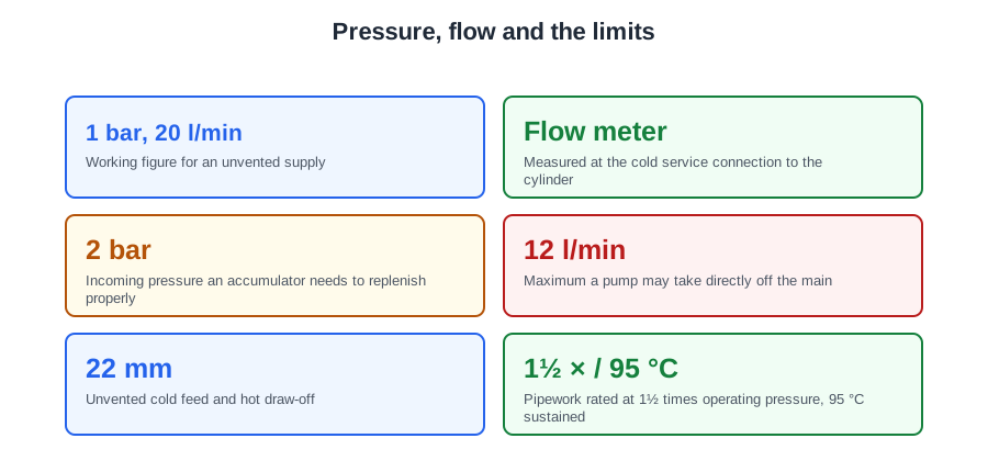
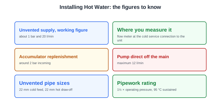
An unvented system needs pressure and flow, independently. As a working figure, look for about 1 bar and 20 litres per minute; the specific minimum for a given unit comes from the manufacturer's installation instructions. Confirm it with a flow meter at the cold water service connection to the unit — not at a garden tap on a different branch.
7.5 bar at 5 litres a minute is not a usable supply. Five litres a minute will not run a shower whatever the pressure, and 7.5 bar is above the maximum inlet pressure of most units anyway. That single example is the whole point: the two figures do not substitute for one another.
Then three installation rules carry most of the marks: hot water must reach the outlet above 50 °C within one minute, insulation is required beyond a table of lengths that tighten as the pipe gets bigger, and the discharge pipe D2 goes up one size for every 9 m of equivalent resistance.
Static and dynamic pressure
Pressure comes in two forms and only one of them is worth designing around.
- Static pressure is the pressure with nothing flowing. It is always the higher figure.
- Dynamic, or running, pressure is what you have with outlets open — and it falls at peak times.
A house showing 2 bar static may drop below 1 bar dynamic on a busy evening, which is the difference between a system that works and one you get called back to. Take the reading when the street is using water, not at ten in the morning when nobody is home.
When the supply is not good enough
Two remedies exist and they are often used together.
- A cold water accumulator stores water at mains pressure overnight, when pressure is highest, and gives it back during the day. It typically needs around 2 bar incoming to replenish properly.
- Where even that is not available, a booster pump goes ahead of it. A pump taking water directly from the undertaker's main must not deliver more than 12 litres per minute under the Water Supply (Water Fittings) Regulations.
On an accumulator installation two pressure reducing valves are usually fitted: the first controls the pressure entering the property, the second reduces it to the figure the cylinder manufacturer requires. A pressure reducing valve is the type in which back-pressure in the valve chamber acts across the full diaphragm to close it, which is what gives it close control of its outlet pressure.
The order of the inlet group
On an unvented unit the incoming order is examinable and it does not vary:
cold water supply → stop valve → in-line strainer → pressure reducing valve → single check valve → expansion vessel connection → expansion (pressure) relief valve → cylinder
The balanced cold connection is taken off after the pressure reducing valve, so that blended outlets see equal pressures on both sides. Take it off before the PRV and every shower in the house becomes a temperature fight.
Pipe sizes, materials and routing
Sizes are set by what the vessel needs. Unvented systems normally need at least a 22 mm cold feed from the undertaker's supply, because of the flow rate they work at, and a 22 mm hot draw-off, reduced for individual appliances such as basins, sinks and bidets.
Materials are copper to BS EN 1057 or polybutylene. The pipework must withstand at least 1½ times the normal operating pressure and sustained temperatures of 95 °C with occasional excursions to 100 °C.
Route the pipes so hot pipework does not warm cold pipework running alongside it — the Water Regulations require cold water not to be warmed above 25 °C so far as is reasonably practicable. And allow for expansion where pipes pass through walls and floors, or the installation will tick and creak: polybutylene expands about 0.00018 m per metre per degree, copper about 0.000016 m.
The electrical connection, and proving the work
The final connection to an immersion heater is made in heat resistant flexible cable. Size the protective device from the load: a 6 kW heater on 230 V draws about 26 A, so a 32 A Type B circuit breaker is the suitable rating.
Soundness is proved by a hydraulic test with water at 1.5 times the maximum working pressure — not an air test. Take care not to exceed the pressure an open vented cylinder can stand; if necessary disconnect it and cap the pipework before testing.
Dead legs, and the one-minute rule
A customer in a long bungalow runs the en suite basin tap for half a minute before anything warm arrives. That is a dead leg: cold water standing in a hot pipe between uses, run to waste every time. It is a fault of design, and there are only two remedies.
BS 8558 clause 4.3.5.1.1 says hot water should reach the outlet at or above 50 °C within one minute of running the water, and the same applies to the supply feeding a thermostatic mixing valve. That one figure limits dead leg length and pipe size at once, because an oversized draw-off holds more cool water per metre that has to be run off first.
Dead legs should be insulated and as short as practicable, and on a secondary circulation system a dead leg should not exceed a volume of 0.5 litres.
Which pipes must be insulated
The guidance to the Water Regulations requires, as the withdrawn BS 6700 (clause 5.9.3.1) did, that hot pipes to a tap longer than the lengths below are insulated — and that all fittings forming part of a primary or secondary circulation system are insulated whatever their length.
| Outside diameter | Maximum uninsulated length |
|---|---|
| 12 mm | 20 m |
| Over 12 up to 22 mm | 12 m |
| Over 22 up to 28 mm | 8 m |
| Over 28 mm | 3 m |
The limit tightens as the pipe gets bigger, because a bigger pipe holds more standing water per metre — so it earns fewer metres. Note the sizes are outside diameters.
The compliance guidance under Part L adds the practical rules: primary circulation pipes for domestic hot water are insulated throughout their length; all pipes connected to a hot water storage vessel — including the vent pipe — are insulated for at least 1 metre from the vessel or to where they become concealed; and where secondary circulation is used, all pipes kept hot by it are insulated.
Besides saving energy, insulation keeps the distribution above 50 °C at the outlets and the return at 50 °C or more (55 °C in healthcare). It is a legionella control measure as much as an efficiency one — which is the version of the argument that persuades a customer unmoved by pence.
When a secondary loop is justified
A secondary circulation loop is justified where the run is too long for the dead leg limits, or where the 50 °C-in-a-minute figure cannot otherwise be met. It is not free: a pump runs, a circuit loses heat continuously, and the return must come back at 50 °C or more (55 °C in healthcare). The withdrawn BS 6700 (clause 5.3.8) put it bluntly, and it still holds — secondary circuits inevitably dissipate heat and should be avoided where they can be.
Installing it:
- The pump must have a bronze or stainless steel body, because it carries potable water. A cast iron central heating circulator would rust and discolour the supply, and must never be used.
- Open vented: the return enters the cylinder about a quarter of the way down, pump on the return close to the vessel, with a single check valve between pump and cylinder to prevent reverse circulation.
- Unvented: there is usually no secondary connection on the vessel, so the return goes into the cold feed through a swept tee just before the unit, again with a check valve after the pump.
- Control it on a time clock with pipe thermostats, so the pump is not running twenty-four hours a day.
The alternative to a loop altogether is electric self-regulating trace heating under the insulation, maintaining at least 50 °C and removing the dead leg without a return pipe.
The four temperatures
Four numbers run through every hot water system. Only the bath limit is regulation, in Approved Document G; the other three are HSG274 Part 2 and BS 8558 guidance, and you work to all four:
- Store at 60 °C.
- Deliver above 50 °C at the outlets within one minute.
- Bring a secondary return back at 50 °C or more (55 °C in healthcare).
- Limit the supply to a bath to a maximum of 48 °C.
The logic is a chain: store hot enough to be safe from bacteria, distribute hot enough to stay that way, deliver cool enough to be safe from scalding. The first two come from legionella control; the third from Approved Document G paragraph 3.65, which limits hot water supply to a bath to 48 °C by an in-line blending valve or other temperature control device with a maximum temperature stop.
The device that reconciles them is the thermostatic mixing valve — and understand exactly what it does. It protects against scalding. It does nothing about bacteria. Keeping the store hot is what controls the bacteria; the valve simply makes the delivered water safe to touch. Where communal showers serve schools or the public, the Water Regulations guidance puts the discharge limit at 43 °C.
Controlling the stored temperature, in tiers
Stored water must never exceed 100 °C. Three devices operate in order as the temperature rises:
- A thermostat set to the working temperature. On a cylinder heated directly by an immersion heater, the immersion's own thermostat is the component that controls the temperature of the hot water — typically adjustable between 50 and 70 °C.
- A second, high limit thermostat or energy cut-out, independent of the first, which cuts the supply if the working thermostat fails. Manually resettable, or non-resettable and requiring the heater to be replaced.
- On an unvented vessel, a temperature and pressure relief valve as the last line, fitted directly on the vessel so stored water cannot exceed 100 °C.
Sizing the discharge pipework
An unvented unit carries an expansion (pressure) relief valve and a temperature and pressure relief valve. Both discharge through a short metal pipe, D1, into a tundish.
The tundish is vertical, in the same space as the cylinder, within 600 mm of the valve outlet, and it exists so a discharge from either valve is visible. D1 must be at least the nominal outlet size of the safety device.
From the tundish, D2 falls to a safe outside termination, with 300 mm vertical below the tundish before any bend and then a continuous fall of at least 1 in 200. Its size comes from Approved Document G Table 1:
| Minimum D1 | D2 size | Maximum straight length |
|---|---|---|
| 15 mm | 22 mm | 9 m |
| 15 mm | 28 mm | 18 m |
| 15 mm | 35 mm | 27 m |
The rule underneath the table: D2 is one size larger than the valve outlet for up to 9 m of equivalent resistance, two sizes for 9 to 18 m, three sizes for 18 to 27 m, and so on. Bends count: each 22 mm elbow is 0.8 m, each 28 mm elbow 1.0 m.
Worked example
A G½ valve with a 15 mm D1, and a D2 run of 7 m with four 22 mm elbows.
- In 22 mm the allowance is 9 m, less 4 × 0.8 = 3.2 m, leaving 5.8 m. Not enough for 7 m.
- Go up a size. In 28 mm the allowance is 18 m, less 4 × 1.0 = 4 m, leaving 14 m.
A 28 mm D2 is satisfactory. Notice the elbow allowance changes with the pipe size — work it in the size you are testing, not the size you started with.
One practical rule to close on. If an expansion vessel fails and a replacement has to be ordered, isolate the system and temporarily decommission it so it cannot be used until the vessel is replaced; where pipework is left open, cap the ends off.
🔢 The numbers worth memorising
- Unvented supply, working figure
- about 1 bar and 20 l/min
- Where you measure it
- flow meter at the cold service connection to the unit
- Accumulator replenishment
- around 2 bar incoming
- Pump direct off the main
- maximum 12 l/min
- Unvented pipe sizes
- 22 mm cold feed, 22 mm hot draw-off
- Pipework rating
- 1½ × operating pressure, 95 °C sustained
- Cold water not warmed above
- 25 °C
- 6 kW immersion on 230 V
- about 26 A — a 32 A Type B breaker
- Soundness test
- hydraulic, 1.5 × maximum working pressure
- Hot at the outlet
- above 50 °C within one minute
- Uninsulated hot pipe (OD)
- 12 mm 20 m, 22 mm 12 m, 28 mm 8 m, over 28 mm 3 m
- Pipes at a storage vessel
- insulated 1 m from the vessel, vent pipe included
- Dead leg on a secondary system
- no more than 0.5 litres
- The four temperatures
- store 60, outlet 50+, return 55, bath 48 °C max
- Communal shower discharge
- 43 °C
- Tundish
- vertical, same space, within 600 mm of the valve
- D2 fall
- 300 mm vertical before any bend, then 1 in 200
- D2 sizing
- one size per 9 m of equivalent resistance
- Elbow allowance
- 0.8 m at 22 mm, 1.0 m at 28 mm
⚠️ Where people go wrong
- Reading pressure and assuming flow. 7.5 bar at 5 l/min is unusable — the two figures never substitute for one another.
- Taking the reading at a garden tap, or at ten in the morning. Measure at the unit’s own connection, at peak.
- Quoting static pressure as the design figure. Dynamic is what the system actually gets.
- Taking the balanced cold before the pressure reducing valve. Every blended outlet then fights itself.
- Air-testing an unvented installation. Soundness is hydraulic, at 1.5 × working pressure.
- Reading the insulation table as inside diameter. The lengths are by outside diameter.
- Assuming a short pipe on a circulation system escapes insulation. On a primary or secondary circuit, every fitting is insulated whatever its length.
- Fitting a cast iron circulator to a secondary loop. It carries potable water — bronze or stainless only.
- Believing a TMV controls legionella. It protects against scalding and nothing else.
- Sizing D2 off straight length alone. Each bend eats 0.8 or 1.0 m, and the allowance changes with the size you are testing.
📝 10-Question Self-Test
Straight from the Level 3 course question bank. Click an option to see whether you got it right — the explanation appears instantly, and there is nothing to submit.
Approved Document G Table 1: from a temperature relief valve with a 15 mm minimum D1, a 22 mm D2 is allowed up to 9 m, a 28 mm up to 18 m and a 35 mm up to 27 m. Those are straight-run figures, and each 28 mm elbow takes another 1.0 m off the allowance. 9 m is the figure for 22 mm, not for 28 mm.
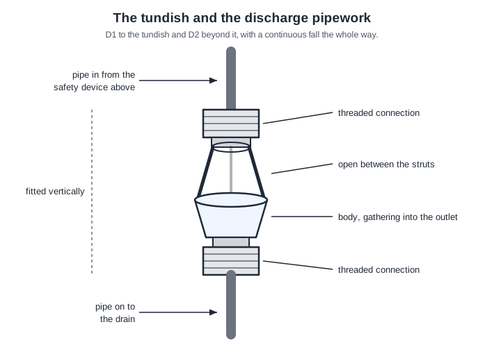
The tundish is an open air break in the discharge pipe, so anything coming from either relief valve is seen. Approved Document G 3.54 puts it vertical, in the same space as the cylinder and no more than 600 mm from the valve outlet, and 3.55 requires the discharge to be visible. It does not cool the water, collect scale or give rodding access.
Approved Document G Table 1: with a 15 mm minimum D1, a 22 mm D2 is permitted up to 9 m of straight pipe, a 28 mm up to 18 m and a 35 mm up to 27 m. 18 m is the 28 mm figure, which is the one most learners reach for. Bends come off the allowance too — each 22 mm elbow counts as 0.8 m.
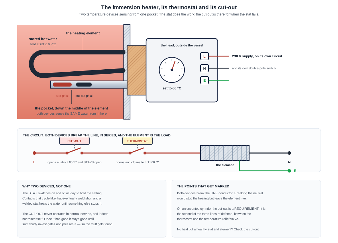
The probe sits in the stored water alongside the element, the dial is marked in °C, and the live and neutral of the 230 V supply run through the switch. It breaks the supply to that element once the water reaches the set temperature. Switching “the boiler on and off” is the job of a cylinder thermostat strapped to the outside of the vessel.
In a pressure reducing valve the outlet pressure is fed back into the valve chamber and acts across the whole area of the diaphragm, so the valve throttles in proportion to what is happening downstream. That feedback is what gives close control of the set outlet pressure. A double check valve is a backflow device and a servicing valve is simply open or shut; neither modulates anything.
Copper expands as hot water passes and contracts as it cools. Where a pipe is tight in a joist notch with no sleeve or packing, that movement rubs and creaks. It is a fixing problem, not an air lock.
Twelve metres. The figures come from Table 7 of the withdrawn BS 6700, "Maximum recommended lengths of uninsulated hot water pipes", graded by outside diameter: up to 12 mm, 20 m; over 12 up to and including 22 mm, 12 m; over 22 up to and including 28 mm, 8 m; over 28 mm, 3 m. Be clear about their standing, because it is unusual. BS 6700 was withdrawn on 1 August 2012 and nothing has taken the table on: the word "uninsulated" does not appear in BS 8558 at all, BS EN 806 gives no lengths, the Water Regulations Guidance has no table of them, and there is none anywhere in the Building Regulations either. So these are the figures the trade still works to and the ones you will be examined on, but they are recommendations from a withdrawn standard rather than a current requirement, and you should not cite them as a rule. What has not changed is the reason behind them: every metre of uninsulated dead leg is water that goes cold between draw-offs and is run to waste before the hot arrives.
An unvented cylinder needs flow as well as pressure; 5 litres a minute will not fill a bath or run a shower whatever the pressure. High incoming pressure is not the objection: the maximum working pressure is the one the maker states, and a pressure reducing valve brings the supply down to it.
Pipes are sized so that the last outlet on the run still gets the flow it needs at a usable pressure once friction has taken its toll. Velocity limits are a constraint on that, not the aim: holding every pipe below 0.5 m/s would mean oversizing everything, and on hot water an oversized draw-off just holds more cool water to run off before hot arrives.
BS EN 806-2 clause 19.2.7 gives the height on a gravity circulation system as not less than 150 mm plus 40 mm for every metre from the cistern overflow level to the lowest point of the cold feed; the withdrawn BS 6700 5.3.9.2 has the same words. The head is what pushes water up the vent, so the allowance grows with it. The fixed part is 150 mm, not 450 mm.
Going further: the lessons behind this article
This article is the public answer. Unit 332 of the Level 3 course takes the same ground to the depth the exam and the synoptic assignment ask for, in 3 lessons:
- Supply pressure and flow, and where the pipes run
- Insulation, dead legs and secondary circulation
- Temperature control, outlets and safety relief pipework
- Hot water systems: the Unit 332 guide — every article on this unit in one place
- All PlumbMate articles — Level 1, 2 and 3
- The Level 3 course — the whole 8202-35 Diploma