Three complaints, three different answers. The shower dribbles on a vented system. The unvented cylinder cannot be fitted because the main is weak. The pipework bangs every time a lever tap is shut.
The short answer
The valve bodies at an outlet are ordinary; the control on them is not. And three devices sit behind them — a pump for a system with no head, an accumulator for a main with no flow, and a shock arrestor for a system that has been closed by a check valve.
Automatic and self-closing taps
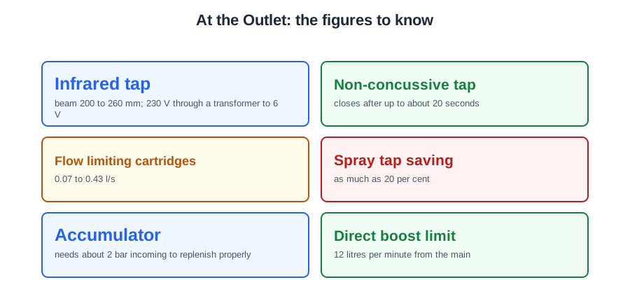
Infrared taps. The sensor eye emits a beam roughly 200 to 260 mm wide. A hand interrupting it sends an electronic signal to a solenoid valve, which snaps open and passes a restricted flow; when the hand leaves, the beam is restored and the valve closes. Power is usually 230 V through a transformer to 6 V, with a thermostatic blending valve behind the tap.
The advantages explain where they are used: easy to operate, they stop the spread of germs because nothing is touched, they conserve water, and they prevent scalding. For a nursing home, an infrared tap is the most hygienic option.
Non-concussive (self-closing) taps. Pressing the head works a spring-loaded plunger that opens the tap; the spring closes it after a set time, adjustable to about 20 seconds. Most use an internal cartridge, so maintenance is a cartridge change.
They save water and are largely vandal-proof, but the trade-offs matter and they are examined: the rapid closing causes water hammer, they need regular maintenance, they should not be used where grease or dirt can foul them, they scale up in hard water, and the small volume released may leave waste pipes below self-cleansing velocity.
Bath/shower mixers and the hose
Made as pillar, deck, thermostatic (with a temperature-sensitive wax cartridge) and wall mounted types. They are designed for equal hot and cold pressures and must not be fitted where the cold is straight off the main and the hot comes from a vented low pressure cylinder — the blend cannot be held, and the cold can push hot water back into the cylinder.
The hose is the backflow risk, because the head can lie in used bath water. Either fit double check valves on the hot and cold connections, or fix the hose with a retaining ring so the head cannot drop below the overspill level. Most modern mixers include a type HC diverter with automatic return as built-in protection.
Flow limiters and spray taps
A flow limiting valve holds the flow to an appliance at a set rate whatever the upstream pressure. Interchangeable cartridges give between 0.07 and 0.43 l/s, so one body suits basins, baths, sinks, bidets and WCs. They take the guesswork out of pipe and pump sizing, help balance hot and cold, and stop one appliance such as a shower taking all the available water.
A spray tap breaks the flow into a fine spray, cutting the water used at that tap by as much as 20 per cent. An aerator does something different: it introduces air so the flow appears fuller and softer.
And choose for the user as well as the building. For a customer with arthritis in their hands, a quarter turn lever tap is the right answer: it needs a push rather than a grip and repeated turning.
Two backflow points belong here. A kitchen sink is protected by an AUK3 tap gap — at least 20 mm, or twice the bore of the outlet — because a sink is fluid category 5. And an ascending spray bidet is also category 5, so it may only be fed from a low pressure system supplied from a storage cistern with the required air gap, never from the main or from a mains-fed unvented system.
Shower pumps
Two arrangements, and the distinction is where the pump sits relative to the mixing valve:
- Single impeller outlet pump — fitted after the mixing valve, boosting the already mixed water to the shower head. The same type boosts a single hot or cold outlet elsewhere.
- Twin impeller inlet pump — fitted before the mixing valve, boosting hot and cold separately, with one motor driving both impellers. With the right pump this can serve the whole house, and it has become the more common of the two — a single impeller pump is often difficult to install to the manufacturer's requirements after the valve.
Pump position, pipe sizes and the minimum head all come from the manufacturer's instructions. Where there is not enough head above the pump, a negative head pump is used, and the hot supply is usually taken from the top of the cylinder through an Essex flange so that air is not drawn in.
A safety point examiners like: if a shower pump develops a serious electrical overheating fault and the part has to be ordered, the pump is isolated and the system temporarily decommissioned so it cannot be used while you wait.
Accumulators
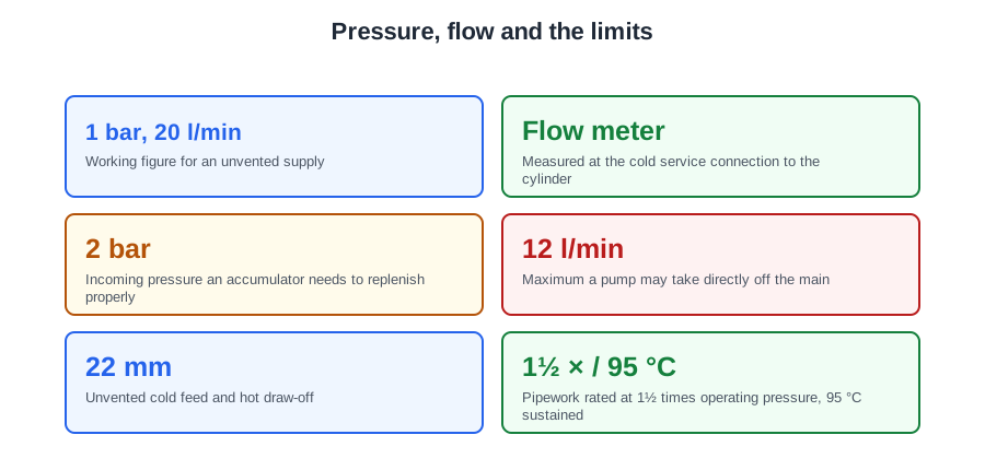
Where the incoming supply is weak, an accumulator increases the cold water pressure and flow available. It fills at night, when demand in the area is low and the main is at its highest pressure, and gives that water back through the day. That is the appliance to consider when an unvented cylinder is wanted in an area where the flow rate to dwellings is inadequate.
Three practical figures. An accumulator needs a minimum incoming pressure, usually around 2 bar, to replenish properly; below that a booster pump is added as well. A booster pump delivering more than 12 litres per minute directly from the main is not permitted. And the installation uses two pressure reducing valves: the first controls the pressure entering the property, the second reduces it to the figure the cylinder manufacturer requires.
Water hammer and shock arrestors
Water hammer is a pressure surge created when moving water is stopped suddenly. The shock wave travels back against the flow, and a system normally running at 3 bar can see surges of twice that, which loosens fittings, causes noise and eventually causes leaks.
A shock arrestor is made of corrosion resistant brass, copper or stainless steel and contains a piston or diaphragm cushioned by a calculated volume of inert gas. When the shock wave arrives the piston moves with it, absorbing the kinetic energy so the wave dissipates.
The classic places to fit one are exactly where a fast-closing tap meets a closed system: near a quarter turn tap with a single check valve fitted, or beside a lever operated mixer fed from mains pressure hot water with a check valve. The check valve is what makes the difference — it leaves the surge nowhere to go.
Some shock arrestors double as mini expansion vessels. On mains-fed hot water — an unvented cylinder, a combi, a multipoint — the small volume of water in the pipework still expands when heated, and the rising pressure damages shower mixing valves and backflow prevention devices. A mini expansion vessel gives that expansion somewhere to go, and most major shower manufacturers require one. The same fitting is used on cold pipework, where water standing in a warm room expands with nowhere to escape.
🔢 The numbers worth memorising
- Infrared tap
- beam 200 to 260 mm; 230 V through a transformer to 6 V
- Non-concussive tap
- closes after up to about 20 seconds
- Flow limiting cartridges
- 0.07 to 0.43 l/s
- Spray tap saving
- as much as 20 per cent
- Accumulator
- needs about 2 bar incoming to replenish properly
- Direct boost limit
- 12 litres per minute from the main
- PRVs on an accumulator installation
- two — one at entry, one to the cylinder’s figure
- Water hammer surge
- up to twice the working pressure
- AUK3 tap gap
- at least 20 mm or twice the bore
⚠️ Where people go wrong
- Fitting a twin impeller pump after the mixing valve. Twin goes before it and boosts hot and cold separately.
- Fitting a bath/shower mixer to mains cold and a vented hot cylinder. The pressures are not comparable and the blend cannot be held.
- Feeding an ascending spray bidet from the main or from an unvented cylinder. It is category 5 — cistern-fed with an air gap only.
- Specifying a non-concussive tap on a run of waste pipe that needs self-cleansing velocity.
- Fitting a shock arrestor without noticing what closed the system. It is the check valve that leaves the surge nowhere to go.
- Treating a shower manufacturer’s mini expansion vessel requirement as optional. It is what stops the mixing valve being damaged.
- Leaving a shower pump usable while a replacement part is on order. Isolate it and decommission the system.
📝 10-Question Self-Test
Straight from the Level 3 course question bank. Click an option to see whether you got it right — the explanation appears instantly, and there is nothing to submit.
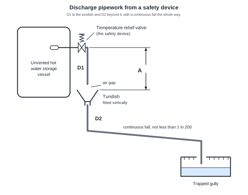
Dimension A is the drop from the temperature relief valve outlet down to the tundish. Approved Document G 3.54 allows no more than 600mm of pipe between the valve outlet and the tundish, so a discharge is seen where you expect it. The other figures belong elsewhere: G 3.56 a. asks for at least 300mm of straight vertical pipe below the tundish, and 150mm, 450mm and 900mm are not Part G dimensions.
D2 is the discharge pipe below the tundish, and it connects directly to the tundish outlet, carrying the discharge on to a safe termination with at least 300 mm of vertical pipe before any bend. D1 is the short metal pipe above the tundish, running down from the relief valve, so it is on the inlet side, not the outlet.
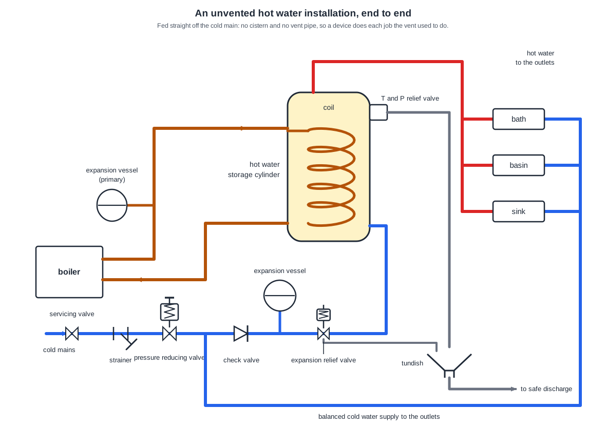
1 is drawn with a spring and adjuster on top of the valve body: a pressure reducing valve, dropping the incoming main to the working pressure the cylinder and its relief valves are rated for. The balanced cold to the outlets tees off downstream of it, which is what makes the supply balanced. The “servicing” valve is the separate one already labelled on the incoming main.
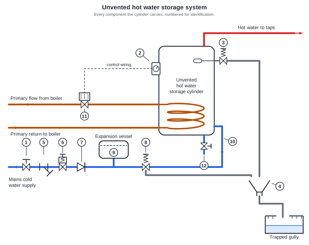
Read the symbols along the cold main: 5 is a strainer, 6 a pressure reducing valve, 7 a single check valve and 8 an expansion relief valve. Those are the four functions a manufacturer builds into one combination valve body. 1 is the stop valve on the incoming service and stays a separate fitting, so “1, 2, 3, 4” cannot be the group.
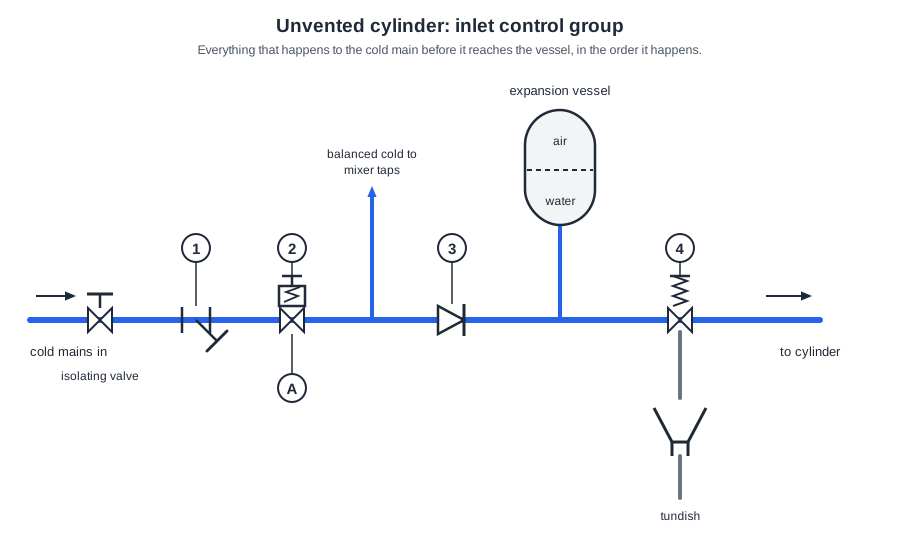
Number 4 is the expansion valve. It opens if the expansion vessel fails and system pressure rises, discharging through the tundish; it is downstream of the check valve so the pressure it relieves is the cylinder side.
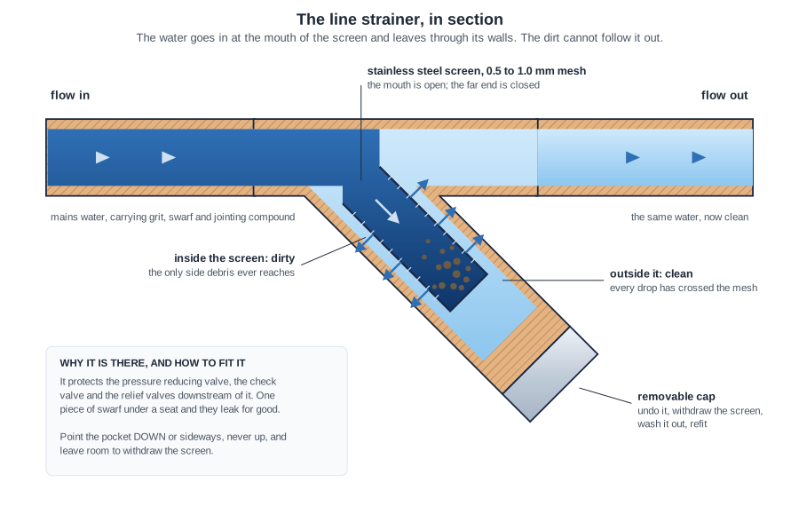
A fine mesh set across the flow with a removable cap below it, so grit and swarf are caught and can be cleaned out at a service instead of travelling on. That protects the valves and controls downstream, which will not seat properly on debris. Reducing “the incoming mains pressure” is the pressure reducing valve’s job; a strainer has no spring and no adjustment.
Approved Document G 3.51 sets D1, the pipe from the safety device down to the tundish, at not less than the nominal outlet size of that device, so a half-inch relief valve outlet gets 15 mm. Going a pipe size larger is the rule for D2 below the tundish, under G 3.58; learners commonly apply it one stage too early.
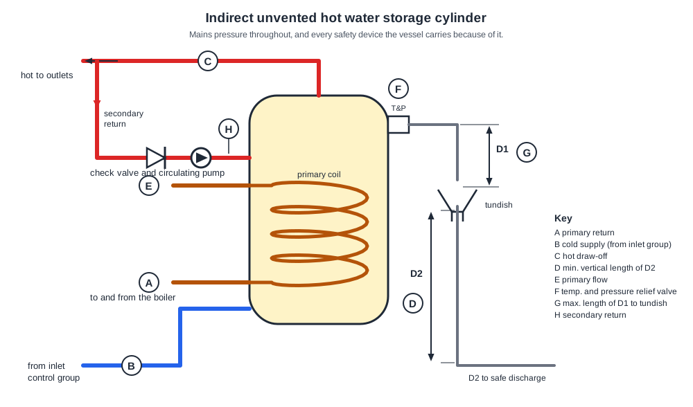
Approved Document G requires the tundish to be within 600 mm of the temperature relief valve, so D1 is at most 600 mm. D marks the other rule: at least 300 mm of vertical D2 pipe below the tundish.
The first metre of every pipe connected to the cylinder is insulated, so heat is not lost out of the store through its connections. The Domestic Building Services Compliance Guide carries the same requirement for Part L.
Number 1, first in the group, is the line strainer: the mesh that keeps grit off the seats of the pressure reducing valve and check valve downstream.
Going further: the lessons behind this article
This article is the public answer. Unit 332 of the Level 3 course takes the same ground to the depth the exam and the synoptic assignment ask for, in 2 lessons:
- Specialist taps and outlet fittings: how they work
- Shower pumps, accumulators and shock arrestors
- Hot water systems: the Unit 332 guide — every article on this unit in one place
- All PlumbMate articles — Level 1, 2 and 3
- The Level 3 course — the whole 8202-35 Diploma