Everything about the hazard came down to one sentence: the danger is heat, not pressure. So the protection is three temperature devices, each set above the one before it, and each doing its work only if the one before has failed.
The short answer
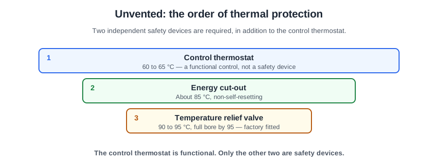
Approved Document G 3.17 requires an unvented hot water storage system to have a minimum of two independent safety devices, in addition to any thermostat provided to control the desired temperature. Add the thermostat back in and you have the three-tier chain taught on site.
| Device | Operates at | What it does |
|---|---|---|
| Control thermostat | 60 to 65 °C | Holds the store at its working temperature |
| Overheat thermostat (energy cut-out) | about 85 °C | Cuts off the heat source and stays off until reset by hand |
| Temperature relief valve | 90 to 95 °C, full bore by 95 | Discharges the hot water to a safe place |
Every setting sits below 100 °C, and that ceiling is the whole point — Schedule 2 paragraph 18 requires the temperature in a secondary hot water system not to exceed it. Paragraph 23 requires a temperature relief valve, or a combined temperature and pressure relief valve, on every unvented vessel with a capacity greater than 15 litres, located directly on the vessel.
How each tier works
The control thermostat is a functional control. On a directly heated vessel it is the immersion heater's user thermostat; on an indirectly heated vessel it is the cylinder thermostat, wired to the heating wiring centre, and the component it switches is the motorised valve on the primary circuit.
The overheat thermostat, or non-self-resetting thermal cut-out, is the second fail-safe. On a direct system it is built into the immersion heater. On an indirect system it is a separate component wired to shut the boiler down or close the motorised valve — a linked arrangement serving both the vessel and the boiler, and the cut-out may be on the boiler itself. If the electrical supply is disconnected, the device must operate to interrupt the heat, and each heat source has its own cut-out.
So on an indirect cylinder whose stored water passes 85 °C, the correct answer is that the high limit thermostat operates the motorised valve to cut off the primary heat supply.
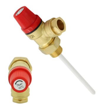
The temperature relief valve is the third fail-safe. It is factory fitted directly on the storage vessel and must not be relocated to any other fitting. It closes automatically after discharging, and it carries a manual test lever so it can be lifted at each service to prove it opens and reseats — the only component in the group with a built-in test device.
Functional or safety? The line examiners test
Functional controls: line strainer, pressure reducing valve, single check valve, expansion vessel or expansion valve, and the control thermostat. They keep the system working day to day and protect the supply. The expansion valve is listed here, although its job is safety: it lets out excess pressure if the vessel or the reducing valve fails.
Safety devices (the two Approved Document G requires): the non-self-resetting thermal cut-out and the temperature relief valve. They protect the user, and act only when the functional controls have already failed.
If you are unsure which a component is, ask what happens without it. If the system works badly, it is functional. If nothing happens until the day it matters, it is a safety device — and safety devices are never optional, never bypassed and never substituted with the wrong part.
One fault follows straight from the sequence. A customer reports the hot taps have gone cold and stayed cold: the control thermostat has failed, letting the store overheat, and the non-self-resetting cut-out has tripped and will stay off until someone resets it by hand.
D1: valve to tundish
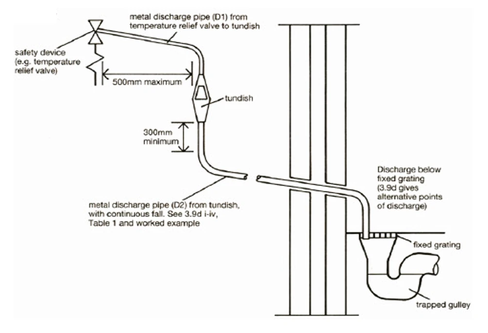
Relief valves do not trickle. They discharge at typically 12 to 20 litres a minute with the water at close to boiling. The discharge pipework has one job: get that water out of the building without hurting anybody, and let somebody see that it happened.
D1 is the short length of metal pipe from the temperature relief valve to the tundish, and it connects straight onto the valve. Its size is not less than the nominal outlet size of the safety device — so a G½ valve gets 15 mm D1.
The tundish
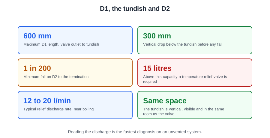
The tundish sits between D1 and D2 and does three things: it gives a visible sign that a relief valve is discharging; it provides the air gap the Water Regulations require between the discharge pipework and the relief valves; and it gives the water somewhere to escape if the pipe below is blocked.
It must be vertical, in the same space as the cylinder, as close as possible to and lower than the safety device, with no more than 600 mm of pipe between the valve outlet and the tundish. That 600 mm is a maximum, and it holds however many valves discharge into the same pipe. Any discharge must be visible at the tundish.
D2: tundish to termination
Below the tundish: at least 300 mm of vertical pipe before any elbow or bend, and then a continuous fall of at least 1 in 200.
The material must be metal, or another material demonstrated to withstand the temperature of the discharge and permanently marked to identify it. That matters because the pipe must support the quick flow of very hot water to a safe termination without deforming or failing.
Size comes from the resistance table: at least one pipe size larger than the nominal outlet of the safety device, unless the total resistance exceeds that of a 9 m straight pipe — then go up a size for each further 9 m band. Bends count.
| Valve outlet | D1 | D2 from tundish | Maximum straight length | Resistance of each elbow |
|---|---|---|---|---|
| G½ | 15 mm | 22 mm | up to 9 m | 0.8 m |
| 28 mm | up to 18 m | 1.0 m | ||
| 35 mm | up to 27 m | 1.4 m | ||
| G¾ | 22 mm | 28 mm | up to 9 m | 1.0 m |
| 35 mm | up to 18 m | 1.4 m | ||
| 42 mm | up to 27 m | 1.7 m |
Worked example. A G½ valve, a 10 m run and five elbows.
Try 22 mm: allowed 9 m, less five elbows at 0.8 m each = 4 m, leaving 5 m. Not enough for 10.
Try 28 mm: allowed 18 m, less five elbows at 1.0 m each = 5 m, leaving 13 m. Ten metres fits, so the answer is 28 mm.
Where one common discharge pipe serves more than one system, it is at least one size larger than the largest individual pipe joining it.
Units, packages and who may fit one
Any unvented system up to 500 litres and less than 45 kW must be a proprietary unit or package satisfying an appropriate standard such as BS EN 12897. Over 500 litres, systems are bespoke and designed to the same safety requirements by an appropriately qualified engineer.
The difference between the two words is examinable. A unit arrives with all the components already factory fitted. A package arrives with the safety devices factory fitted to the vessel and the rest supplied separately as a kit. So on a package the temperature relief valve is always factory fitted — it must be, and must never be relocated — while the expansion valve, strainer, reducing valve and check valve come loose for the installer to fit.
Each unit or package is indelibly marked with the manufacturer's details, the model reference, the rated storage capacity, the operating pressure of the system and of the expansion valve, the operating data for each safety device, and the maximum primary pressure and flow temperature. That plate is where you confirm the pressures for the cylinder in front of you.
Installation is notifiable building work. The building control body must be notified before work commences — unless the installer is registered with a competent person scheme for unvented hot water, in which case they self-certify and give the occupier a certificate of compliance within 30 days, with a copy to the BCB.
Filling, commissioning and the first thing you look at
Commissioning is done to the manufacturer's installation instructions, and the sequence is fixed:
- Visually inspect all connections and pipework before filling.
- Close all drain valves, open the hot taps, then slowly turn on the mains water, so air escapes as the vessel fills. Refilling after maintenance is the same.
- Set and prove the controls, and test the relief valves using the test lever, checking each reseats.
The Benchmark checklist records the safety-critical facts: installer details, that the T&P relief valve is installed and has been tested, and that the discharge pipework has been tested. A satisfied customer, an insurance document or a delivery note is not a commissioning record.
Some rules of order worth memorising: on a reported fault in an occupied property, talk to the end user first. The first activity when maintaining an unvented system is to look for signs of discharge at the tundish. Before any repair, isolate the electrical supply at the local fused spur and prove it dead. To drain the vessel, open a hot tap so air can enter. And never use uncontrolled solid fuel as the heat source for an indirect unvented system — you cannot switch off a fire that is already burning.
Not every complaint is a control fault. A creak from beneath a timber floor whenever hot water is drawn is copper expanding in a joist notch with no allowance made for movement.
🔢 The numbers worth memorising
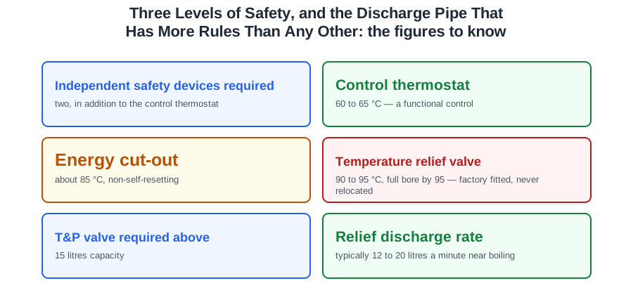
- Independent safety devices required
- two, in addition to the control thermostat
- Control thermostat
- 60 to 65 °C — a functional control
- Energy cut-out
- about 85 °C, non-self-resetting
- Temperature relief valve
- 90 to 95 °C, full bore by 95 — factory fitted, never relocated
- T&P valve required above
- 15 litres capacity
- Relief discharge rate
- typically 12 to 20 litres a minute near boiling
- D1 size
- not less than the nominal outlet of the safety device
- Valve to tundish
- no more than 600 mm
- Below the tundish
- at least 300 mm vertical before any bend, then 1 in 200 fall
- D2 base size
- at least one size larger than the valve outlet
- Competent person certificate
- to the occupier within 30 days
⚠️ Where people go wrong
- Counting the expansion relief valve as one of the two safety devices. It does a safety job against pressure, but it is listed with the functional controls; the two Approved Document G requires are the energy cut-out and the temperature relief valve.
- Relocating a temperature relief valve to a nearby fitting. It is factory fitted directly on the vessel.
- Measuring D2 in straight metres and ignoring the bends. Each elbow eats 0.8 to 1.7 m of the allowance.
- Fitting more than 600 mm of pipe between the valve and the tundish.
- Running D2 uphill over an obstruction. It falls continuously at 1 in 200 all the way out.
- Expecting the expansion valve to be factory fitted on a package. Only the safety devices are — the rest comes loose.
- Heating an unvented cylinder with an uncontrolled solid fuel appliance. The cut-out cannot switch off a fire.
- Draining an unvented vessel without opening a hot tap. It will not drain against a vacuum.
📝 10-Question Self-Test
Straight from the Level 3 course question bank. Click an option to see whether you got it right — the explanation appears instantly, and there is nothing to submit.
A kitchen sink is not one of the outlets that must have a thermostatic mixing valve, so the first step is the control thermostat. Bear in mind the store still has to be held at 60 degrees C or above for Legionella control, so if the tap is genuinely too hot at that setting the answer becomes a mixing valve at the outlet.
With the thermostat and its energy cut-out both gone, the immersion heater keeps heating and the water in the cylinder is driven past 100 °C. The open vent is the route of least resistance, so very hot water and steam are pushed up it and discharge into the cold water storage cistern. Nothing switches itself off at 100 °C; that was the failed cut-out job.
A single-point heater sits at the outlet it serves and heats that outlet only, which is the definition of a localised, or point of use, system. Centralised is the tempting pick, but that describes one store piped to every tap in the dwelling. “Indirect” and “sealed primary” describe how a vessel is heated, not the area it serves.
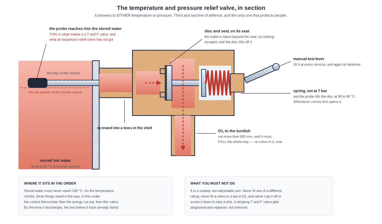
The probe reaches through the shell into the stored hot water, so when that water gets too hot the valve opens and discharges to the tundish while cold feeds in behind it. Schedule 2 paragraph 23 requires one directly on every unvented storage vessel over 15 litres, with enough capacity that the stored water cannot exceed 100°C. Cutting “the electrical supply to the immersion heater” is the thermal cut-out’s job.
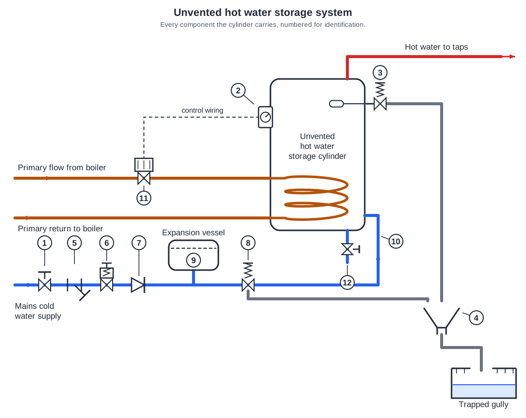
Those four are the inlet control group: strainer at 5, pressure reducing valve at 6, single check valve at 7 and expansion relief valve at 8, cast into one body on a modern kit. “3, 4, 5 and 6” drags in the temperature relief valve and the tundish, which are cylinder safety devices and stay separate from the inlet group.
The three tiers are the control thermostat at 60 to 65 °C, the non-self-resetting energy cut-out at about 85 °C, and the temperature relief valve at 90 to 95 °C, each set above the last and acting only when the one before it has failed. Approved Document G 3.18 names the second and third. An expansion vessel is a functional control; it protects the system, not the person.
On a directly heated cylinder the immersion heater is the only heat source, so both its thermostat and its energy cut-out have to have failed before the water can be driven past 100 °C and up the vent into the cistern. An undersized vent pipe or a part-closed gate valve on the cold feed would slow the system or make it noisy; neither of them adds heat.
Schedule 2 paragraph 18 of the Water Regulations requires the temperature of the water in a secondary hot water system never to exceed 100 °C, and every control on an unvented cylinder is set below that ceiling. 95 °C tempts because it is the point at which the relief valve is discharging at full bore, but that is how the limit is kept, not the limit itself.
Localised means a heater fitted at the outlet it serves, and a point of use heater does exactly that whether it is vented or unvented. The combination boiler is the tempting pick because it heats instantaneously with no store, but it feeds the whole dwelling through distribution pipework, which makes it centralised.
The pipe has to carry water at about 95 C, the top of the range at which the temperature and pressure relief valve lifts, so Approved Document G 3.57 requires D2 to be metal or a material proved to withstand it. Table 1 then sizes the pipe on resistance rather than temperature: with a 15 mm minimum D1, 9 m in 22 mm, 18 m in 28 mm and 27 m in 35 mm, less 0.8 m for each 22 mm elbow, 1.0 m for each 28 mm and 1.4 m for each 35 mm.
Going further: the lessons behind this article
This article is the public answer. Unit 332 of the Level 3 course takes the same ground to the depth the exam and the synoptic assignment ask for, in 3 lessons:
- Three levels of safety on an unvented cylinder
- Discharge pipework: the tundish, D1 and D2
- Units, packages, approval and commissioning records
- Hot water systems: the Unit 332 guide — every article on this unit in one place
- All PlumbMate articles — Level 1, 2 and 3
- The Level 3 course — the whole 8202-35 Diploma