A caretaker reports that the basement booster set runs for a moment, stops, and starts again a few seconds later, all day long. The pumps are fine. The fault is in the vessel beside them.
The short answer
Booster pumps are centrifugal — horizontal single-stage, or on a booster set usually vertical multi-stage, where several impellers in a column each add pressure to the last (BS 8558 Annex A.6). They are installed as duplicate pumps, two or more in parallel, sized so that peak demand is still met if one pump fails.
There is no dedicated standby. The controls rotate the starting sequence so every pump takes its turn as lead, because a pump that never runs holds stagnant water and can seize. That is the answer to the site foreman's question about keeping the second one as a spare.
What sets the pump duty
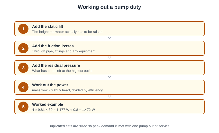
Three things (BS 8558 A.6):
- the static lift — the height of the building the water has to climb;
- the friction losses in the pipework and valves on the way up;
- the residual pressure the outlets need when the water arrives.
Pumps and pipes are also sized to limit water hammer from surge when the set starts and stops.
The worked example the exam uses
Water is pumped to a storage cistern at 4 kg/s through a total pipe length, fittings included, of 30 m. The pump is 80 per cent efficient.
Hydraulic power = mass flow × g × head = 4 × 9.81 × 30 = 1,177 W.
The pump turns only 80 per cent of the power it takes into water power, so divide by the efficiency: 1,177 ÷ 0.8 = 1,472 W. Specify at least a 1.5 kW pump.
The step people drop is the second one. Dividing by efficiency makes the answer bigger, not smaller — a pump has to take in more than it delivers.
Packaged or self-assembled
A booster set is normally a factory-assembled package: pumps, manifolds, a control panel that starts and stops them in sequence, and a pressure accumulator, all on one skid and pre-wired, leaving only the final plumbing and electrical connections.
On a diagram of an integrally controlled booster pump, the small sensor on the discharge is the transducer and the vessel beside the pump is the accumulator.
A self-assembled set builds the same thing from separate parts — pumps, non-return valves, isolating valves, gauges, pressure switches, a pressure vessel and, with a pneumatic vessel, an air compressor. The installer then carries the responsibility for matching the vessel to the pumps and setting the switch pressures.
Either way, a Bourdon pressure gauge on the inlet and on the outlet of the pumps shows whether a pump is performing. If the outlet does not show the expected rise while the pump is called, it is not delivering.
Why the vessel exists, and the caretaker's fault
Where a boosted supply serves outlets on several floors, level switches are impractical, so the pumps are controlled by pressure — and a vessel stops them cycling.
A pneumatic pressure vessel holds a small reservoir of water under a cushion of compressed air. The pumps top up the water; the air holds the system at its design pressure while the pumps are idle. Its principal purpose is to stop the pump set cycling on and off for short periods.
It is sized on the pump flow rate, the cut-in and cut-out pressures, and the permitted number of pump starts per hour. The usable volume between the two pressures follows Boyle's law. Exam questions often shorten this to "system volume and operating pressure".
Do not confuse it with the expansion vessel on an unvented hot water system, which is sized on the volume of water heated and holds at least 4 per cent of it (BS EN 806-2 clause 10.4). Different job, different calculation.
The pre-charge is the air pressure in the empty vessel, set to 90 per cent of the pump cut-in pressure (80 to 90 per cent is the working range) so a little water always remains and the bladder never collapses. Set it wrong and the vessel holds almost no usable water between cut-out and cut-in, so every draw-off empties it at once.
That is the caretaker's set. A pump that cuts out and restarts a few seconds later has an incorrect pre-charge. Its cousin, a set that simply keeps switching on and off, has an accumulator that has lost its pressure altogether. Both are cured at the air valve, not at the pump.
Which switch does what — and which one failed
Every switch on the set either starts the pumps or stops them.
A pressure switch is a diaphragm working contacts at a set pressure. The low pressure switch gives the cut-in: as water is drawn and pressure falls to its setting, it starts the pumps. The high pressure switch gives the cut-out: once the system pressure is reached, it switches them off.
So a pump that has been running normally but no longer starts when water is drawn has probably lost its low pressure switch. A pump that will not stop points at the high one.
A transducer senses the same thing electronically, converting pressure into a voltage the panel reads. With a continuous signal the panel can vary pump speed to hold the pressure steady, run the compressor, or trip on over-pressure. On a mains-boosting set with no cistern, the transducer is the only thing that can call the pumps.
A float switch makes or breaks a circuit to remote equipment, and on a booster system it does two different jobs in two places:
- In the high-level storage cistern, it starts the pumps as the level drops (about half full) and stops them about 50 mm below float valve shut-off.
- In the break cistern, a low-level switch stops the pumps when the water is low so they cannot run dry — BS 8558 A.2 calls this the dry-run protection level switch. If it fails, the pumps run dry, overheat and seize.
On a silent set: a half-empty high-level cistern with the pumps not called points to its float switch or circuit. A nearly empty break cistern means the dry-run switch has done its job, and the fault is upstream in the cistern feed.
Working on the set safely
Isolate the electrical supply, prove dead and lock off. Before removing a gauge, confirm the section of pipe is fully drained.
BS EN 806-5 Annex A lists a pressure booster pump for attention once a year, serviced to the manufacturer's instructions. The annual service checks the vessel pre-charge and cleans the filters, and a visual inspection confirms the cistern water level is correct. After planned maintenance the whole installation — pumps, pipework and vessels — is flushed with clean water introduced at the break cistern before it returns to service (BS 8558 clause 5.2.3.1).
🔢 The numbers worth memorising
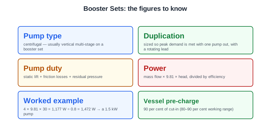
- Pump type
- centrifugal — usually vertical multi-stage on a booster set
- Duplication
- sized so peak demand is met with one pump out, with a rotating lead
- Pump duty
- static lift + friction losses + residual pressure
- Power
- mass flow × 9.81 × head, divided by efficiency
- Worked example
- 4 × 9.81 × 30 = 1,177 W ÷ 0.8 = 1,472 W → a 1.5 kW pump
- Vessel pre-charge
- 90 per cent of cut-in (80–90 per cent working range)
- Vessel sizing
- pump flow rate, cut-in and cut-out pressures, permitted starts per hour
- Service interval
- once a year (BS EN 806-5 Annex A)
⚠️ Where people go wrong
- Multiplying by the efficiency instead of dividing. A pump takes in more than it delivers, so the figure goes up.
- Keeping one pump as an untouched standby. A pump that never runs holds stagnant water and seizes — the sequence rotates for a reason.
- Blaming the pumps for short-cycling. A restart within seconds is an incorrect pre-charge, cured at the air valve.
- Confusing the booster vessel with an unvented expansion vessel. Different sizing basis entirely.
- Diagnosing “no water at the top” without asking which cistern is empty. A low break cistern means the dry-run switch worked and the fault is upstream.
- Flushing after maintenance from anywhere but the break cistern.
📝 10-Question Self-Test
Straight from the Level 3 course question bank. Click an option to see whether you got it right — the explanation appears instantly, and there is nothing to submit.
A pressure switch either side of a pump reads the pressure rise across it. If the downstream switch does not see the expected rise while the pump is called, the pump is not performing.
With no cistern there is no float or level switch to call the pumps. A pressure transducer (or pressure switch) on the pump discharge senses the fall in pressure when outlets open and starts the pumps.
No standard fixes a pre-charge percentage: BS 8558 says only that the accumulator is pre-charged with air to suit the system pressure. The manufacturers' convention, and the figure to use, is about 90 per cent of the pump cut-in pressure (working range 80 to 90 per cent), so a little water always stays in the vessel and the bladder never collapses against the shell. At 110 per cent the pre-charge is above cut-in, the vessel holds no water at all, and the pump cycles on every draw-off.
The break cistern feeds the pump. A low-level switch there is what stops the pump when the break cistern empties; if it fails the pump keeps running against no water, overheats and seizes. Switches in the high-level cistern control pump start and stop on demand, not dry running.
A float switch rises and falls with the water and makes or breaks a circuit, so it is the only item here that can switch anything: in a high level cistern it starts the pumps as the level drops, and in a break cistern it stops them before they run dry. A pressure gauge and a sight glass only display; a non-return valve just blocks reverse flow.
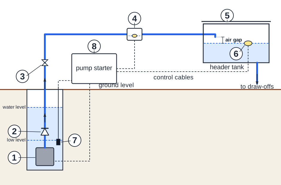
6 is the float switch in the header tank. As stored water is drawn off the float falls and its switch signals the pump starter to run the well pump; when the tank fills the float rises and stops it again. The valves drawn are both on the rising main: the non-return valve (2) in the well, which stops the delivery pipe emptying back down, and the isolating valve (3) at the wellhead. No pressure gauge or drain valve is shown.
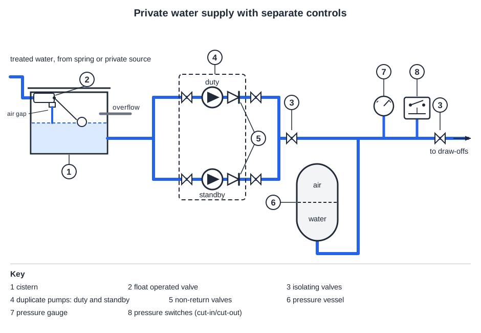
6 is the accumulator, a sealed vessel with air trapped above a diaphragm. The pumps compress that air as they charge the system, and when a tap opens the air pushes the stored water back out, holding the pressure up and covering small draw-offs without the pumps starting. The pressure switch alongside the gauge only senses pressure and tells the pumps when to run; it stores nothing.
The pressure vessel is the component that works on air: compressed air above the stored water pushes it back into the system while the pumps are idle, so small draw-offs do not start a pump and the number of cycles falls. A non-return valve and a float switch contain no air, and a pressure reducing valve only holds down the downstream pressure.
The high pressure switch gives the cut-out: its diaphragm works the contacts once the system reaches the set pressure and the pumps stop. The low pressure switch does the opposite job and starts them. A pressure gauge shows the pressure but switches nothing, and the float switch in the break cistern only stops the pumps running dry.
Fit a gauge on the pump inlet and another on the outlet: the difference between the two readings is the pressure the pump is actually generating. If the outlet does not rise as expected while the pump is called, it is not delivering. A running-hours counter tells you only that it ran, not how well, and cistern contents say nothing about the pump.
Going further: the lessons behind this article
This article is the public answer. Unit 331 of the Level 3 course takes the same ground to the depth the exam and the synoptic assignment ask for, in 2 lessons:
- Booster sets: duplicate pumps, packaged units and annual servicing
- Booster sets: the pressure vessel and the control switches
- Cold water systems: the Unit 331 guide — every article on this unit in one place
- All PlumbMate articles — Level 1, 2 and 3
- The Level 3 course — the whole 8202-35 Diploma