A joint you find on a walk-round costs a minute. The same joint found under test pressure, with the ceiling closed and the decorators in, costs a day.
The short answer
The sequence is fixed and the order carries the marks: inspect dry, then fill, then test. Water hides faults as much as it reveals them — once the system is full, every change means a drain-down, and a fault under pressure can damage finishes.
What the dry inspection is measured against
An inspection is only as good as the paperwork it is checked against. Before you start, have to hand:
- The specification — pipe sizes, materials, storage volumes, pump duties, design pressures. A fitted component that does not match it is reported to your manager. It is not quietly accepted: a substitution is not your decision.
- The drawings, including as-fitted or schematic diagrams in an existing building, so only the intended parts of a system are worked on.
- The manufacturers' instructions for every component. Only the manufacturer knows the correct set-up sequence, and ignoring it can void the warranty.
- The Water Regulations, BS EN 806-4 and BS 8558, and the workmanship checks in BS 8000-15.
- The undertaker's consent and any conditions, the risk assessment and method statement, and any permit to work.
The walk-round
The apprentice has finished the pipework and says it is ready to fill. You take the drawing and walk it, and within ten minutes you have found an open end behind the bath panel, a compression joint with no olive, and a cistern sitting on two loose boards. None of them would have survived the fill.
- All open ends capped and every valve at the limit of the section closed.
- Every capillary joint soldered and every compression joint tightened — look for dry joints and missing olives.
- Enough clips, brackets and supports; the pipework secure. Loose pipework becomes noisy pipework at high pressure.
- Cisterns on a proper base, clean, free of debris, with correctly fitting covers before testing.
- Float-operated valves provisionally set to the right water level.
- Appliance isolation valves and taps off, ready to be opened one at a time.
- The correct backflow devices in the right places, and valves carrying their identification labels.
- Underground pipework at the correct depth and not backfilled before it was inspected.
And the inspector you have to invite: the water undertaker must be given the opportunity to inspect, with prior notice before any statutory inspection or test (BS 8000-15 clause 4.1.1). Do it before the system is filled, so anything they want changed can be put right without a drain-down.
The trench is the one item that cannot wait. Once a service pipe is buried, the depth and the joints are invisible — so the underground run is inspected in the open trench and tested before backfilling as well. A groundworker who backfills to tidy the site has removed the evidence.
Extra checks by system type
| System | Extra visual checks |
|---|---|
| Direct | Stop valve and drain-off at entry; servicing valves to each appliance; any PRV fitted the right way round; backflow protection at hose taps, WCs, bidets and appliance connections |
| Indirect | Cistern base and support; screened warning pipe and overflow; insect-proof but not airtight cover; float valve and servicing valve on the inlet; gate valves on the distributing pipes; insulation on the cistern and roof-space pipes |
| Boosted | Break cistern and its float valve; duplicate pumps with isolating valves each side; low-level float switch for dry running; pressure switch or transducer; accumulator with its single connection, pre-charge and a check valve on its supply side; pressure gauges; electrical supply isolated until the system is full |
The accumulator usually has one pipework connection: water enters and leaves through it, and the air side has only the pre-charge valve. The check valve on its supply side stops stored water flowing back into the supply pipe when the mains pressure drops.
What water goes in
A site agent offers the water bowser because the temporary mains connection is not in yet. The answer is no.
The system is filled with fluid category 1 water taken directly from the undertaker's main. Softened water, rainwater or bowser water would contaminate a system that is about to carry drinking water. BS EN 806-4 clause 6.1.1 adds that it should be drinking water free of particles of 150 µm or larger, which on large jobs means filling through a mechanical filter.
And one practical rule that catches people: do not fill a system until the drainage is connected, because you will not be able to flush it afterwards.
The initial fill is made at the system's normal operating pressure — the mains for a direct system, the head of the cistern for a distributing system, the pump set's working pressure for a boosted one. It is not the test pressure. The fill finds weeping joints at low pressure, where a joint can be remade after a local drain-down. The test comes later, from a test pump, once the system is full and settled.
Filling without air locks
The top-floor bathroom splutters, the loft cistern will not fill, and every joint is tight. Nothing is leaking. The distributing pipe has an air lock, and it got there during the fill.
Fill slowly, with the highest draw-off point open so air is expelled as the water rises. Every high point needs an air vent or an open tap, closed again once water shows.
On cistern-fed pipework there is a subtlety that explains the spluttering. Let the cistern fill to its working level first and let the float valve shut, then open the gate valves on the distributing pipes so the full head is available and the pipe fills at full bore. A trickle fill through a half-open valve is the classic way to trap air: the water creeps along the bottom of the pipe and leaves a pocket at every high point.
Water goes to the bottom; air goes to the top; the top has to be open. On a rising main the top is the cistern or the highest tap; on a distributing pipe it is the highest outlet on that pipe, which may not be the highest outlet in the building.
Large and multi-storey systems are filled section by section: leaks are found in a small area, air locks are less likely, and if something goes wrong only one section has to be drained. Station an operative at the main isolation valve so it can be shut the moment a leak is called.
The test pressure
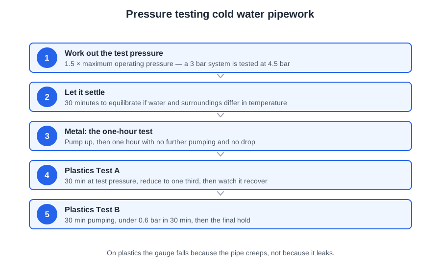
Schedule 2 paragraph 12(1) requires the system to withstand an internal pressure of not less than 1.5 times the maximum pressure to which the installation is designed to be subjected in operation.
An installation designed for 3 bar is tested at 3 × 1.5 = 4.5 bar. A system on a 2 bar supply is tested at 3 bar. The maximum working pressure is normally the incoming mains pressure measured after any pressure reducing valve. The test covers the whole installation, not only the new section, and vulnerable components that cannot take the test pressure are removed and replaced with temporary pipe.
Metal: the one-hour test
Copper, stainless steel and low carbon steel are rigid. They do not stretch appreciably, so if the gauge falls the water has gone somewhere.
Schedule 2 paragraph 12(2)(a): pump the whole system to the test pressure; the test then continues for one hour without further pumping; the pressure is maintained; and there is no visible leakage throughout.
Where the water and the surroundings differ in temperature by more than 10 K, allow 30 minutes at test pressure for temperature equilibrium before the hour starts. Water expands as it warms, so a cold fill in a warm building would show a rise, and a warm fill in a cold roof space a fall, with nothing wrong anywhere.
Plastics: why the gauge falls when nothing leaks
A polybutylene system pumped to 4.5 bar and left for an hour reads 4.1 bar at the end, and the plumber spends the afternoon hunting a leak that does not exist. The pipe was stretching.
Plastics pipe expands under pressure: the pipe swells, the same water fills a larger volume, and the gauge falls. The expansion is largest at first and tails off as the material creeps into its new shape. Both plastics tests share one idea — let the expansion happen first, then judge what the pressure does afterwards.
| Stage | Test A | Test B |
|---|---|---|
| Pumping | Whole system pumped to the test pressure for 30 minutes | Whole system pumped to the test pressure for 30 minutes; pressure noted |
| After pumping stops | Pressure reduced to one third of the test pressure | Test continues 150 minutes without further pumping |
| Pass criterion | Pressure does not drop below one third over the following 90 minutes | Drop less than 0.6 bar after the next 30 minutes and less than 0.8 bar after 150 minutes |
Dropping to one third in Test A lets the plastics relax and grip the water, so any further fall is a leak. Test B works by staged limits, and the 0.8 bar figure is 0.6 + 0.2, not an allowance of its own.
Worked example. A system under Test B drops 0.8 bar in the first 30 minutes and then holds perfectly for 120 minutes. Total drop 0.8 bar — but the first stage allowed only 0.6, so it is a fail. Each stage has to be met on its own.
Which standard, and how to test it
BS 6700 was withdrawn on 1 August 2012; the procedure is now in BS EN 806-4 with BS 8558 alongside. BS EN 806-4 sets its own procedures A, B and C at a test pressure of 1.1 times the maximum design pressure — but when a question is about the Water Regulations, or simply asks for the test pressure and hold time, give the Regulations' figures: 1.5 times, one hour for metal, Test A or B for plastics.
Use a hydraulic test pump with a calibrated gauge accurate to 0.2 bar, range 0 to 16 bar, fitted at the lowest point of the system. Testing with compressed air or gas is possible but not recommended because of the risk of explosion: water is nearly incompressible, so a burst under hydraulic test releases little energy, and a gas-filled system stores a great deal.
If the pressure falls, first check that no isolating valve is passing — a valve letting by into an unfilled section drops the gauge just as a leak does. If there is a genuine drop, locate and repair the leak, then repeat the test. Have the passed test witnessed and signed, and record the pressure, duration and result.
The three shortcuts that turn a test into a lie
Twenty minutes into the hour the gauge has dropped a quarter of a bar, nobody is watching, and a quick stroke of the pump would put the needle back.
- Never top up the pressure and record the original figure. The test is one hour without further pumping; a topped-up test has proved nothing.
- Never lower the test pressure until it holds. A system that holds 3 bar has not been tested at 4.5.
- Never record the drop and hand over. A recorded fall is a recorded failure, and the leak is still there behind the plasterboard.
And test as the work proceeds: interim tests on each section, especially work that will be concealed, are not the same as the final test on completion. Passing an interim test does not count as the final one.
🔢 The numbers worth memorising
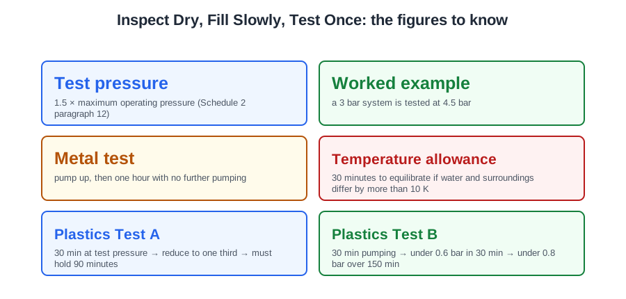
- Test pressure
- 1.5 × maximum operating pressure (Schedule 2 paragraph 12)
- Worked example
- a 3 bar system is tested at 4.5 bar
- Metal test
- pump up, then one hour with no further pumping
- Temperature allowance
- 30 minutes to equilibrate if water and surroundings differ by more than 10 K
- Plastics Test A
- 30 min at test pressure → reduce to one third → must hold 90 minutes
- Plastics Test B
- 30 min pumping → under 0.6 bar in 30 min → under 0.8 bar over 150 min
- Gauge accuracy
- 0.2 bar, range 0–16 bar, fitted at the lowest point
- Fill water
- fluid category 1, direct from the main, free of particles 150 µm or larger
- BS EN 806-4 procedures
- 1.1 × maximum design pressure — not the Regulations’ figure
⚠️ Where people go wrong
- Filling before the drainage is connected. You will not be able to flush it.
- Giving a plastics system the metal test. It expands under pressure, and the falling gauge is the material, not a leak.
- Reading Test B’s 0.8 bar as the whole allowance. It is 0.6 + 0.2, and each stage has to pass on its own.
- Trickle-filling a distributing pipe through a half-open gate valve. Let the cistern fill and the float valve shut first, then open it fully.
- Hunting a leak before checking whether an isolating valve is passing into an unfilled section.
- Topping up during the hour, lowering the pressure until it holds, or recording the drop and handing over. All three are the same lie.
- Backfilling a trench before the underground run is inspected and tested.
📝 10-Question Self-Test
Straight from the Level 3 course question bank. Click an option to see whether you got it right — the explanation appears instantly, and there is nothing to submit.
The people whose water will be shut off and whose outlets will be tested are the occupants; they are told first.
Commissioning follows the manufacturers' instructions for each component (pumps, valves, cisterns), alongside the Water Regulations and the specification. None of the other documents bears on commissioning.
Air trapped at a high point blocks the bore and starves the outlets below it, so the system is filled slowly with the top tap or air vent open and closed again once water shows. On cistern-fed pipe let the cistern reach working level first, then open the gate valves fully, because a trickle fill traps air. Excessive pressure is not a filling risk: the fill is made at normal operating pressure.
Schedule 2 paragraph 12(1) of the Water Supply (Water Fittings) Regulations requires the water system to withstand an internal pressure of not less than one and a half times the maximum pressure it is designed to be subjected to in operation, which the Regulations call the test pressure; that is 50 per cent above the maximum operating pressure, and BS 8000-15 (clause 4.5 commentary) asks for at least 1.5 times as well. BS EN 806-4 6.1.2 on its own tests steel, stainless steel and copper pipes at 1.1 times the maximum design pressure, 10 per cent above it, but it allows the test pressure to be increased to comply with regulations, and in the United Kingdom the Regulations require 1.5 times. The withdrawn BS 6700 gave the same 1.5 times.
BS EN 806-4 orders the first three steps: filling and hydrostatic pressure testing (clause 6.1), then flushing as soon as possible after the pressure test and immediately before commissioning (6.2), then disinfection where it is specified (6.3). The flow check at every draw-off tap, shower fitting and float-operated valve and the performance tests on specialist items come from BS 8000-15 section 4, and handover follows once every test is satisfactory. The pressure test is first in every ordering.
Commissioning starts with a visual inspection: every joint, support, valve and cistern is checked against the specification before any water is admitted. Labelling, adjustment and handover come at the end.
The test water is fluid category 1, wholesome water supplied by the water undertaker, because whatever is left in the pipe when the job is handed over will be drunk; BS EN 806-4 (6.1.1) says the installation is filled only with drinking water. Category 2 is the tempting choice, but that is water whose appearance, taste or temperature has changed, and the guidance lists a domestic softener regenerated with common salt as a category 2 example, so softened water would leave the new system holding water that is no longer category 1.
BS EN 806-4 clause 6.1.2 allows 30 minutes for temperature equilibrium where ambient and water temperature differ by more than 10 K, after the test pressure has been applied. Water expands as it warms, so a gauge read too early shows a rise that flatters a leaking system or a fall that condemns a sound one. Only then is the pressure held, for at least 10 minutes.
Schedule 2 paragraph 12 requires the system to withstand an internal pressure of not less than one and a half times the maximum pressure it is designed to be subjected to in operation, and that figure is the test pressure. There is no fixed bar figure: a flat 10 bar would be far above one and a half times working pressure on most jobs and could damage fittings.
A metallic system is pumped up to the test pressure of one and a half times the maximum operating pressure and then held for one hour with no further pumping, no pressure loss and no visible leakage, which is what Schedule 2 paragraph 12(2)(a) requires. Fifteen minutes appears as a stage inside one of the older plastics procedures; on its own it is nowhere near long enough to expose a slow weep.
Going further: the lessons behind this article
This article is the public answer. Unit 331 of the Level 3 course takes the same ground to the depth the exam and the synoptic assignment ask for, in 5 lessons:
- Visual inspection: the documents and the dry checklist
- Direct, indirect and boosted systems: extra checks and first fill
- Filling: avoiding air locks, stabilising and inspecting for leaks
- Soundness testing: test pressures for metal and plastics pipework
- Soundness testing: current standards, equipment and procedure
- Cold water systems: the Unit 331 guide — every article on this unit in one place
- All PlumbMate articles — Level 1, 2 and 3
- The Level 3 course — the whole 8202-35 Diploma