A householder rings. There is a loud bang from somewhere in the pipework, it does not happen all the time, and she wants it fixed. The cheapest instrument you own is a conversation, so the job starts there.
The short answer
Fault finding on a cold water system draws on four sources of information: the end user, the manufacturer's information, fault diagnosis flow charts, and the system history.
Then it becomes measurement. The fault is located by the difference between what the commissioning record says the system did, and what it does now.
What the end user can tell you — and what they cannot
The person who uses the system every day is the first source, and the right way to get it is a verbal discussion. They cannot give you pipe sizes, pressure readings or valve settings. What they are uniquely placed to give is the immediate history:
- When the fault first occurred and how they noticed it.
- What characteristics it shows — constant or intermittent, worse at certain times of day.
- Whether there were any unusual noises, which often point straight at the type of component that failed.
- Whether they have attempted a repair themselves — because that work may have to be undone before the real fault can be found.
An intermittent noise is the case for talking first, because it may not happen while you are standing there. Suppose she says it only happens after the WC has been flushed. That one detail points at the cistern refilling, and three causes present themselves: pipework insufficiently clipped, so it moves as the flow starts and stops; pipework under the floor not lagged, so it vibrates against the structure; or a defective float valve washer, letting vibration pass through the diaphragm as the cistern refills.
The same habit works on smaller complaints. A tap that vibrates and gives a poor flow usually has a loose jumper plate — the disc carrying the washer chattering in the flow.
The manufacturer's literature comes before your hunch
A booster set keeps tripping. One engineer resets the panel, another swaps a pressure switch on a hunch, and neither opens the folder on the wall beside the set.
Of all the documents, the manufacturer's instructions are the first to consult when diagnosing a fault on a component. BS EN 806-5 clause 5 requires them to be available, retained and followed, and clause 12 says routine maintenance shall be in accordance with them.
Fault finding in that literature takes three forms: a list of known problems and symptoms; a diagnostics flow diagram; and the technique for replacing the faulty part with a parts list. The flow chart lives in the operation and maintenance instructions — not the sales brochure and not the warranty card. When ordering, quote the equipment model number and the part number.
How a flow chart thinks
A flow chart turns fault finding into a logical sequence, and it always starts with the cheapest and most likely cause. If a pump motor will not run at all, the first check is the electrical supply — fuse, isolator, breaker, connections — because a scaled impeller, a blocked strainer or an air lock changes how the pump performs, not whether the motor turns.
| Symptom | First check | Then check | Likely fault |
|---|---|---|---|
| Motor does not run | Electrical supply, breakers, connections | Capacitor (single phase), windings | Loss of supply, failed capacitor, open winding |
| Motor runs, outlets dry | Is the shaft turning the impeller? | Rotation direction, priming, suction valves | Broken impeller shaft, air lock |
| Pump runs but flow is low | Strainers and check valves | Rotation, air in pump | Clogged strainer, wrong rotation |
| Water through the standby pump | Non-return valve on the standby discharge | — | Failed check valve |
The system history: the folder and the logbook
The fourth source is the record of what the system did when it was new and what has happened since.
The commissioning record holds the technical results: the type of pressure test and how long the test pressure was held, the disinfectant concentrations and contact time, the flow rates and pressures at the outlets, the suction and discharge pressures of any pumps, and the accumulator pre-charge. Commercial documents — prices, invoices, maintenance contracts — do not belong on it.
The logbook of all work and inspections lives in the plant room (BS 8558 Annex A.7). Previous call-outs, parts replaced, alterations. A discharge pressure that has fallen since the commissioning sheet was written is a fault located by subtraction.
And the logbook tells you whether the checks that should have happened did. BS EN 806-5 Annex A gives the intervals a diagnostic visit is measured against:
| Component | Inspection | Routine maintenance |
|---|---|---|
| RPZ valve, type BA | Every 6 months | Once a year |
| Verifiable check valves, EA and EC | Once a year | Once a year |
| Non-verifiable check valves, EB and ED | Once a year | Replace every 10 years |
| Pressure booster pump | Once a year | To the manufacturer's instructions |
| Water softener | Every 2 months | Every 6 months |
A logbook with no softener entry for a year, when the standard wants it inspected every two months, is itself a finding worth writing down.
Isolation: the valves the Regulations require
The float valve on a storage cistern is passing and has to come out. There is no servicing valve on the inlet, and the stopvalve at the point of entry turns and turns and shuts off nothing. Before you can fix the fault you have to isolate a system built without the means.
The Regulations make sure the means exist. Schedule 2 paragraph 10 requires every supply or distributing pipe to separate premises to have a stopvalve that shuts off that supply without shutting off any other premises. Paragraph 11 requires systems to be capable of being drained down, with enough servicing valves and drain taps to minimise the water discharged, and enough stopvalves for isolating parts of the pipework. Paragraph 16 puts a servicing valve on the inlet of every storage or flushing cistern and the outlet of every storage cistern — the valve our cistern was missing.
Shut off the smallest section possible. Where no local valve exists, a pipe-freezing kit may avoid turning off the whole building.
Draining down, and the water that stands still
Drain from the drain taps at the low points. BS 8558 clause 4.3.16 asks for pipework downstream of every stopvalve to fall continuously towards draining or draw-off taps.
Draining only works if air can enter: open the draw-off taps and float valves above the section, or an air inlet valve where fitted, because check valves at outlets can hold a vacuum and a cylinder can collapse. A hose on a drain tap must discharge freely into the air and never be submerged. On a pressure vessel, confirm the gauge reads zero before breaking any joint.
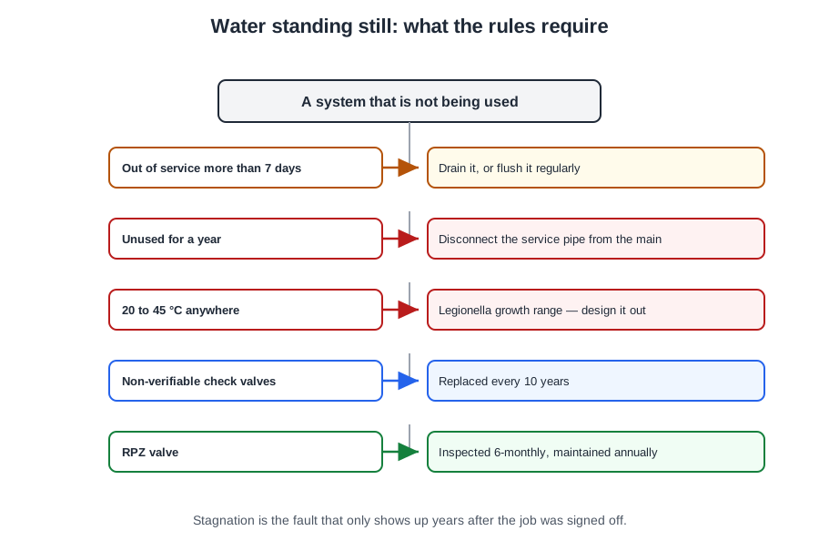
Then the standing-water rules. BS EN 806-5 clause 7: an installation not going to be operated within 7 days of completion, or out of service for more than 7 days, shall either be shut off at the supply stop valve and drained, or be flushed regularly. A service pipe not used for a year or more should be disconnected from the main.
The reason is stagnation. Standing water between 20 °C and 45 °C is the condition HSE ACOP L8 identifies for Legionella growth, and BS 8558 clause 6.2.4 says pipework to a disconnected appliance must be disconnected at its source rather than left as a dead leg.
Related, and often confused with it: blue water is a copper problem, not a dissimilar-metal one. Very fine copper corrosion products turn the first draw blue-green and stain sanitaryware, and the main cause is infrequent use — water standing in new copper that has not yet formed its protective film, or pipe left with flux residue. It is cleared by thorough flushing.
Measuring what the system does now
Diagnostic checks are measurements, not opinions.
- A weir gauge under an outlet gives the flow rate from the height the water reaches in its slot. It over-fills at high flows and reads false.
- A Bourdon pressure gauge screwed to an outlet gives static pressure; fitted permanently either side of a booster set, a pair of them show inlet and outlet pressure.
- A combined pressure and flow meter gives static, running and flow readings together.
Readings are compared with the design specification, the manufacturer's instructions and the draw-off flow rates in BS EN 806-3. Pipe length, bore roughness and the number of tees and elbows all cost pressure; the pH of the water has no effect on flow, and it sits in exam answer lists to catch people.
Where the supply is insufficient, work the BS EN 806-5 clause 9.2 list: part-closed stop valves, blocked filters and spray outlets, a defective PRV, too many outlets open at once, scale, a change in supply pressure, burst or frozen pipes. On a private supply, flow that has fallen off over time usually means the primary filter needs cleaning.
A directly connected booster has limits of its own (BS EN 806-2 clause 15.3.5.2): when the pumps start the pressure must not fall by more than 50 per cent below the lowest normal service pressure and must remain at 100 kPa (1 bar) or more; when they stop the rise must not exceed 100 kPa above the permissible operating pressure.
Where the complaint is noise, the clause 9.3 checks apply: defective or part-open stop valves, water hammer from rapid-closing fittings or inadequate fixing, and velocity too high because the pressure is high or the pipe is undersized. The bang is reduced by a shock arrestor near the valve, with proper clipping and, where pressure is excessive, a PRV.
🔢 The numbers worth memorising
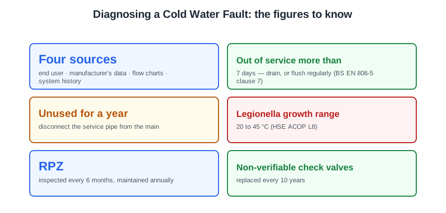
- Four sources
- end user · manufacturer’s data · flow charts · system history
- Out of service more than
- 7 days — drain, or flush regularly (BS EN 806-5 clause 7)
- Unused for a year
- disconnect the service pipe from the main
- Legionella growth range
- 20 to 45 °C (HSE ACOP L8)
- RPZ
- inspected every 6 months, maintained annually
- Non-verifiable check valves
- replaced every 10 years
- Water softener
- inspected every 2 months, maintained every 6
- Booster start-up limit
- pressure must not fall more than 50%, nor below 1 bar
- Booster shut-down limit
- rise not more than 100 kPa above permissible operating pressure
⚠️ Where people go wrong
- Asking the customer for technical readings. They give you the history — when, how often, what noise, what they already tried.
- Swapping a component on a hunch before opening the manufacturer’s literature. The flow chart is in the O&M instructions, not the brochure.
- Checking the impeller when the motor will not turn at all. A motor that does not run is an electrical fault first.
- Draining without admitting air. Check valves hold a vacuum and a cylinder can collapse.
- Blaming blue water on dissimilar metals. It is infrequent use of copper, and flushing clears it.
- Quoting pH as a cause of low flow. It has no direct effect — length, roughness and fittings do.
- Leaving a disconnected appliance’s pipework in place. It must be cut back at its source, or it is a dead leg.
📝 10-Question Self-Test
Straight from the Level 3 course question bank. Click an option to see whether you got it right — the explanation appears instantly, and there is nothing to submit.
The person living with the system saw it happen, and they are the first source of the immediate history: when it started, whether it is constant or intermittent, any unusual noises, and whether anyone has already tried a repair. The manufacturer’s helpline knows the appliance but has not seen this one, and cannot say what changed last week.
Pump maintenance intervals and tasks are set by the manufacturer and vary by model. Fixed generic intervals are wrong for a sealed unit that still needs strainers and seals checking.
Every open end must be capped so that nothing can enter the pipework and no water can escape if the supply is restored unexpectedly. Nothing short of capping makes the system safe.
A defective fitting is one the Regulations say must not be used; the remedy is to replace it. Anything short of replacement leaves the fault in place.
Talking it through with the customer, face to face or on the phone, is how you get the immediate history of the fault and then ask the follow-up questions that narrow it down. A schematic shows how the system was built and a commissioning certificate shows how it performed on day one; neither tells you what has changed since.
A diagnostics flow diagram takes the checks in order, one question per box, starting with the cheapest and most likely cause, so you are not guessing on a component with many parts that could have failed. The warranty card and the parts price list matter once you know what has failed; they are no help in finding it.
The safe order starts by isolating the supply, then labelling the isolation point so nobody turns it back on, leaving contact details, and capping the open ends. Any sequence that caps or drains before isolating is wrong.
Blue water is copper dissolving from new copper pipe into water left standing in it, staining fittings blue-green. It is prevented by flushing new copper installations thoroughly so the protective oxide film can form.
What the end user is placed to give you is the immediate history: when the fault started, how they noticed it, whether it is constant or intermittent, any unusual noises, and whether they have attempted a repair. Pressure readings, pipe sizes and valve settings are things you go and measure or look up; do not expect them from the customer.
BS EN 806-5 covers operation and maintenance, and its clause 9 lists what to check when something goes wrong: stop valves not fully open, blocked filters and spray outlets, defective pressure reducing valves, scaling and water hammer. BS 7671 is the electrical wiring regulations and BS EN 1057 is the copper tube specification, so neither diagnoses a water fault.
Going further: the lessons behind this article
This article is the public answer. Unit 331 of the Level 3 course takes the same ground to the depth the exam and the synoptic assignment ask for, in 4 lessons:
- Sources of fault information: the end user and the manufacturer
- System history: commissioning records, logbooks and inspection frequencies
- Isolation: required valves and the isolate, label, cap-off sequence
- Draining down, standing water and diagnostic readings
- Cold water systems: the Unit 331 guide — every article on this unit in one place
- All PlumbMate articles — Level 1, 2 and 3
- The Level 3 course — the whole 8202-35 Diploma