A site meeting. The architect has the drawings, the electrician has BS 7671, the surveyor has the bill of quantities, and somebody asks who is bringing the Water Regulations Guide. The answer is the plumber — because the duty falls on whoever installs the fitting, not on whoever drew it.
The short answer
Two things are law: the Water Supply (Water Fittings) Regulations 1999, and the Building Regulations. Everything else is recommendation — and following it is the accepted way of showing the law has been met.
Design guidance for cold water systems inside buildings is BS EN 806, in five parts, with BS 8558:2015 as the UK complementary guidance alongside it. Commissioning procedures are in BS EN 806-4, section 6. Those two answers are worth fixing in memory, because the exam offers BS 7671 (wiring) and BS EN 12056 (drainage) alongside them to catch anyone picking a familiar number.
Regulation 3, and the design rule that follows from it
Regulation 3 forbids any fitting installed, connected, arranged or used so that it causes or is likely to cause waste, misuse, undue consumption, contamination or erroneous measurement.
Almost everything in cold water design is Regulation 3 wearing different clothes. Servicing valves deal with waste, because a dripping float valve can be isolated. Avoiding dead legs deals with contamination. Limiting run-off at outlets deals with undue consumption.
Which gives the rule that matters most: lay the system out so those harms cannot arise, and only then add devices such as check valves where the layout alone cannot do the job. Designing the layout first and the devices second is not a style preference — it is what a device-heavy design is admitting it got wrong.
And Regulation 5 notification is part of the design work, not an afterthought for the office. If your design includes a booster over 12 l/min, a bath over 230 litres, an RPZ or a pipe outside the 750 to 1,350 mm depth band, the notice is a design deliverable.
What each standard actually gives you
- BS EN 806-1 — general. Terms and definitions used by all five parts.
- BS EN 806-2 — design. System design; clause 19.1 storage cisterns and recommended storage capacities.
- BS EN 806-3 — pipe sizing. The simplified method: Table 2 draw-off flow rates and loading units, Table 3 pipe sizes per material, pressure and velocity limits.
- BS EN 806-4 — installation, filling, flushing; commissioning and pressure testing in section 6.
- BS EN 806-5 — operation and maintenance. Tasks and intervals.
- BS 8558:2015 — UK guidance alongside: Table 5 design flow rates, Annex A boosted systems, Annex C traditional UK loading units and the tabular sizing method, and the backflow protection tables.
- BS 6700 — withdrawn, but you will still meet its figures in older drawings and exam questions. Use it for method, and say when a figure has been replaced.
Around them sit BS 8000-15 (workmanship), BS 1710 (pipe identification colours), PD 855468 (flushing and disinfection) and HSE ACOP L8 (control of Legionella).
The manufacturer beats the standard
Standards give general figures; the manufacturer gives the figures for the appliance you are actually fitting. BS EN 806-3 Table 2 gives a shower head a flow rate — and also says to check with the manufacturer for non-domestic appliances. BS 8558 Table 5 says the choice of outlet fitting affects the flow delivered, and manufacturer's advice should be obtained.
When commissioning a mechanical component — a pump, a PRV, an accumulator — it is the manufacturer's instructions you consult, not a price list, the client's brief or the risk assessment. Ignoring them voids the warranty and can put you in breach of the Regulations without knowing it.
Two documents both carry the performance requirements: the installation specification says what the system must achieve, and the manufacturers' technical data says what each appliance needs in order to achieve it.
Which plan answers which question
A new estate, thirty plots, and you need to know where each dwelling's boundary stop valve will be. The architect hands over a roll of drawings, and picking the wrong one wastes the morning.
| Plan | Typical scale | What you take from it |
|---|---|---|
| Block plan | smaller than a site plan | Where the site sits among neighbouring buildings and roads. Too small to locate a stop valve. |
| Site plan | 1:500 or 1:1000 | The building on its plot: the incoming main, the boundary stop valve for each dwelling, drains, external runs. |
| Floor plan | 1:100 or 1:50 | Room layout, wall thicknesses, appliance positions, horizontal runs. With the bill of quantities, the pair used for costing. |
| Part plan / detail | 1:20, 1:10, 1:5 | A bathroom or plant area in detail. |
The scale is a ratio. At 1:100, 10 mm on paper is 1 m in the building. At 1:50, 10 mm is 500 mm. At 1:500, 10 mm is 5 m. The smaller the second number, the larger the drawing and the more detail it carries.
Heights come from somewhere else
The floor plan gives you the horizontal run to the bathroom. The pipe also has to climb, and no plan can tell you how far, because a plan looks straight down.
An elevation is a view of one face of the building, so a side elevation gives the height of a storey, an eaves or a cistern platform. A section cuts through and shows floor-to-floor heights and the loft. A schematic or isometric shows the pipework itself with every junction, valve and appliance — usually not to scale, though it is good practice, from the withdrawn BS 6700 (Annex D), for the isometric used for pipe sizing to be drawn to scale, with each junction numbered for the calculation sheet.
To measure off a scale drawing: lay it flat, read the scale from the legend in the title block, pick the matching edge of the scale rule, put the zero on the start of the line and read the length. The commonest error is reading the wrong edge, because most rules carry two scales on each edge.
No drawings? Measure it, and pick the right instrument
An existing 1930s semi, a new bathroom, no drawings in the house. Even on a new build the drawing and the building do not always agree, so measurements are taken in situ, in this order of accuracy:
- Laser measure — the most accurate, about ±3 mm, one person, unaffected by sag or obstacles.
- Measuring wheel — for long external runs; more accurate than pacing, a folding rule or scaling off a plan.
- Tape measure — needs two people, and reads long if it sags or bends round an obstruction.
- Ultrasonic measure — quick, but thrown by obstructions.
Write down every section length as you go, because those lengths become the rows of the calculation sheet, and a length guessed later is a pipe sized wrong.
While you are in the building, survey what the pipes pass through and what the appliances hang on. A wall-hung basin on a timber stud partition needs a timber fixing board; solid brick, block or concrete take fixings directly. Find out which wall before the quotation goes in, not after the basin is in the van.
And look at where the customer wants the cold main to run. Routing it through the airing cupboard beside a hot flow and return is a design fault, not an insulation problem — BS 8558 clause 4.3.5.1.1 says cold water should not be warmed above 25 °C and ideally not above 20 °C, and no thickness of lagging guarantees that in a warm cupboard. Re-route it, then measure the route you will actually use.
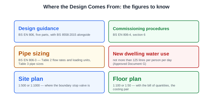
🔢 The numbers worth memorising
- Design guidance
- BS EN 806, five parts, with BS 8558:2015 alongside
- Commissioning procedures
- BS EN 806-4, section 6
- Pipe sizing
- BS EN 806-3 — Table 2 flow rates and loading units, Table 3 pipe sizes
- New dwelling water use
- not more than 125 litres per person per day (Approved Document G)
- Site plan
- 1:500 or 1:1000 — where the boundary stop valve is
- Floor plan
- 1:100 or 1:50 — with the bill of quantities, the costing pair
- Reading a scale
- at 1:50, 10 mm = 500 mm; at 1:100, 10 mm = 1 m; at 1:500, 10 mm = 5 m
- Laser measure accuracy
- about ±3 mm — the most accurate on site
- Cold water temperature
- not above 25 °C, ideally not above 20 °C (BS 8558 4.3.5.1.1)
⚠️ Where people go wrong
- Treating a British Standard as law. The Regulations are the law; the standard is how you show you met them.
- Choosing BS 7671 or BS EN 12056 for cold water design. One is wiring and one is drainage — both sit in the answer list as distractors.
- Looking for a boundary stop valve on a block plan. It is too small a scale; the site plan has it.
- Trying to get a height off a plan. A plan looks straight down — heights come from an elevation or a section.
- Reading the wrong edge of the scale rule. Most rules carry two scales per edge, and the mistake is invisible until the pipe is cut.
- Lagging a cold main through an airing cupboard. That is a re-route, not an insulation problem.
- Leaving notification to the office. If the design includes a notifiable fitting, the notice is part of the design.
📝 10-Question Self-Test
Straight from the Level 3 course question bank. Click an option to see whether you got it right — the explanation appears instantly, and there is nothing to submit.
The Regulations apply to whoever installs the fittings, so the plumber doing the work is the one who must consult the Guide; the others are not installing anything.
Of the four, only the measuring wheel is rolled along the actual line and counts it off, so it beats pacing, a one-metre rule walked end over end, and scaling off a plan, each of which piles up an error at every step. Scaling from the site plan is the tempting one, but it gives you what was drawn, not what was built.
A site plan shows the building on its plot, typically at 1:500 or 1:1000, with the incoming main, the drains and the external runs, so each dwelling’s boundary stop valve position is read from it. A block plan only places the site among neighbouring buildings and roads, and is drawn far too small to locate a stop valve.
The water undertaker will state the mains pressure for the area, and it can be measured on site with a gauge at the first supply-pipe outlet, the kitchen sink tap. The council holds no such data and cistern-fed outlets only show cistern head.
The water supplier holds the data on mains pressure and flow at peak times and must be consulted at the design stage; permission is also needed from them for any pump drawing more than 12 l/min.
Flow rate is a volume in a time, so it is measured as one: a weir gauge or any vessel of known volume, timed. Pressure is a different quantity and a high static pressure tells you nothing about what the outlet will actually deliver, because the moment the tap opens the pressure falls. Bore alone gives no rate either, since the flow depends on the head and the resistance of the whole run.
The installation specification says what the finished system must achieve, and the manufacturers’ technical data gives the flow rate and working pressure each appliance needs in order to achieve it. Between them they set the performance requirements. A risk assessment and method statement cover how the work is done safely, not how the system must perform.
BS 4213 is the product specification for thermoplastic cold water storage and feed and expansion cisterns up to 500 litres. It is about cisterns, and contains nothing on sizing pipes.
A pump’s output depends on its own impeller and motor, so the flow and pressure it will give at a particular head come from the maker’s performance curve, and BS EN 806-5 requires booster pumps to be serviced and set to the manufacturer’s instructions. BS EN 806-3 sizes pipework by loading units; it says nothing about what any one pump delivers.
Pump duty is matched from the maker’s own performance curves, which plot the flow a pump gives against the head it has to develop; only those curves tell you whether a given pump will deliver your calculated flow at your calculated head. BS EN 806-5 sends you to the manufacturer for booster pumps. BS 8558 helps you work the demand out, but lists no pump models.
Going further: the lessons behind this article
This article is the public answer. Unit 331 of the Level 3 course takes the same ground to the depth the exam and the synoptic assignment ask for, in 3 lessons:
- Design information: the Regulations, notification and BS EN 806
- Design information: manufacturer data, customer feedback and scale plans
- Reading drawings: elevations, sections, specifications and site surveys
- Cold water systems: the Unit 331 guide — every article on this unit in one place
- All PlumbMate articles — Level 1, 2 and 3
- The Level 3 course — the whole 8202-35 Diploma