A gauge that has to be tapped is a fitting that has failed. The caretaker tapped it every morning, which is why nobody noticed for months that the set was losing pressure.
The short answer
Regulation 3(3) says no fitting may be installed, arranged or used which, by being damaged, worn or otherwise faulty, causes or is likely to cause waste, misuse, undue consumption or contamination. Regulation 4(5) requires every fitting to be installed, altered, repaired or disconnected in a workmanlike manner.
So when an inspection finds a defective fitting, the answer is to replace it — not wrap it, monitor it, or note it and leave it. Fit like-for-like wherever you can, with the manufacturer's own spares, so the component performs as designed and its approvals are unaffected.
Gauges, PRVs and control panels
Bourdon gauges are fitted on the inlet and outlet of a boosted pump set so its performance can be read. A gauge that disagrees with a calibrated test gauge, or whose needle sticks, is replaced — not tapped, lubricated or reset to zero. A gauge is cheap and the decisions made on its reading are not.
A pressure reducing valve controls its outlet by back-pressure acting across the whole area of a diaphragm. BS EN 806-5 Annex B.18: clean or replace the strainer, inspect the internals, then check the outlet pressure at zero flow and at peak flow. Both — because a valve that holds its setting with nothing running has not yet been tested under load.
Pump faults: which side of the line?
The new gauge showed the next fault within a week: the duty pump humming, the discharge gauge not moving, everything above the second floor dry. Pump faults split into electrical and mechanical, and the first job is deciding which.
Electrical. If the motor does not run, check supply and breakers first. A breaker that keeps tripping means testing the wiring and the motor. On a single-phase pump a failed capacitor is common: isolate, discharge it, test with an ohmmeter, replace if it fails. Motor winding resistance is tested with a low resistance ohmmeter across the disconnected leads after safe isolation, compared with the manufacturer's chart — a low reading suggests a winding shorting, a high one a winding going open. Running current above the manufacturer's figure, read with a clip-on ammeter, shows up loose connections, a shorted winding, burned starter contacts or a damaged pump.
Mechanical. The humming pump passes every electrical test, which is itself the answer: a pump that runs but moves no water, leaving the outlets dry, most probably has a broken impeller shaft. The motor turns; the impeller does not.
A pump that runs with poor flow rather than none may be rotating the wrong way (re-wire), be air-locked (prime through the priming plug, opening the suction valve first), or be starved by clogged strainers and check valves (clean them).
Whatever the repair, prove it with readings: a fall on the suction gauge and a rise on the discharge gauge to the data plate figure, running current and winding resistance within the manufacturer's data, no unusual noise or vibration. Then check the flow rate against the commissioning figures and record it.
Booster set controls: the vessel and the switches
A set that used to start a few times an hour now starts every time someone washes their hands. Nothing is leaking. Two components share the blame.
The accumulator. Its repair is nearly always the air pre-charge, checked at the Schrader valve with the water side isolated and depressurised. Pre-charge is 80–90 per cent of the pump cut-in pressure: a 2 bar cut-in gives 1.8 bar. It must also sit below the supply pressure or water cannot enter. Top up a low charge with a foot pump or compressor. If water comes out of the Schrader valve, the bladder has ruptured and the vessel is replaced. If the vessel is simply too small for the pump's flow, it is replaced with a larger one.
To protect it, the accumulator's supply should carry a strainer, a check valve and a pressure reducing valve — grit off the diaphragm, stored water out of the supply, and the inlet below the vessel's rated pressure.
The pressure switch or transducer starts and stops the set on low and high pressure. Check it against a calibrated gauge on the pipework; a failed transducer often reads over 12 bar whatever the true pressure. A switch out of adjustment is reset; a defective one is replaced.
On the cycling set the transducer agreed with the test gauge and the Schrader valve showed almost no charge. Pumped back to 1.8 bar, it went back to starting a few times an hour. Had the pressure been decaying with no draw-off, the suspects would have been a leak or a non-return valve passing back to the suction side.
The float switch is tested by moving the float arm by hand and confirming the pump or solenoid responds at the on position and again at off. A switch that does not change state is replaced as a unit, with its levels put back to the commissioning figures.
Faults on the set as a whole
| Fault | Cause | Repair |
|---|---|---|
| Water circulating through the standby pump while the duty runs | Non-return valve on the standby discharge passing | Replace the check valve |
| Duty pump running, draw-offs dry | Impeller not rotating (broken shaft or coupling) | Replace the pump or impeller assembly |
| Pumps cycling too often | Pressure switch faulty, accumulator too small or pre-charge lost | Reset or replace the switch, recharge or upsize the vessel |
| Set will not start | Loss of supply, or dry-run protection from the float switch | Restore supply, restore cistern level, check the float switch |
The first line is the one to feel for: a standby pump warm when it has not run for a week. Its non-return valve has failed, so part of the duty pump's output circles through the idle pump instead of reaching the outlets. Replace the check valve — do not run both pumps to make up the difference.
And check the panel rotates the duty, so no pump stands idle and stagnates.
Testing backflow devices
A double check valve on a garden irrigation supply has been there eight years and nobody has looked at it. If it is passing, nobody will know until the day the mains pressure drops.
The safe test is to simulate a loss of upstream pressure and see whether the device holds. On a verifiable single or double check valve (EA, EC), the test point makes this possible: with the downstream side under pressure and no flow, close the upstream valve and open the upstream test outlet. Flow must stop once the pipe has emptied — if it continues, the valve is passing and is replaced as a precaution.
Non-verifiable valves (EB, ED) have no test point. There is nothing to open and watch, so they are simply replaced every 10 years. Our eight-year-old irrigation valve, if it has no test point, is two years from its date however sound it looks.
A type CA device is tested by closing the upstream stop valve and checking that nothing discharges. A hose union backflow preventer (HA) is tested by filling a hose from the tap, closing it, and checking that the hose drains.
And the rule that outranks the customer's convenience: bypassing a backflow device, even briefly, is prohibited. A temporary link round a check valve to keep the garden going is exactly the connection the device exists to prevent. While a device is out of action, the supply it protects is isolated.
Reading the RPZ
The RPZ (type BA) is maintained by cleaning the strainer, testing the check valves, seals and discharge port, cleaning the air break to drain, testing the static, dynamic and differential pressures at its three test points (BS EN 806-5 Annex B.3), and recording the results. Inspected every 6 months, maintained once a year.
A relief port that keeps dripping is the valve telling you something: a failed upstream check lets the middle chamber equalise with the mains and the relief valve discharges continuously; a ruptured diaphragm also passes water to the port. Also check the type AA air gap below the relief port, and that the downstream use has not changed to a higher fluid category since the valve was chosen.
If an RPZ malfunctions, the owner is told immediately and the supply upstream is isolated until it is repaired. Only a plumber approved and certificated through WRAS may test, service or replace one. If that is not you, your job ends at diagnosis and the call to the owner.
One more RPZ symptom worth having: a hotel whose top-floor showers have lost pressure gradually over months, with the booster set testing fine, is usually cured by cleaning the line strainer immediately upstream of the RPZ.
Galvanic corrosion
A compression fitting in a cellar has a crust of white powder on it and the brass under the crust has gone pink. It weeps, and when gripped with a spanner it cracks.
Electrolytic (galvanic) corrosion occurs when two dissimilar metals are in electrical contact in the presence of an electrolyte — and water is an electrolyte. A small current flows; the more noble metal is the cathode and is unharmed, the less noble is the anode and is eaten away. The further apart in the electrochemical series, the faster: copper at +0.15 V against zinc at −0.76 V is why ordinary brass, a copper-zinc alloy, loses its zinc.
The three diagnostic signs are exactly what the cellar showed: white powdery zinc oxide on a brass fitting, yellow brass turning reddish, and fittings going brittle and cracking.
Schedule 2 paragraph 3 requires every fitting to be immune to or protected from corrosion by galvanic action, so the repair is a fitting of gunmetal or dezincification-resistant brass, marked CR (or DRA). Copper, copper alloys and stainless steel can be mixed safely; copper to galvanised steel, and brass fittings onto old lead pipe, need protection. And when you replace a length of metal pipe, BS EN 806-5 clause 10 requires earthing continuity to be maintained across the repair.
The seven steps
Every repair, from a float valve washer to a booster pump, follows the same shape. Miss a step and something is left behind — an unlabelled valve, an untested joint, a customer who does not know where the stopvalve is.
- Diagnosis — gather the history, apply the checks, and confirm the fault by measurement before ordering a part.
- Notifying the client — what is wrong, what you propose, the cost, and which part of the system will be off and for how long. Agreement before starting. (BS EN 806-5 Annex B.3 requires the owner to be told immediately if a backflow device has failed.)
- Safely isolating — water at the nearest valve; electricity at the isolator, proved dead and locked off; labels and a Do Not Use notice with your contact details.
- Decommissioning — relieve the pressure, drain with air admitted, cap open ends. Where a component is removed permanently, cut the pipe back to the live main so no dead leg is left.
- Rectifying — like-for-like or the manufacturer's spare, in a workmanlike manner.
- Re-commissioning — refill, vent, flush, test, disinfect where needed, re-check against the record.
- Handing over — walk the customer round, explain the working principles of the controls, show the isolation points, and give them the literature and a fully completed and signed commissioning record. Record the repair in the logbook.
Bringing the water back has two rules inside it that the exam looks for. Refill by partially opening the stop valves, starting with the service stop valve, venting the pipes completely by slowly opening the taps to prevent pressure surges, then fully opening and flushing. And where pipework has been altered, pressure test it — Schedule 2 paragraph 12 requires the system to withstand 1.5 times the maximum working pressure, and a large pressure drop means find and rectify the leak and re-test. Never top up and carry on.
After a short interruption it is usually enough to open each draw-off for about 5 minutes to run off stagnant water (BS EN 806-5 clause 8).
🔢 The numbers worth memorising
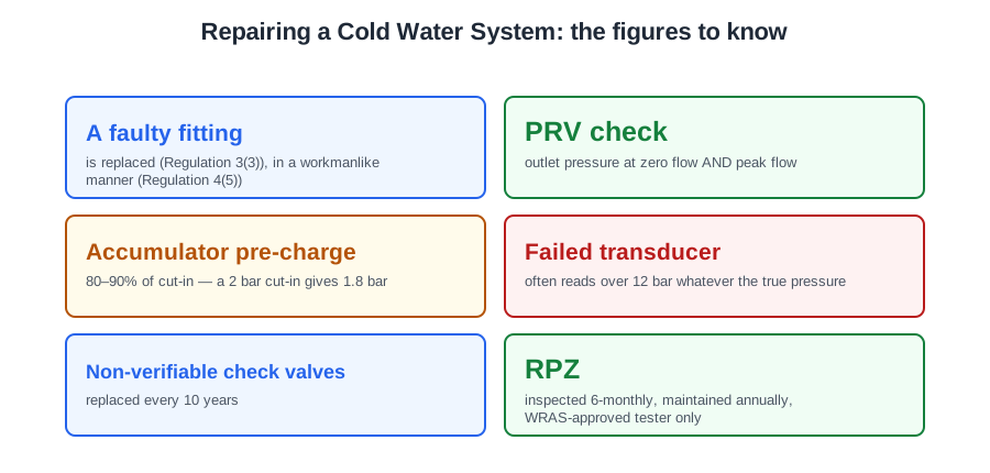
- A faulty fitting
- is replaced (Regulation 3(3)), in a workmanlike manner (Regulation 4(5))
- PRV check
- outlet pressure at zero flow AND peak flow
- Accumulator pre-charge
- 80–90% of cut-in — a 2 bar cut-in gives 1.8 bar
- Failed transducer
- often reads over 12 bar whatever the true pressure
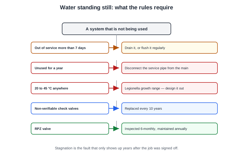
- Non-verifiable check valves
- replaced every 10 years
- RPZ
- inspected 6-monthly, maintained annually, WRAS-approved tester only
- Galvanic pair
- copper +0.15 V against zinc −0.76 V
- DZR marking
- CR (or DRA)
- Pressure test
- 1.5 × maximum working pressure (Schedule 2 paragraph 12)
- After a short interruption
- run each draw-off for about 5 minutes
⚠️ Where people go wrong
- Tapping, lubricating or re-zeroing a sticking gauge. It is replaced.
- Checking a PRV at no flow only. It has to hold its setting under load as well.
- Chasing electrics on a pump that runs but delivers nothing. That is a broken impeller shaft.
- Running both pumps to make up for a warm standby. Its non-return valve has failed — replace it.
- Bypassing a backflow device “just for today”. Prohibited, even briefly.
- Capping an RPZ relief drip. It means the first check valve is leaking.
- Blaming a corroded brass fitting on water quality. White powder, pink brass and cracking is galvanic — replace with gunmetal or CR-marked DZR.
- Topping up after a pressure-test drop. Find the leak, rectify it, and re-test.
📝 10-Question Self-Test
Straight from the Level 3 course question bank. Click an option to see whether you got it right — the explanation appears instantly, and there is nothing to submit.
A boosted installation carries pressure gauges either side of the pumps so their performance can be read; the standard boosted layouts show the gauge on the pump set.
A pressure switch or transducer on the pump discharge senses the fall in pressure when outlets open and starts the pumps, and stops them when the pressure recovers.
No British Standard describes blue water corrosion; the usual trade account is that copper dissolves into water left standing in new pipework before a protective film has formed, helped by flux residue in the bore. What the standard does require is regular water movement: BS 8558 clause 5.2.3.1 has every new service thoroughly flushed before it goes into service, to remove debris and organic matter that encourage biofilms, and clause 5.2.3.2 has systems left unused for up to 30 days during construction re-flushed. A softener changes the hardness, not the stagnation that causes the problem.
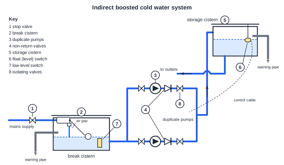
The float (level) switch in the high-level storage cistern, number 6, calls the pumps when the level falls and stops them when it is restored. Number 3 is the pumps themselves, 4 the non-return valves and 1 the stop valve.
Water hammer is the pressure surge when moving water is stopped suddenly. A shock arrestor (a small air- or gas-charged vessel) close to the offending valve absorbs the surge.
The RPZ Approved Installation Method (AIM 08-01, January 2020 issue) at 5.3 allows an RPZ valve to be commissioned and compliance tested only by a person recognised by a water undertaker as having gained a recognised qualification in RPZ valve commissioning and testing from a recognised training provider, who is either a member of a scheme for RPZ testers recognised by the water industry, that is a water undertaker approved contractor scheme or WaterSafe, or recognised by the undertaker on a site by site basis. The valve is compliance tested at least annually (5.9) and again after any repair or dismantling, and the test report goes to the water undertaker within ten working days. A Level 2 qualification, or any general plumbing qualification, does not cover it: the recognition is separate and held for this device. WRAS only publishes the list of approved contractor schemes; it is not the approving body.
A verifiable check valve, types EA and EC, carries a test point. With the downstream side under pressure and no flow, close the upstream valve and open the test outlet: once the pipe has emptied the flow must stop, or the valve is passing and gets replaced. A strainer only catches debris and tells you nothing about whether the valve seals.
Dezincification-resistant brass is stamped CR, and gunmetal is the other safe choice where the water is aggressive; Schedule 2 paragraph 3 requires fittings to be immune to or protected from galvanic corrosion. DR looks like the obvious abbreviation of dezincification-resistant, but the mark you look for on the fitting itself is CR.
Take a sample of the raw supply and one of the softened water and compare their hardness, with titration drops or a hardness test strip. That is the direct check, and it is what a manufacturer’s commissioning sheet asks for. pH indicator strips are the trap, and older material gives them as the answer: an ion-exchange softener exchanges calcium and magnesium for sodium and leaves the alkalinity where it was, so the pH barely moves whether the unit is working or has run out of salt. A refractometer reads glycol strength and a thermometer reads temperature; neither says anything about hardness.
With the duty pump running, the only route for water into the idle standby pump is backwards from the discharge manifold, and the non-return valve on the standby's discharge is what should stop it. If that check valve is passing, the duty pump's output recirculates through the standby back to the suction side and the draw-offs starve. The standby's isolating valves are open in normal service so it can start on demand; closing one would stop the recirculation, not cause it, and closing a valve on the running pump would deadhead it, a different fault.
Going further: the lessons behind this article
This article is the public answer. Unit 331 of the Level 3 course takes the same ground to the depth the exam and the synoptic assignment ask for, in 4 lessons:
- Replacing faulty fittings: gauges, pressure reducing valves and pumps
- Booster set controls: accumulator, pressure switch and float switch
- Backflow devices: testing check valves and maintaining the RPZ valve
- Galvanic corrosion and the seven steps to handover
- Cold water systems: the Unit 331 guide — every article on this unit in one place
- All PlumbMate articles — Level 1, 2 and 3
- The Level 3 course — the whole 8202-35 Diploma