Two figures decide whether the top-floor shower will ever work, and no drawing gives either of them. Both are measured on site, before the calculation starts.
The short answer
Strip away every design factor and one question is left: what flow does the installation require, against what the supply can deliver? Every other decision follows from the gap between those two numbers.
So the sizing runs in one direction: measure what the supply gives → count the loading units the building wants → pick a pipe size from the table → and where the supply cannot meet the demand, add a pump or an accumulator.
Measuring what the supply gives
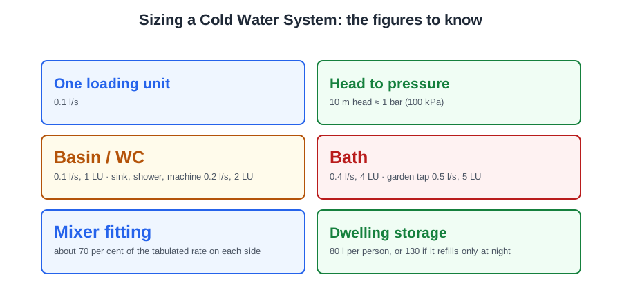
For a cistern-fed system, the pressure available at an outlet is the vertical distance from the base of the cistern to the outlet (the older BS 6700 method took it from the cistern outlet). Pressure is expressed as head: 10 m of head is roughly 1 bar (100 kPa).
For a mains-fed system the figure is the minimum pressure at peak demand, read with a pressure gauge on an outside tap at a busy time of day, or obtained from the undertaker. A reading taken at a quiet time flatters the main and the shower pays for it later.
The second figure is the flow rate, measured with a weir gauge: water escapes through a slot in the side and the height it reaches reads the flow. A weir gauge reads flow rate and nothing else — not pressure loss, not head loss, not diameter — and excessive flow spills over the top and gives a false reading, so use a flow meter on a strong supply.
Putting the measurements together. A 1:50 floor plan shows the cold supply to a bathroom as a line 184 mm long: 184 × 50 = 9,200 mm, so 9.2 m horizontally. The section shows the bathroom floor 2.7 m above the stop valve. The actual pipe length is 9.2 + 2.7 = 11.9 m, which sets the friction loss — and the 2.7 m rise is deducted from the available head, because the water has to climb it before it reaches the tap. The rise gets counted twice, for two different reasons, and that is the step people miss.
Loading units
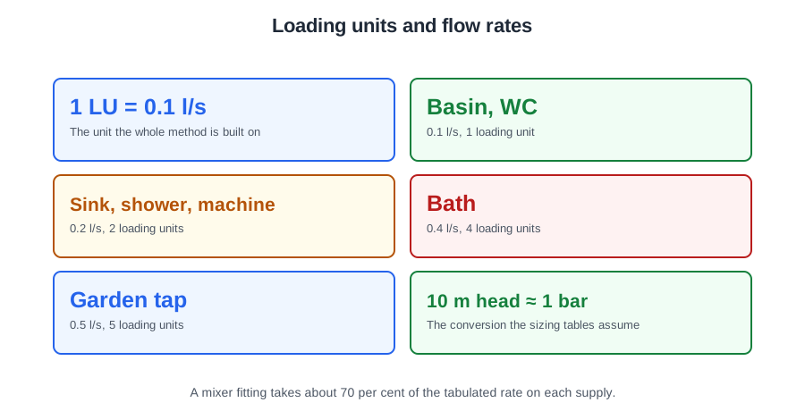
Three related figures. The design flow rate is what an outlet should get when it is the only one discharging. The minimum flow rate is what it must still get when other outlets are in simultaneous use. A loading unit (LU) is a number given to an appliance allowing for its flow rate, how long it runs and how often it is used — and one loading unit equals 0.1 l/s.
| Draw-off point | Design flow | Minimum | LU |
|---|---|---|---|
| Washbasin, handbasin, bidet, WC cistern | 0.1 l/s | 0.1 l/s | 1 |
| Kitchen sink, washing machine, dishwasher, shower head | 0.2 l/s | 0.15 l/s | 2 |
| Urinal flush valve | 0.3 l/s | 0.15 l/s | 3 |
| Bath (domestic) | 0.4 l/s | 0.3 l/s | 4 |
| Garden or garage tap | 0.5 l/s | 0.4 l/s | 5 |
Older material and BS 8558 Table 5 carry the BS 6700 figures instead (WC 0.13, basin 0.15, bath 0.30, sink 0.20). If a question asks for the design flow rates used for pipe sizing, give the BS EN 806-3 set.
One refinement: where a mixer is fed from both hot and cold, the demand is shared, so about 70 per cent of the tabulated rate is allowed on each side. Adding the hot and cold loading units together oversizes the pipe (BS 8558 clause 4.3.30).
Cistern storage
BS EN 806-2 clause 19.1.4: for a dwelling with a constant supply at adequate pressure, a maximum of 80 litres per person normally resident should prove satisfactory; where the cistern refills only at night, base it on 130 litres per person. Table 6 covers other buildings — hostel 90 l per bed, hotel 200 l per bed, office 45 l per employee, primary school 15 l per pupil.
Two rules of thumb from the withdrawn BS 6700 are still asked for: a cistern feeding only the hot water cylinder must hold at least the capacity of the cylinder; one feeding both cold outlets and the cylinder must hold at least 230 litres.
And the constraint that pulls the other way: do not oversize. BS EN 806-2 says water must be held in storage for as short a time as possible to prevent stagnation.
A four-person house: 4 × 80 = 320 litres, comfortably above the 230 litre minimum for a cistern serving both. Night-only refilling would give 520.
The copper table, worked
BS EN 806-3 Table 3.2 for copper reads like this:
| Copper tube | Maximum load | Highest single appliance | Maximum length |
|---|---|---|---|
| 12 mm | 1 / 2 / 3 LU | 2 LU | 20 m / 7 m / 5 m |
| 15 mm | 3 / 4 / 6 LU | 4 LU | 15 m / 9 m / 7 m |
| 18 mm | 10 LU | 5 LU | no limit |
| 22 mm | 20 LU | 8 LU | no limit |
| 28 mm | 50 LU | — | no limit |
Read the small sizes with their length limits: 15 mm carries 4 LU only up to 9 m, and 6 LU only up to 7 m. The "highest single appliance" column stops a bath (4 LU) being fed through a size that only allows a 2 LU appliance. Going up a size is always permitted.
The worked house. Bath (4), shower (2), basin (1), WC (1), kitchen sink (2), washing machine (2) — 12 LU in total. Work back from the furthest outlet:
- The pipe to the bath alone: 4 LU over 3 m. The 15 mm column allows 4 LU up to 9 m → 15 mm.
- The WC and basin branch: 2 LU → 15 mm.
- The bathroom branch: 4 + 2 + 1 + 1 = 8 LU, highest single 4. The table gives 18 mm (10 LU, highest 5) — but 18 mm is not a stocked UK size, so take the next size, 22 mm.
- The supply pipe from the stop valve: all 12 LU. 18 mm is limited to 10, so 22 mm (20 LU, highest single 8).
Where a section also feeds a storage cistern, add the cistern refill flow to that section.
Notice what never entered the calculation: the number of bends, the insulation, the warning pipe. Only the loading units each section carries, the length for the small sizes, and the biggest single appliance on the run. Three numbers per section.
When the main falls short: the pump
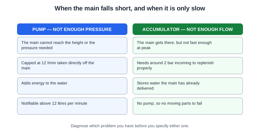
The table sizes the pipe; it cannot make the main deliver. In a dwelling the pump normally draws direct from the supply pipe, which BS 8558 Annex A.4 permits where the pumped rate is not more than 0.2 l/s (12 litres per minute). Anything larger needs the undertaker's written consent and is notifiable under Regulation 5 — the same 12 l/min figure from the notification list, seen from the other end.
The pump head must cover three things (BS 8558 Annex A.6): the static lift + the friction losses + the residual pressure the appliance needs. Miss any of the three and the shower runs weak.
Worked example. The shower needs 0.2 l/s at 100 kPa (10 m head). Static lift 4 m, friction losses 3 m. Total head = 4 + 3 + 10 = 17 m.
Hydraulic power = flow × 9.81 × head = 0.2 × 9.81 × 17 = 33 W; at 60 per cent efficiency the motor must supply about 56 W.
The duty point is 0.2 l/s at 17 m. A pump chosen for 0.2 l/s at 10 m — the shower's own figure — would be seven metres of head short before it started.
When the main is slow rather than weak: the accumulator
Different problem: the main gives a healthy 2 bar but only 10 litres a minute, and the customer wants a 15 l/min shower. The main cannot keep up while the shower runs. The answer is not a bigger pump but a store that fills slowly and empties fast.
An accumulator is a vessel with a rubber bladder, pre-charged with air on one side and filled with water on the other. The air is compressed as water enters, so the stored water leaves under pressure without any pump running. The pre-charge must be below the incoming pressure or the vessel never fills; the usual rule is about half the supply pressure, with a PRV upstream to protect the bladder.
Worked example. Mains at 2 bar, 10 l/min. A 300 litre accumulator charged to 1 bar stores roughly half its volume — 150 litres. A 15 l/min shower runs 150 ÷ 15 = 10 minutes from store, and the main refills it in 150 ÷ 10 = 15 minutes.
So the vessel is sized on how long the biggest draw-off lasts and how long the main takes to put the water back, and the pre-charge decides how much of the vessel is actually water.
An expansion vessel looks the same and is not the same. It absorbs the growth in volume when water is heated — at least 4 per cent of the volume heated on an unvented heater — and it stores nothing for use.
Presenting the working
For buildings other than dwellings, the tabular method of BS 8558 Annex C is used instead of the simplified table: for each numbered section, convert loading units to design flow, assume a size, read head loss per metre and velocity off the pipe chart, add the equivalent length of fittings, and check that the residual head at the end of the section is at least what the tap needs. If not, go up a size and repeat.
Present it the way the withdrawn BS 6700 (Annex D) set out, which is still the practice: a line drawing with every junction numbered from the source, and a calculation sheet with a row per section giving loading units, design flow, pipe size, velocity, head loss, lengths, available and residual head. The numbers on the drawing are the row numbers on the sheet, so a reader can put a finger on any pipe and find its working.
What goes out depends on who reads it. A householder's quotation gets a simple sketch with the sizes marked. A tender gets the calculation sheet with scale drawings, the specification and a bill of quantities. Same twelve loading units, same 22 mm supply pipe — only the paperwork changes.
🔢 The numbers worth memorising
- One loading unit
- 0.1 l/s
- Head to pressure
- 10 m head ≈ 1 bar (100 kPa)
- Basin / WC
- 0.1 l/s, 1 LU · sink, shower, machine 0.2 l/s, 2 LU
- Bath
- 0.4 l/s, 4 LU · garden tap 0.5 l/s, 5 LU
- Mixer fitting
- about 70 per cent of the tabulated rate on each side
- Dwelling storage
- 80 l per person, or 130 if it refills only at night
- Cistern serving both
- at least 230 litres (rule of thumb, withdrawn BS 6700)
- Copper 15 mm
- 4 LU up to 9 m, 6 LU up to 7 m, highest single appliance 4 LU
- Copper 22 mm
- 20 LU, highest single 8
- Direct-boost limit
- 0.2 l/s (12 l/min) without consent
- Pump head
- static lift + friction losses + residual pressure — 4 + 3 + 10 = 17 m
- Hydraulic power
- flow × 9.81 × head, ÷ efficiency — 0.2 × 9.81 × 17 = 33 W, ≈ 56 W at 60%
- Accumulator pre-charge
- about half the supply pressure, PRV upstream
⚠️ Where people go wrong
- Counting the rise once. It adds to the pipe length for friction and subtracts from the available head — two separate effects.
- Adding a mixer’s hot and cold loading units together. About 70 per cent goes on each side, or the pipe is oversized.
- Reading the 15 mm column without its length limit. 4 LU is only good to 9 m.
- Specifying 18 mm because the table says so. It is not a stocked UK size — go to 22.
- Sizing a pump at the appliance’s own head. Add the static lift and the friction, or it is short before it starts.
- Multiplying by efficiency instead of dividing when finding motor power.
- Oversizing a cistern for “security of supply”. Standing water stagnates, and the standard says so explicitly.
- Confusing an accumulator with an expansion vessel. One stores water for use, one absorbs the growth of heated water.
📝 10-Question Self-Test
Straight from the Level 3 course question bank. Click an option to see whether you got it right — the explanation appears instantly, and there is nothing to submit.
Loading units weight each appliance for how much water it draws and how likely it is to be in use at the same time as the others. The total for everything the pipe serves converts to a design flow rate, and that with the available head fixes the size. BS EN 806-3 Table 2 gives the loading units. The number of storeys is tempting, but it affects the head available, not the flow the pipe must carry.
A larger bore carries more flow for the same pressure, and pulled bends lose far less pressure than tight elbows; the 22 mm run with pulled bends has the least resistance.
Flow rate is the cross-sectional area of the pipe multiplied by the velocity of the water: Q = A x v (m3/s = m2 x m/s).
Each fitting is converted to the length of straight pipe that would give the same head loss, and that allowance is added to the actual length to give the length used in sizing. Be aware that the standards use the words both ways: BS 8558 Annex C calls the allowance for a fitting an equivalent length added to the actual length, and the withdrawn BS 6700 called the total the effective length in its procedure while its Annex D defined equivalent pipe length as the actual length plus the allowance for fittings, which is the usage here.
Loading units are factors which take into account the flow rate at the appliance, the length of time in use and the frequency of use (BS 8558 Annex C, which carries the traditional UK method). The number of each type of appliance fed by the pipe is multiplied by its loading unit from Table C.1, and Figure C.1 converts the total to the design flow rate in litres per second; the withdrawn BS 6700 had the same chart as Figure D.1 in its Annex D.
1.0 x 0.8 x 0.7 = 0.56 m3 = 560 litres nominal. 75 per cent of that is 420 litres to the shut-off level.
Hydraulic power = mass flow x g x head = 4 x 9.81 x 30 = 1,177 W. Dividing by the 80 per cent efficiency gives 1,177 / 0.8 = 1,472 W.
A quotation only needs the client to see what is proposed and where, so a clear not-to-scale sketch is enough; full CAD is design-stage work and internet images are not the job.
An elevation is a straight-on view of one face of the building, so what you take from it are vertical dimensions: storey heights, eaves level, the height of a cistern platform. Room layout comes from the floor plan and buried drains from the site plan. Nothing under the floor shows on an elevation at all.
Fast water is noisy, it scours the bore, and it makes water hammer worse when a tap closes quickly. BS EN 806-3 bases its tables on 2.0 m/s in distribution and rising pipes and 4.0 m/s into a single fitting, where the withdrawn BS 6700 allowed 3 m/s. Low velocity does nothing to prevent freezing: that is what routing and insulation are for.
Going further: the lessons behind this article
This article is the public answer. Unit 331 of the Level 3 course takes the same ground to the depth the exam and the synoptic assignment ask for, in 4 lessons:
- Available pressure and flow, feed arrangements and loading units
- Cistern sizing, float valve refill and pipe design limits
- Pipe sizing from BS EN 806-3 tables and pump duty
- Accumulators on a weak main and the calculation sheet
- Cold water systems: the Unit 331 guide — every article on this unit in one place
- All PlumbMate articles — Level 1, 2 and 3
- The Level 3 course — the whole 8202-35 Diploma