How many floors of a twelve-storey block can the main serve on its own? About eight — and two of those are lost to friction. Everything above that is a design problem, and the undertaker will have opinions about how you solve it.
The short answer
A mains supply typically reaches a building at 3 to 7 bar, roughly 30 to 70 m head. Thirty metres lifts water about eight storeys, and friction in the pipework takes two of those back. A multi-storey building, for this purpose, is one with more than three floors.
Both BS EN 806-2 clause 15.1 and BS 8558 clause 4.3.48 give the same instruction: supply the lower floors from the main and pump only the floors where pressure is insufficient. The design question is what kind of help the upper floors get.
Direct boosting, and why suppliers dislike it
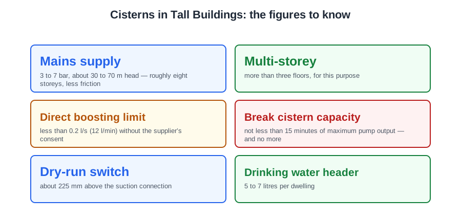
Pumps fitted straight onto the incoming supply pipe is direct boosting. It is permitted only where the pumped flow is less than 0.2 l/s (12 litres per minute) or the water supplier consents (BS 8558 Annex A.4) — and a pump drawing more than 12 l/min from a supply pipe is notifiable under Regulation 5.
Suppliers often refuse, and the reasons are good: a pump sucking on the main lowers the neighbours' pressure and raises the backflow risk. In practice direct boosting means small flows — a single top-floor flat, or a drinking water header.
Where it is allowed, something has to call the pumps. With a high-level storage cistern, a float switch starts them at about half capacity and stops them about 50 mm below float valve shut-off, so the float valve never closes against the pumps. On a mains-boosting set with no cistern, a pressure transducer on the discharge senses the fall as outlets open.
The break cistern, and what it buys you
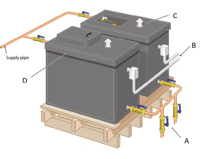
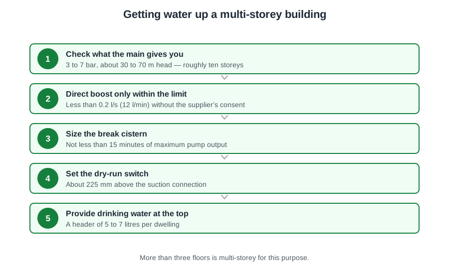
For the rest of the block the supplier will ask for the layout in BS 8558 Annex A.2: the main fills a low-level break cistern through a float valve, and a booster set on its outlet pumps to a high-level storage cistern or into the boosted supply. This is indirect boosting, and it is the usual arrangement in a tall building.
With a break cistern there is no limit on pump capacity (BS 8558 clause 4.3.9), because the pumps no longer draw on the main. Four things follow: no surge on the main when the pumps start and stop, no backflow into the main, the neighbours keep their pressure, and there is a reserve for peak demand.
In a very tall building, intermediate break cisterns on service floors split the system into pressure zones, so no floor sees more pressure than its fittings can take.
Sizing it is a balance, and the balance is the exam question. Capacity is not less than 15 minutes of the pumps' maximum output — but the cistern must not be oversized, because standing water stagnates (BS 8558 A.2). The aim is rapid turnover. A low-level dry-run switch stops the pumps at about 225 mm above the suction connection (a figure from the withdrawn BS 6700; the pump set maker’s figure governs), so the cistern is sized above that level.
Drinking water at the top of the building
BS EN 806-2 clause 19.1.2 says potable water is taken directly from the main wherever practicable. Where outlets are above the height the main can reach, the drinking taps are fed from a cistern protected in accordance with 19.1.3.
The alternative is direct boosting to a drinking water header: a pipe high in the building holding 5 to 7 litres per dwelling for the kitchen sinks while the pumps are off (BS 8558 A.5), with a pipeline level switch to start the pumps as it empties and an automatic air inlet valve on the upstand.
The 25 mm steps that decide the levels
Schedule 2 paragraph 16(4) requires every storage cistern to have an overflow pipe with a means of warning of impending overflow, screening against insects, a cover excluding light and insects, and insulation. BS EN 806-2 clause 19.1.11 then scales that with capacity:
- Up to 1,000 litres — a warning pipe and no other overflow pipe.
- 1,000 to 5,000 litres — one or more overflow pipes, the lowest of which must be a warning pipe.
- Over 5,000 litres — overflow pipes, and either a warning pipe or a level device with an audible or visual alarm in its place.
Read the stack from the water upwards and it makes sense. The warning pipe invert is at least 25 mm above the water level. The overflow invert is at least 25 mm above the warning pipe invert. So the water sits at least 50 mm below the overflow. And the inlet discharges at least twice its own diameter above the overflow, which is the type AG air gap.
BS EN 806-2 clause 19.1.8 says the same thing from the valve's side: it closes at least 25 mm below the warning pipe, or 50 mm below the lowest overflow where there is no warning pipe.
The warning pipe itself is at least 19 mm bore, rigid, never rising outside the cistern, discharging where the drip will be noticed, and able to carry the full inlet flow without submerging the inlet. Vents and overflows get corrosion-resistant mesh of 0.65 mm maximum aperture.
Filling a big cistern without hammering the main
A 10,000 litre cistern on a 6 bar main with an ordinary domestic float valve creeps open, dribbles for an hour and slams shut. Paragraph 16(1) asks for an effective adjustable valve, and a large cistern has better ways to provide one:
- Solenoid valve with float switch. No float of its own — a float switch gives the signal, and a second high-level switch shuts it if the first fails, because a solenoid stuck open sends the whole supply out of the warning pipe.
- Equilibrium valve. A hole through the piston puts pressure on both sides, so the float only lifts the arm. Nearly all valves over 54 mm work this way.
- Pressure (pilot) operated valve. A small float-operated pilot controls a diaphragm chamber that drives the main valve. Little difference between open and closed levels.
- Delayed action float valve (Keraflo, Aylesbury type). Stays shut until the level drops to a pre-set point, then opens fully. Fast fill, the water mixes rather than stratifying, no hammer, and the pumps start every few hours instead of every few minutes. Recommended in BS 8558 clause 4.3.11.2.
Linked and sectional cisterns
Where the volume will not fit in one cistern, use cisterns of the same size and capacity, as few as possible, and pipe them so no water short-circuits and stagnates (BS EN 806-2 clause 19.1.4; BS 8558 clause 4.3.12.1). Connect in parallel where possible with inlet and outlet at opposite ends; in series, link at the bottom and the middle and take the main outlet from the cistern furthest from the float valve. Every cistern gets its own float valve and servicing valve, all set to open and close at the same level, and its own warning pipe, never joined.
Over 1,000 litres there must be compartments or a standby cistern so the supply continues while one is cleaned (clause 19.1.10), and the inlet valve must be adjustable without removing the whole cover, with 350 mm clear over a conventional cistern and 500 mm over a large bolted-lid one.
Sectional cisterns are bolted up on site from 1 m² panels precisely because they can be made to fit the space — the panels go through the plant room door one at a time. Every large cistern gets a washout pipe at its lowest point discharging over a type AA air gap, and insulation to keep the water below 20 °C and never above 25 °C at any tap.
One last figure that is structural before it is plumbing: the base carries about 1 kg per litre. Twelve thousand litres is twelve tonnes on the floor.
🔢 The numbers worth memorising
- Mains supply
- 3 to 7 bar, about 30 to 70 m head — roughly eight storeys, less friction
- Multi-storey
- more than three floors, for this purpose
- Direct boosting limit
- less than 0.2 l/s (12 l/min) without the supplier’s consent
- Break cistern capacity
- not less than 15 minutes of maximum pump output — and no more
- Dry-run switch
- about 225 mm above the suction connection
- Drinking water header
- 5 to 7 litres per dwelling
- Warning pipe
- 25 mm above the water level, minimum 19 mm bore
- Overflow
- 25 mm above the warning pipe — so water sits 50 mm below the overflow
- Inlet air gap
- at least twice the inlet diameter above the overflow (type AG)
- Screening mesh
- 0.65 mm maximum aperture
- Access above the lid
- 350 mm conventional, 500 mm large bolted-lid
- Stored water temperature
- below 20 °C, never above 25 °C at any tap
- Cistern weight
- about 1 kg per litre — 12,000 litres is twelve tonnes
⚠️ Where people go wrong
- Oversizing a break cistern “for safety”. Fifteen minutes of pump output is a ceiling as well as a floor — beyond it the water stagnates.
- Getting the 25 mm steps the wrong way round. Water level → 25 mm → warning pipe → 25 mm → overflow, so 50 mm from water to overflow.
- Joining the warning pipes from linked cisterns. Each cistern gets its own, or you cannot tell which float valve is passing.
- Fitting an ordinary BS 1212 float valve to a large cistern on a high-pressure main. It dribbles, then hammers — an equilibrium, pilot or delayed action valve is the answer.
- Forgetting that a solenoid valve has no float of its own, and fitting one without a second high-level switch as backup.
- Treating the base loading as somebody else’s problem. A tonne per thousand litres is a structural calculation before it is a plumbing one.
📝 10-Question Self-Test
Straight from the Level 3 course question bank. Click an option to see whether you got it right — the explanation appears instantly, and there is nothing to submit.
The Regulations require a servicing valve on the outlet pipe of every storage cistern, the one exception being a cistern feeding the primary circuit of a heating system.
A servicing valve must be fitted upstream of, and as close as practicable to, every float-operated valve so it can be isolated for maintenance without draining the system.
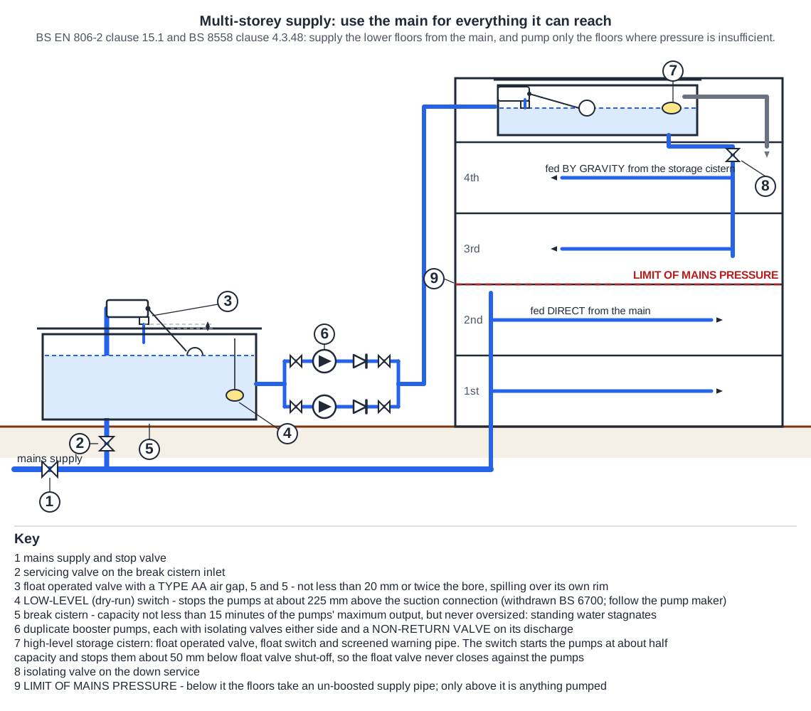
The main fills a low-level cistern through a float valve with a type AB air gap, and the duplicate booster pumps draw from that cistern and lift the water to the storage cistern at the top of the building. The cistern breaking the main is what names the system. There is no pressure vessel on the drawing, so it is not an “accumulator” arrangement.
On a cistern of 1,000 to 5,000 litres BS EN 806-2 (19.1.11) requires the lowest overflow pipe to be a warning pipe, but gives no dimension between it and the other overflow; the 25 mm between the two inverts is the arrangement drawn in the WRAS Water Regulations Guide (Figure 7.1), and is the figure to give. Do not confuse it with the closing level of the float valve, which BS EN 806-2 (19.1.8) puts at least 25 mm below the warning pipe, or 50 mm below the lowest overflow where there is no warning pipe.
A servicing valve sits immediately upstream of every float-operated valve so the valve can be worked on without draining the cistern — BS EN 806-2 clause 19.1.8 requires one, and Schedule 2 paragraph 16(2) of the Water Regulations puts one on the inlet of every storage, WC or urinal flushing cistern. The spherical plug type is chosen because a quarter-turn ball passes almost the full bore, where a screwdown pattern throttles the flow through a seat and a washer and can starve the float valve. BS 8558 clause 4.3.15 makes the same point from the other side, asking for servicing valves near outlets needing maintenance and "of a design that limits casual operation", and notes that spherical ball valves are well suited. The withdrawn BS 6700 said the same about screwdown resistance.
BS EN 806-2 19.1.6 requires a plastic cistern to be supported on a flat rigid platform fully supporting the bottom of the cistern over the whole of its area, and BS 8558:2015 4.3.41.2, the UK complement, adds that the platform should be extended beyond the outside edges of the cistern by not less than 150 mm on all sides, and where appropriate further still, so that the valves and the access cover can be reached safely. For a 1,000 mm x 800 mm base that is 150 mm added at each end and each side, so the smallest board is 1,300 mm x 1,100 mm. A board cut to the bare footprint supports the base but gives none of the margin the standard asks for, and anything smaller leaves part of the base unsupported so the cistern distorts.
Interlinked cisterns are made the same size and piped so the water crosses all of them: the guidance (G16.15) has the inlets and outlets located so that water passes through the whole of the cisterns and short-circuiting does not occur, and BS 8558 4.3.12.1 wants compartments of identical volume and shape with the piping arranged to give equal flow. Setting the float valves to the same level so that both cisterns fill and empty together is the practical way of achieving that equal turnover; no standard states it in those words, but letting one valve open before the other leaves water standing in the second cistern, and stagnation is exactly what the arrangement exists to prevent.
BS EN 806-2 clause 19.1.2 takes potable water directly off the main wherever practicable and, where that is not possible, from a cistern protected in accordance with 19.1.3. So all of the building, drinking points included, may be fed from one properly protected cistern. Drinking water needs neither its own separate cistern nor a pump at every point.
Linked cisterns are connected with the float valve feeding one cistern and the distributing pipe leaving the other, so that water circulates through both and neither stagnates. That is how Schedule 2 paragraph 16(5) of the Water Regulations is met, and BS EN 806-2 (19.1.4) says the same, inlets and outlets located to prevent short-circuiting within the cisterns, as did the withdrawn BS 6700. The near the bottom and at the middle positions are the traditional layout for achieving that; no standard fixes the exact positions.
A break cistern holds enough for the pumps to work on: BS 8558 (Annex A.2) puts its effective capacity at not less than 15 minutes of pump output, decided with the total storage requirement and its location in mind, and warns that it ought not to be oversized because the water would stagnate. So the aim in sizing it is a rapid turnover of the stored water. A 12 hour or a week's reserve would be a water quality problem, not a safeguard.
Going further: the lessons behind this article
This article is the public answer. Unit 331 of the Level 3 course takes the same ground to the depth the exam and the synoptic assignment ask for, in 3 lessons:
- Multi-storey supply: the mains limit and the break cistern
- Large cisterns: warning pipes, overflows and inlet valves
- Linked and sectional cisterns in the plant room
- Cold water systems: the Unit 331 guide — every article on this unit in one place
- All PlumbMate articles — Level 1, 2 and 3
- The Level 3 course — the whole 8202-35 Diploma