The best backflow protection on a job is usually the layout, not the device. The same is true of waste, of undue consumption and of contamination by stagnation: a system designed properly satisfies most of the Regulations by its shape, and only needs devices where the shape cannot do the work. That is what this module is about.
This article covers Module 5 of the PlumbMate Water Regulations course: how a system is fed and how flow rates are established, where stopvalves, servicing valves and drain taps have to go, and the dead leg problem — which is where the design questions and the contamination questions turn out to be the same question. There is a 10-question mock test at the end.
Designing the distribution
The course lists seven design factors, and they reduce to one sentence: what flow does the installation require, and what can the supply actually deliver? Every other decision follows from the gap between those two numbers.
Four ways of feeding an installation
- From a distributing pipe — fed from a storage cistern. The indirect system.
- Direct from a supply pipe — everything at mains pressure. The direct system.
- A combination of the two — typically the kitchen sink on the main for drinking, everything else from storage.
- Pumped.
The combined arrangement is worth understanding rather than memorising. The drinking water outlet goes on the main because that water is freshest and at fluid category 1; the rest goes on storage because storage buffers the demand and reduces what the main has to deliver at peak. Two different objectives, satisfied by putting different outlets on different sources.
Design flow rate and minimum flow rate
Two terms that get used loosely and mean different things:
- The design flow rate is what an outlet needs with a single outlet discharging.
- The minimum flow rate is what it must still achieve under simultaneous discharge, when several outlets are open at once.
The tabulated design rates worth carrying:
- WC cistern — 0.13 l/s
- Washbasin tap — 0.15 l/s
- Shower head — 0.2 l/s
- Bath tap G¾ — 0.3 l/s
- Bath tap G1 — 0.6 l/s
One adjustment that saves oversizing: mixer fittings may need only about 70 per cent of the tabulated rate, because the demand is shared between the hot and cold sides rather than drawn entirely from one.
The temperature the design has to hold
Cold water reaching any tap must not have been warmed above 25 °C, and the design target is below 20 °C. This is a design constraint, not just an insulation detail. Route matters: a cold main run through an airing cupboard, alongside a flow and return, or above a ceiling in a heated commercial building will breach it regardless of how well it is lagged. The decision that fixes it is made on the drawing, not with a roll of insulation afterwards.
Stopvalves
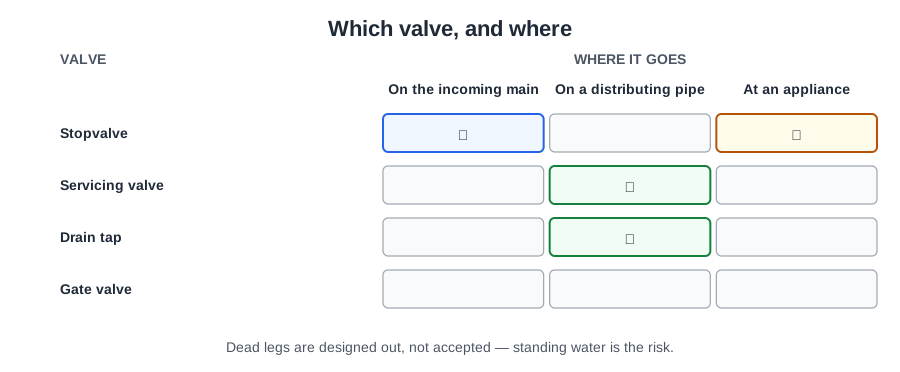
A stopvalve is defined as a valve, other than a servicing valve, used to shut off the flow of water in a pipe. On a drawing it is shown with a dot in the centre of the valve symbol, which is what distinguishes it from a servicing valve.
Where they go
The external stopvalve sits at the boundary and is normally provided and maintained by the water undertaker. It is not yours, and it is not the one the customer should be using in an emergency.
The internal stopvalve goes inside the premises, above floor level, near where the supply pipe enters. Its defining requirement is functional rather than positional: it must be positioned so that closing it prevents supply to all points of use. If closing the stopvalve leaves an outlet still live, it is in the wrong place, however tidily it is fitted.
Two multi-occupancy rules follow from the same principle:
- Separate premises must be capable of being shut off without affecting any other premises. One flat's isolation must not turn off the neighbours.
- On a common supply, there must be a stopvalve each occupier has access to. Whether it is inside or outside is immaterial — access is the test.
Type, visibility and labelling
Spherical valves are acceptable above and below ground, but where one is used as a stopvalve it needs an integral handle or lever — something that can be operated by hand, without a tool, by someone who has water coming through a ceiling.
Covers must be visible at all times and must not be concealed under carpet, tiling or wallpaper. This gets breached constantly during refurbishment work, usually by a flooring contractor who did not know what the small metal plate was. It is worth pointing out before the carpet goes down rather than afterwards.
Stopvalves should be labelled so that the part of the system they control can be identified. On a domestic property that may seem fussy. In a plant room with nine valves on a manifold it is the difference between isolating a leak in thirty seconds and isolating the wrong thing twice first.
Servicing valves and drain taps
The general requirement: systems must be capable of being drained down, with enough servicing valves and drain taps to minimise the discharge of water when work is done. The purpose is waste, straight from Regulation 3 — if changing a float valve means dumping a 230 litre cistern, the design is causing waste.
Where servicing valves are required
- On the inlet to every storage cistern, combined feed and expansion cistern, WC flushing cistern and urinal flushing cistern, and it must be adjacent to the cistern.
- On the outlet of every storage cistern — except one feeding a primary circuit.
- Fitted as close as reasonably practical to the float-operated valve or inlet device.
The primary circuit exception is a safety rule wearing a plumbing rule's clothes. A feed and expansion cistern's outlet is the route by which the primary circuit is fed and, more importantly, the route by which it expands and vents. Put a valve on it and somebody will eventually close it, leaving a heat source connected to a circuit that cannot expand. The exception exists so that valve is never there to be closed.
Servicing valves may be screwdown or spherical, and levers are permitted. Unlike stopvalves, there is no requirement for a hand-operable handle — a servicing valve is for a plumber doing planned work, not a householder in a panic.
Drain taps
- Screwdown pattern to BS 2879, or an approved spherical type — but only in a frost free location.
- They must be accessible, and must not be buried or submerged.
The frost restriction on spherical drain taps has a specific mechanism behind it, and it is worth knowing because it also tells you how to leave a drained system. A spherical valve traps water inside the ball when it is closed, and that trapped water has nowhere to go when it freezes, so the valve body splits. Which gives the practical instruction: after draining down, leave spherical valves half open. A ball at half turn has its bore aligned with nothing sealed, so the trapped volume can escape.
And operational fittings must be readily accessible and labelled — the same principle as stopvalves, for the same reason.
Dead legs
This is where design and contamination meet, and the requirements are stricter than most people expect.
A capped branch is still a dead leg
When a draw-off fitting is permanently removed, its branch must be disconnected at its source. Capping it is not compliance.
The reasoning is worth spelling out because the capped-end habit is so ingrained. A capped branch still contains water. That water never moves, because there is no outlet to draw it. It sits at room temperature, warms above 20 °C for part of the year, and becomes a bacterial reservoir connected to the wholesome system. Every time flow passes the tee, some of that water joins it.
Note also that there is no provision allowing a disconnected fitting to be left for a set number of days. People frequently believe there is a grace period — a fortnight, a month — and there is not. Remove the fitting, disconnect the branch at source.
The same logic runs forwards: pipework installed for future use must not be connected until the terminal fittings are ready. First fix pipework capped off and left live for eight months is the same reservoir, created deliberately.
And a system that is not in regular use and not regularly flushed triggers disinfection — the Module 4 requirement, which is really this problem viewed from the other end.
Hot water dead legs, and undue consumption
The hot side has its own version. Drawing off litres of cold water before a tap runs hot is undue consumption — an offence under Regulation 3.
That is a stronger statement than the trade usually treats it as. A long uninsulated run from cylinder to en-suite is not merely inconvenient; the water wasted every time somebody waits for it is a contravention.
Five remedies, roughly in order of how well they work:
- Site the cylinder close to the outlets it serves — the only one that solves the problem rather than managing it.
- A secondary hot water return.
- Trace heating.
- Point-of-use water heaters for outlets a long way from everything.
- Insulation, which slows the cooling but does not shorten the pipe.
Where none of that is possible, there are maximum lengths for uninsulated hot pipe:
- 12 mm — 20 m
- 22 mm — 12 m
- 28 mm — 8 m
- over 28 mm — 3 m
The lengths fall as the diameter rises, and that is the whole logic of the table: what is being limited is the volume of cooled water that has to be run off, not the distance. A 28 mm pipe holds roughly five times the water of a 12 mm one per metre, so it earns far fewer metres.
Putting the module together
Design so the layout does the work: the right source for each outlet, flow rates established properly, cold routes that stay below 25 °C. Then valves in the positions that make the system controllable — a stopvalve that isolates everything, servicing valves that let one cistern be worked on without draining a house, drain taps that are accessible and will survive a winter. Then no dead legs, on either side, because a branch with no flow is a contamination problem however neatly it is capped.
📝 10-Question Mock Test
Click an option to see whether you got it right. Explanations appear instantly — no submitting at the end.
One outlet against several at once. Mixer fittings are an adjustment worth knowing on top of this: they may need only about 70 per cent of the tabulated rate, because demand is shared between the hot and cold sides.
Two different objectives satisfied by putting different outlets on different sources. It is worth understanding rather than memorising, because it explains the whole shape of the arrangement.
Functional rather than positional. It goes inside the premises, above floor level, near where the supply enters — but if closing it leaves an outlet still live, it is in the wrong place however tidily it is fitted.
Visible at all times. This gets breached constantly during refurbishment, usually by someone who did not know what the small metal plate was — which is why it is worth raising before the flooring goes down.
A safety rule wearing a plumbing rule's clothes. A feed and expansion cistern's outlet is how the primary circuit expands and vents; a valve there is a valve somebody will eventually close, leaving a heat source on a circuit that cannot expand.
Adjacent, and as close as reasonably practical to the float valve. The purpose is minimising discharge when the valve is worked on — a servicing valve ten metres back does not achieve that.
And it gives you the practical instruction for draining down: leave spherical valves half open, so the trapped volume can escape. The alternative is a screwdown pattern to BS 2879, which has no such restriction.
A capped branch still holds water that never moves, warms above 20 °C for part of the year, and becomes a bacterial reservoir connected to the wholesome system. There is no provision allowing a disconnected fitting to be left for a set number of days.
Undue consumption is one of the five things Regulation 3 prohibits, and this is exactly it. The remedies run from siting the cylinder close — the only one that solves rather than manages the problem — through secondary return, trace heating and point-of-use heaters.
Volume, not distance. A 28 mm pipe holds roughly five times the water of a 12 mm one per metre, so it earns far fewer metres before the run-off becomes undue consumption.
Almost everything in this module is Regulation 3 in a different costume. Servicing valves are about waste. Dead legs are about contamination. Hot water run-off is about undue consumption. Design the layout so those three cannot happen and the compliance follows.
The one to carry away: a capped branch is still a dead leg. When a fitting is permanently removed, the branch is disconnected at its source — and there is no grace period allowing it to be left capped for a few days first.