Hot water is the only part of a plumbing system that can kill somebody in two entirely different ways. Too cold and it grows legionella. Too hot and it scalds. The temperatures that deal with each pull in opposite directions, and almost everything in this module is the resolution of that conflict: keep it hot where it is stored and moved, cool it at the last possible moment before it reaches a person.
This article covers Module 11 of the PlumbMate Water Regulations course: the unvented safety stack and what each layer does, the temperature regime and where each figure comes from, vent pipe requirements, discharge pipework D1 and D2, and hot water dead legs. There is a 10-question mock test at the end.
Unvented hot water: the safety stack
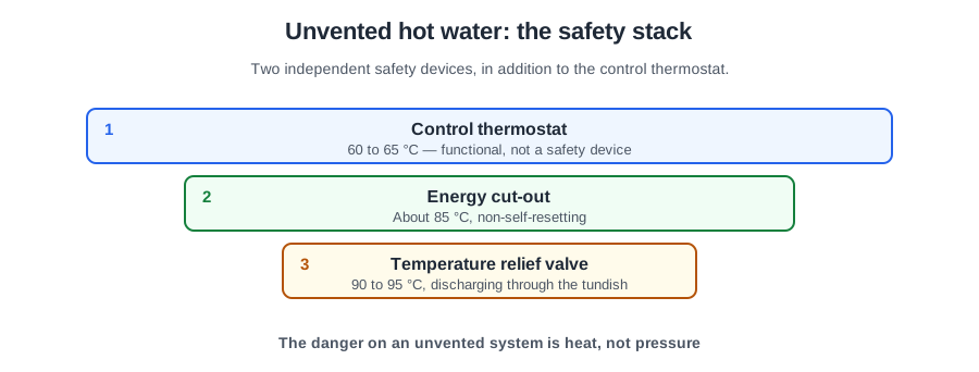
An unvented hot water storage vessel is one with no vent pipe to the atmosphere. That single fact is what makes everything else necessary. A vented cylinder has an open route to atmosphere, so it cannot pressurise and it cannot exceed 100 °C. Take that route away and both become possible.
The 15 litre threshold
Instantaneous heaters of 15 litres or less are exempt. Storage vessels above 15 litres need the full stack. Below the threshold there is simply not enough stored energy for the failure to be dangerous.
The four layers
- A temperature control device — the thermostat. The first line, and the only one that operates in normal use.
- A temperature relief valve, or a combined temperature and pressure valve.
- An expansion valve.
- An expansion vessel, or an integral expansion system.
The layering is the point. Each device assumes the one before it has failed, and no single failure reaches the customer.
Expansion is handled twice
Worth stating clearly because people conflate the two components. The expansion vessel takes up expansion in normal operation. The expansion valve is the backup for when the vessel fails.
A vessel that has lost its charge is a common and quiet failure — nothing looks wrong, and the first symptom is the expansion valve weeping every time the cylinder reheats. That is the system working as designed: the backup has taken over and is telling you.
The expansion valve goes on the supply pipe close to the vessel, with no intervening valves, and discharges at not less than 0.5 bar (50 kPa) above normal operating pressure.
The temperature relief valve
The TRV is located directly on the vessel — not on a pipe leading from it — with sufficient capacity to keep the stored water below 100 °C. Its discharge pressure is 0.5 bar above the greater of the maximum working pressure or the expansion valve's operating pressure, so it never opens before the expansion valve has had its chance.
Two general requirements on all relief valves: they must close automatically after discharge and be watertight when closed. A valve that discharges once and then dribbles for the rest of its life has failed, even though it did its job at the moment that mattered.
And where a fusible plug is fitted, the relief valve must operate not less than 5 °C below it. The reason is sequencing: the resettable device acts first. A fusible plug is a one-shot component that dumps the cylinder and needs an engineer; a relief valve closes again. You want the recoverable failure to happen first.
Vented vessels are not exempt from thought
Vented vessels with an immersion heater need either a dedicated cistern or a non-self-setting thermal energy cut-out. An immersion heater with a failed thermostat will happily boil a vented cylinder, and “non-self-setting” matters: a cut-out that resets itself lets the fault repeat unseen.
And the absolute: 100 °C is the ceiling at any point in a hot water storage system, irrespective of fuel. Gas, electric, oil, solid fuel, heat pump — the number does not change.
The temperature regime
Here is the conflict, resolved:
- 60 °C minimum storage.
- 50 °C at the terminal fitting within one minute of fully opening the tap (55 °C in healthcare).
- 50 °C or more back at the cylinder on a secondary return (55 °C in healthcare).
- 43 °C maximum discharge at public outlets, achieved with a thermostatic mixing valve.
The way to hold this in your head: the upstream figures are minimums, set for bacteria. The outlet figure is a maximum, set for scalding. They are not a range with a target in the middle. Water is kept deliberately too hot to be safe to touch right up until the last fitting, and only then blended down.
The 50 °C-in-a-minute figure is a performance test, not a setting. It is how you demonstrate the distribution is doing its job, and it is the test that fails on a long uninsulated run to a distant en-suite.
You will see older figures too. The 1999 Water Regulations guidance (G18.2 and G18.4) asks for distribution at 55 °C and 50 °C within 30 seconds where practicable. BS 8558 (2015) and HSE’s HSG274 use 50 °C within a minute, which is what you work to.
Mixing valves
Typical set points: 41 °C basin and shower, 38 °C bidet, 44 °C bath unassisted.
Two installation principles:
- Fit TMVs one per outlet, and keep the mixed run as short as possible. Blended water sits in the bacterial growth range, so every metre of pipe downstream of a TMV is pipe holding water at the worst possible temperature. A TMV three metres from the tap creates the problem it was fitted to avoid.
- Group mixing is possible but not recommended for high risk applications, for the same reason at a larger scale.
Two figures that get confused with the law
These come up constantly and are worth separating:
- 48 °C is the Approved Document G3 ceiling at a bath in a new dwelling (or one formed by a change of use; in any other home it is good practice). That is Building Regulations, a different instrument from the Water Regulations. Both apply; they are not the same document and they are enforced by different people.
- 41–43 °C is the TMV2 factory setting, not a legal limit. The distinction matters: a setting is commissioned; a ceiling must not be exceeded. Quoting a factory setting as though it were a legal maximum leads to arguments that cannot be resolved because both sides are talking about different kinds of number.
Two more:
- Cold water: 25 °C ceiling at any tap, 20 °C practical target. The cold side has its own bacterial limit.
- Healthcare premises follow the HSE guidance on safe hot water and surface temperatures, which goes further than the general position.
And an honest caveat the course makes: the 60 and 50 °C figures may not be achievable with instantaneous or combination boilers, which have no store to hold a temperature and no secondary circulation. That is a real limitation of the appliance type, not a failure of the installation.
Vent pipes
- Vent pipes from primary and secondary systems: not less than 19 mm internal diameter.
- Secondary vents must be insulated against freezing. A frozen vent leaves what is nominally a vented system with no safety route at all — a sealed system with none of a sealed system's protection.
- No primary vent over a cistern holding wholesome water, and no secondary vent over a feed and expansion cistern. Each vent discharges over its own cistern, keeping primary and wholesome water apart.
Vent height above the overflow, for gravity circulation:
V = 0.04H + 0.15 (metres)
— where H is the height of the system. Where a pump is fitted, allow for the induced head on top of that figure. A pump can push water up a vent that was correctly sized for gravity, and the result is water discharging into the cistern every time the pump runs.
Discharge pipework: D1 and D2
Paragraph 19 sets the principle: discharges must be made in a safe and conspicuous manner. Safe, so nobody is scalded. Conspicuous, so a discharge is noticed rather than quietly soaking into the ground for two years.
D1 — valve to tundish
- no more than 600 mm of pipe between the valve outlet and the tundish (Approved Document G 3.54);
- tundish vertical, in the same space as the cylinder, as close as possible to the valve;
- not less than the valve outlet size;
- metal, such as copper (Approved Document G 3.50).
D2 — tundish to termination
- A 300 mm vertical drop below the tundish before any bend, then a continuous fall of at least 1 in 200 (Approved Document G, 3.56).
- One size larger than the valve outlet, plus one further diameter for each additional 9 m of equivalent resistance — and bends count towards that resistance.
- Insulated outside the thermal envelope, and it must terminate safely, with no risk to persons.
The resistance rule is the one that gets skipped. A run with six bends in it has considerably more equivalent length than its measured length, and a D2 that is one size too small will not pass the full discharge — which means the tundish overflows into the room.
The expansion valve may discharge into the same tundish, or have its own arrangement not less than its outlet size.
Hot water dead legs
The same problem as Module 5, from the hot side. Pipes carrying hot water to a tap, longer than the tabulated length, must be insulated to BS 5422:
- 12 mm — 20 m
- up to 22 mm — 12 m
- up to 28 mm — 8 m
- over 28 mm — 3 m
The table is by outside diameter, and the limit falls as diameter rises, because wider pipe holds more standing water per metre. It is a volume limit expressed as a length.
Separately: all fittings forming part of a primary or secondary hot water circulation system must be insulated, whatever their length. A circulating system is holding water at temperature continuously, so there is no short run that escapes.
Five ways to cut dead legs, and one of them is better than the rest: insulation, trace heating, a hot water return, point-of-use heaters, and siting the cylinder close to the outlets. Siting the vessel close is the cheapest and most effective — and it is a design decision, made once, on a drawing, at no cost. Every other item on that list is money spent managing a problem that did not have to exist.
One trap worth flagging: a secondary return coming back below 50 °C (55 °C in healthcare) pumps water around the building towards the bacterial growth range, continuously, past every outlet. An underperforming secondary return is worse than none.
Putting the module together
Layered protection on unvented storage, each layer assuming the last has failed. A temperature regime with minimums upstream for bacteria and a maximum at the outlet for scalding, blended as late as possible. Vents sized and insulated so the safety route stays open. Discharge pipework sized for its actual resistance and terminating where somebody will see it. And short hot runs, because the cheapest fix is deciding where the cylinder goes.
📝 10-Question Mock Test
Click an option to see whether you got it right. Explanations appear instantly — no submitting at the end.
Below 15 litres there is not enough stored energy for the failure to be dangerous. The stack is a temperature control device, a temperature relief or combined T&P valve, an expansion valve, and an expansion vessel or integral expansion system.
Expansion is handled twice: the vessel takes it up in normal operation, the valve is the backup for when the vessel fails. A vessel that has lost its charge is a quiet failure, and this is the system telling you about it.
Sequencing. A fusible plug is a one-shot component that dumps the cylinder and needs an engineer; a relief valve closes again. You want the recoverable failure to happen first.
Not a range with a target in the middle. Water is kept deliberately too hot to touch right up to the last fitting, then blended. The 50 °C at the outlet within one minute is a performance test of the distribution, not a setting.
Confusing a factory setting with a legal limit leads to arguments that cannot be resolved, because the two sides are talking about different kinds of number. 48 °C at a bath in a dwelling is the G3 ceiling — Building Regulations, a different instrument from the Water Regulations.
A TMV three metres from the tap creates the problem it was fitted to avoid. Group mixing is possible but not recommended for high risk applications, for the same reason at a larger scale.
Vents from primary and secondary systems must be not less than 19 mm internal diameter. No primary vent over a cistern holding wholesome water, and no secondary vent over a feed and expansion cistern.
A pump can push water up a vent that was correctly sized for gravity, and the result is water discharging into the cistern every time the pump runs.
The rule that gets skipped. A D2 one size too small will not pass the full discharge, which means the tundish overflows into the room. D2 starts one size larger than the valve outlet, with a 300 mm vertical drop below the tundish before any bend.
Every other item on the list is money spent managing a problem that did not have to exist. Note too that a secondary return coming back below 50 °C pumps water around the building towards the bacterial growth range — an underperforming return is worse than none.
The temperature figures only make sense once you see them as two opposing requirements rather than one range. Hot enough to kill bacteria everywhere the water is stored or moved; cool enough not to scald only at the point it meets a person.
The one to carry away: fit TMVs one per outlet and keep the mixed run short. Blended water sits in the growth range, so a TMV three metres back down the pipe creates the problem it was fitted to prevent.