A boiler you have just replaced fires every few minutes all afternoon while nobody is in and nothing is calling for heat. The appliance is fine. What is missing is in the wiring.
The short answer
Boiler interlock is not a device you can buy. It is the interconnection of the system controls — thermostats, programmers and motorised valves — wired so that the boiler and pump are switched off when there is no demand for space heating or hot water.
That is the first line of the compliance guide's table of minimum controls, and the first thing a new wet system has to satisfy. It also explains the whole architecture of the standard plans: the boiler is fired by a valve's auxiliary switch, not directly by a clock.
And one trap is stated plainly in the guidance: TRVs alone are not sufficient for boiler interlock, because a TRV cannot switch the boiler off.
Time controls and temperature controls
A customer says the hot water comes on with the heating and cannot be had on its own. You open the airing cupboard and find a time switch where a programmer should be. The two look almost identical on the wall, and the difference is the whole complaint.
- A time switch is a clock with one set of contacts. Heating and hot water go together.
- A programmer is a clock with two or more sets of contacts that can be operated independently, so heating and hot water have their own on and off times. That independence is what the regulations mean by separate time control, so on any system with a stored hot water cylinder the programmer is the minimum.
- A programmable room thermostat holds a schedule and senses room temperature — a time control and a temperature control at once.
On the temperature side:
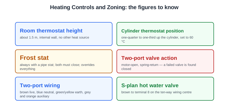
- The room thermostat senses air temperature in one room. Where it goes matters as much as what it is: about 1.5 m above floor level, on an internal wall, out of direct sunlight, away from draughts and away from any other heat source. That room becomes the reference room for the circuit, and NA.4.6.1 says TRVs should not be fitted in the same room as the room thermostat. Two controls governing one room fight each other and the system hunts — and that circuit is the one you want left open so the pump always has somewhere to push water.
- A TRV senses the air around it and throttles the water into its own radiator. The National Annex is clear that TRVs must not be the sole means of control: they cannot shut the boiler off.
- The cylinder thermostat straps on and senses the stored water. Fit it one-quarter to one-third of the way up the cylinder, where it reads the bulk of the stored water rather than the hot layer at the top, and set it to 60 °C.
- The frost thermostat protects an exposed boiler and is always fitted with a pipe thermostat: the frost stat reads air, the pipe stat reads water, and both must close before the boiler fires. A frost stat overrides all the other controls, so the system runs to protect itself even when the programmer says off.
All of these meet at the wiring centre. It is not a control — it is the common terminal block where permanent live, neutral and earth, the programmer, the thermostats, the valves, the boiler and the pump are brought together, so the interconnections can be made and checked in one accessible place. Anything you do inside it is live working unless you make it dead first: isolate, lock off, and prove dead with an approved voltage indicator, proved on a known supply or proving unit before and after.
Zone valves
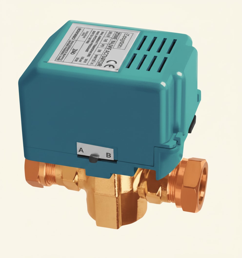
You are handed a photograph of a valve head with five wires: grey, white, orange, blue and green-and-yellow. Before you look at anything else you already know two things. It is a three-port mid-position valve, and the system is a Y-plan.
A two-port motorised zone valve opens or closes one circuit. It is motor-open and spring-return: a synchronous motor drives it open against a spring, and when the thermostat drops the power a return spring closes it. There is no motor drive in the closing direction, which is why a failed valve is usually found closed.
Inside the head is an auxiliary switch. It makes only when the valve has actually reached the open position, and it sends a switched live onward to the boiler and pump. That is the mechanical heart of boiler interlock: the boiler cannot fire until a valve is genuinely open and there is somewhere for the heat to go.
The wires are brown motor live, blue neutral, green and yellow earth, and grey and orange for the auxiliary switch, the orange being the switched live out. On the standard ten-way wiring centre used in the S-plan diagrams, the brown wire of the hot water valve lands on terminal 8. Valve size follows the boiler: 22 mm up to around 20 kW, 28 mm or larger above that.
The two three-port valves
Both have the same port markings, and this is a very common exam question:
AB is the common inlet, the flow from the boiler. A serves the heating. B serves the hot water cylinder.
- A mid-position valve can sit in three positions: A only, B only, or a mid-position sharing the flow between both circuits at once. Five wires: grey from the cylinder thermostat, white from the room thermostat, and orange, the switched live from its own auxiliary switch that feeds the boiler and the pump.
- A diverter valve looks similar but cannot share. It sends the flow to hot water or heating, never both, so it is used where the design calls for hot water priority. It is identifiable at a glance because it has only three wires: live, neutral and earth.
NA.4.6.4 puts the choice like this: a two-port valve opens or closes a single circuit supplying one zone, a three-port valve controls two zones only, and a mid-position valve is recommended where shared flow is wanted, with a diverter used where the design is intended for a priority arrangement.
The automatic bypass
When every zone valve and every TRV has closed, the pump has nowhere to push water. Dead-heading a pump is not a long-term plan, and a boiler that has just shut down still holds heat in its casing which has to be carried away or it trips its high-limit thermostat.
The answer is an automatic bypass valve: a spring-loaded differential pressure valve connecting the flow immediately after the pump to the return. It is opened by the pressure created within the system — not by a thermostat or a signal. As the paths close, the pressure across it rises until the spring gives way.
Where the boiler manufacturer's instructions advise a bypass, an automatic bypass valve is provided and the minimum pipe length instructions followed. A fixed, wedged-open lockshield is not acceptable, because it bleeds flow away all the time. A mid-position system always has a path open through at least one circuit, which is why a Y-plan may be found without one; a boiler with a pump overrun circuit always needs one.
S-plan and S-plan plus
Two motorised valve heads side by side, one on a pipe to the cylinder and one heading off to the radiators. Two two-port valves means S-plan, and from that single observation you can predict the whole of the wiring.
Each valve has its own thermostat. The cylinder thermostat opens and closes the hot water valve directly; the room thermostat does the same for the heating valve. Each valve, on reaching the open position, makes its own auxiliary switch and sends a switched live into the wiring centre. Both switched lives are joined there, so either circuit calling will fire the boiler and run the pump, and when neither is calling both are switched off.
That is the interlock. There is no path from the programmer straight to the boiler: the boiler is fired by the valves, and the valves are opened by the thermostats. The programmer decides only when each circuit is allowed to ask.
An S-plan plus is the same system with a third two-port valve, splitting the heating into two space heating zones, most often upstairs and downstairs, each with its own room thermostat and time control. That is why a new dwelling of 150 m² or more on an S-plan needs a minimum of three zones: two space heating zones plus the hot water.
An S-plan can be open vented or sealed. Two two-port valves plus a feed and expansion cistern with a cold feed and open safety vent is an open vented S-plan; the same valves with a filling loop, pressure gauge and expansion vessel make it a sealed one.
Why S-plan plus at low temperatures
On a heat pump, S-plan plus is preferred over a mid-position arrangement, because a mid-position valve can pass water to both circuits at once, so it cannot enforce hot water priority. A boiler can serve heating and hot water together because it has spare capacity and one flow temperature suits both; a heat pump produces a single flow temperature and is sized to the heat loss, so it has to serve one or the other. Two-port valves that genuinely close are what make that possible.
The consequence has to be explained at handover. Under hot water priority the heating zones close and the flow temperature rises while the cylinder reheats, then drops back to the heating curve and the zones reopen. The radiators really are off for the hour or two the reheat takes. Schedule it away from the coldest hours and the morning warm-up, and tell the customer — or the first person to notice will report a fault.
Y-plan and W-plan
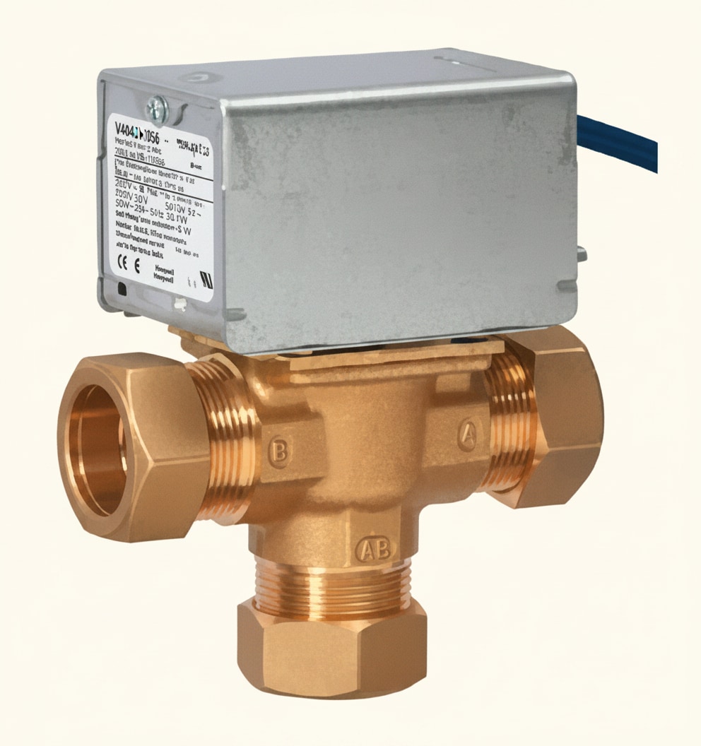
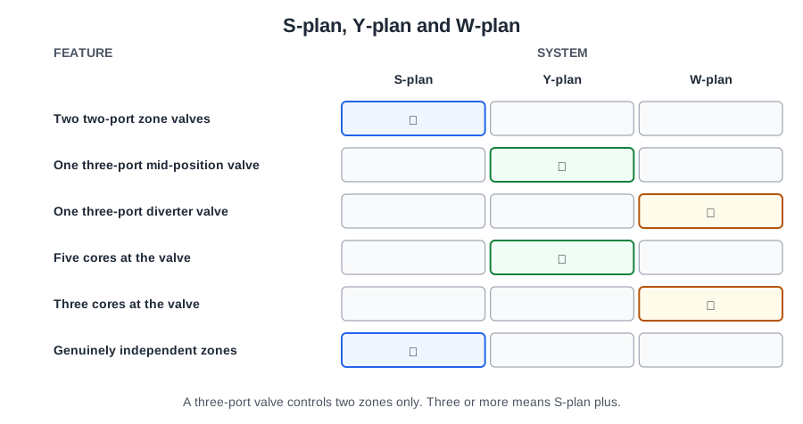
Two wiring diagrams look almost the same: one motorised valve, a cylinder thermostat, a room thermostat, a boiler and a pump. Count the wires on the valve.
Y-plan is built round a single three-port mid-position valve, so it can supply heating, hot water, or both at the same time. The valve has five wires, and the orange is the output of its own auxiliary switch — the switched live that feeds the boiler and pump. So on a Y-plan the boiler and pump are switched directly by the three-port valve, not by either thermostat. Both thermostats talk to the valve; the valve talks to the boiler.
W-plan uses a three-port diverter valve. Same port markings, but no mid position. It sends the flow to hot water or heating, never both, and the cylinder wins: the stored water must be satisfied before the heating operates. It is identifiable because there are only three wires from the valve — there is no auxiliary switch output to trace.
NA.4.6.3.1.2 gives the rule in one sentence: shared flow, use a mid-position valve; priority, use a diverter.
The practical difference shows up in the customer's experience. On a Y-plan, a call for hot water on a cold evening does not stop the radiators. On a W-plan it does, until the cylinder is up to temperature. And on a low temperature system that priority is not a nuisance but a requirement — which is why priority there is built from two-port valves that genuinely close, rather than from a diverter that may be decades old.
How many zones
You are quoting for a four-bedroom house and the floor area comes to 168 m². That number changes the job.
The Approved Document L rule (Volume 1, 2021, paragraph 5.14, which replaced the Domestic Building Services Compliance Guide in June 2022) is short: new dwellings with a floor area of 150 m² or more should have at least two space heating zones, each with its own independently controlled heating circuit. Under 150 m² a single zone is permitted, although two is usually the better design and the SAP notional dwelling assumes two.
Two details matter. The relevant floor area is the area within the insulated envelope, including internal cupboards and stairwells — not the carpeted area. And a heating circuit means a pipework run controlled by its own zone valve. Two thermostats on one valve is not two zones.
The zones are usually upstairs and downstairs; in a single-storey dwelling, the living area against the rest. The one exception is a single-storey open-plan dwelling where the living area is more than 70 per cent of the total floor area, where sub-zoning the temperature is not appropriate and a programmer and room thermostat are accepted instead.
What each zone has to have
Each space heating circuit needs independent time control, plus either a room thermostat or programmable room thermostat in a reference room served by that circuit together with TRVs on all radiators outside the reference rooms, or individual networked radiator controls in every room.
The reference room is the room that acts as the main temperature control for the circuit, and it is the room where no other form of system temperature control is present — which is the rule behind the familiar instruction that the reference room's radiator carries no TRV.
Hot water has its own requirement whatever the floor area. Where the hot water comes from a store rather than instantaneously, the circuit needs independent time control and electric temperature control — a cylinder thermostat with a zone valve or a three-port valve. Where a zone valve is not appropriate, as with some thermal stores, a second pump may be substituted.
So: separate time and temperature control of heating and hot water applies to a dwelling of any floor area. Two space heating zones is the extra requirement that arrives once a new dwelling reaches 150 m².
A heating design normally works to a minimum design temperature of 21 °C in every room except the bedrooms, and a zoned system is what lets those different design temperatures actually be delivered rather than every room following one thermostat in the hall.
One warning for low temperature systems. Aggressive zoning fights a heat pump: close two zones out of three on a mild day and the flow through the appliance can fall below its minimum, so it short cycles. Leaving one circuit permanently open is often the neatest answer.
CHeSS, and signing the work off
The Central Heating System Specification, CHeSS CE51 2008, sets out the recognised packages of controls:
- Good practice HR7 (regular boiler with a separate store): full programmer, room thermostat, cylinder thermostat, boiler interlock, TRVs on all radiators except in rooms with a room thermostat, and an automatic bypass where needed.
- Good practice HC7 (combination boiler): time switch, room thermostat, boiler interlock, TRVs except in the room thermostat's room, automatic bypass.
- Best practice HR8 and HC8 replace the programmer and room thermostat with a programmable room thermostat and invite more advanced controls such as weather compensation.
Note what stays in every list: boiler interlock is in all four. On a regular boiler it is achieved by correctly interconnecting the thermostats and motorised valves through the wiring centre; on a combination boiler it is achieved by fitting a room thermostat.
Note also where the guidance sits. Approved Document L Volume 1 is the Building Regulations guidance for dwellings and points to the compliance guide for the detail. Since the 2021 edition it covers new and existing dwellings and has replaced L1A and L1B, which no longer exist. Volume 2 covers buildings other than dwellings.
Gas work is carried out under the Gas Safety (Installation and Use) Regulations 1998 by a business registered with the Gas Safe Register; oil by OFTEC; solid fuel by HETAS. Electrical work falls under Approved Document P: a fused spur to supply a boiler is minor work, so the customer should receive a minor works certificate. The building control body must be given a notice of completion of commissioning, and where the installer is registered with a competent person scheme the scheme provides that notification. The Benchmark checklist is completed and left with the customer, and the same booklet holds the service log.
Compensation, optimum start and smart controls
A customer with a new condensing boiler says the house is warm but the gas bill has not moved. The controls are a programmer and a single room thermostat, and the boiler runs at a fixed 75 °C from October to April. Everything works. Nothing is compensating.
Weather compensation maintains internal temperatures by varying the flow temperature from the heat generator relative to the measured outside air temperature. An outside sensor feeds a compensation curve: colder outside, higher flow temperature; milder, lower.
Two practical points. The sensor goes on a north or north-east facing wall so direct sunshine does not fool it. And the curve is set as low as the building will tolerate and then proven over a cold spell, because every extra degree of flow temperature costs efficiency.
This is where most of the saving on a condensing boiler or heat pump actually comes from: the design flow temperature is only needed on the coldest days, and the system spends the rest of the winter below it. A fixed flow temperature all winter throws that away. Load compensation does the same job from the other end, varying flow temperature according to the measured response of the heating system rather than the outside air.
Two controls are often confused because both move the start time:
- Delayed start. The user sets the normal on time; at that moment the control compares actual indoor temperature with the temperature wanted, and if the house is already close it delays firing the boiler.
- Optimum start. The user sets the occupancy time and the temperature wanted, and the controller works out the heat-up period and starts as late as it can while still reaching the setpoint on time, whatever the weather.
So a control that senses inside or outside temperature and moves the start time accordingly is optimum start. It is worth far more on a slow system than a fast one: where preheat can be two or three hours and varies with the weather, guessing the start time is expensive. Night setback works alongside it and reduces the risk of condensation.
Smart thermostats over Wi-Fi bring some of this to an ordinary house, and remote control is genuinely useful. But check the specification before fitting one on a low temperature system: many popular smart thermostats are sophisticated switches, and a switch is the least useful thing to put on a heat pump. Confirm the control can genuinely weather compensate, not merely schedule, and that the system still works when the internet does not.
🔢 The numbers worth memorising
- Room thermostat height
- about 1.5 m, internal wall, no other heat source
- Cylinder thermostat position
- one-quarter to one-third up the cylinder, set to 60 °C
- Frost stat
- always with a pipe stat; both must close; overrides everything
- Two-port valve action
- motor-open, spring-return — a failed valve is found closed
- Two-port wiring
- brown live, blue neutral, green/yellow earth, grey and orange auxiliary
- S-plan hot water valve
- brown to terminal 8 on the ten-way wiring centre
- Valve size
- 22 mm to about 20 kW, 28 mm or larger above
- Three-port ports
- AB boiler flow, A heating, B cylinder
- Mid-position valve
- five wires; diverter valve three
- Automatic bypass
- opened by system pressure, not by a signal
- Zoning threshold
- 150 m² or more in a new dwelling — at least two space heating zones
- Open-plan exception
- living area over 70 per cent of the total floor area
- Design room temperature
- 21 °C, bedrooms cooler
- Control packages
- CHeSS CE51 2008 — HR7, HC7, HR8, HC8
- Outside sensor
- north or north-east facing wall
⚠️ Where people go wrong
- Fitting a time switch where a programmer is required. With a stored cylinder, the programmer is the minimum.
- Fitting a TRV in the reference room. Two controls on one room make the system hunt.
- Relying on TRVs for interlock. A TRV cannot switch the boiler off.
- Setting a cylinder stat near the top. It then reads the hot layer, not the bulk — a quarter to a third up.
- Wiring a frost stat without a pipe stat.
- Calling the wiring centre a control. It is a terminal block.
- Wedging a lockshield open as a bypass. It bleeds flow away all the time.
- Counting two thermostats on one valve as two zones. A zone means its own zone valve.
- Measuring the carpeted area for the 150 m² rule. It is the area within the insulated envelope.
- Using a mid-position valve to give hot water priority. It can feed both at once.
- Zoning a heat pump aggressively. Below its minimum flow it short cycles.
- Fitting a smart thermostat to a heat pump and calling it compensation. Check it can compensate, not just schedule.
- Confusing delayed start with optimum start. Optimum start works back from the occupancy time.
📝 10-Question Self-Test
Straight from the Level 3 course question bank. Click an option to see whether you got it right — the explanation appears instantly, and there is nothing to submit.
A TRV throttles the flow to a radiator once its room is warm, so the boiler is not heating rooms that are already at temperature. Less heat used means lower running costs.
Room thermostats and sensors should be positioned around 1.5 m above floor level, out of sunlight, draughts and away from heat sources.
The auxiliary switch inside the three-port mid-position valve (the orange wire) is what feeds the boiler and pump.
The sensor goes a quarter to a third of the way up the cylinder, where it reads the bulk of the stored water rather than the hottest layer at the top. Fitted under the draw-off it would satisfy early and leave most of the cylinder cool; at the very bottom it would read the incoming cold and keep the heat on long after the cylinder was hot. The recommendation is in the National Annex to BS EN 12828.
Since the 2021 edition, Approved Document L Volume 1 covers the conservation of fuel and power in dwellings, new and existing, and points to the Domestic Building Services Compliance Guide for the heating system requirements. It replaced the separate L1A (new dwellings) and L1B (existing dwellings) documents, which no longer exist; Volume 2 is for buildings other than dwellings.
Approved Document L (Volume 1, 2021, paragraph 5.14) requires a new dwelling of 150 m2 or more to have at least two independently controlled heating circuits: two space heating zones, each with its own time and temperature control. It replaced the Domestic Building Services Compliance Guide in June 2022. Two zones sharing one room thermostat are one zone split into two pipes, and TRVs on a single zone do not make it two.
Optimum start reads the inside, and on some controls the outside, temperature and works backwards to decide how early the boiler must fire to reach the set temperature by the time you want it, so a mild morning gets a later start. Frost protection is tempting, but that simply overrides the controls to stop the system freezing; it moves no start time.
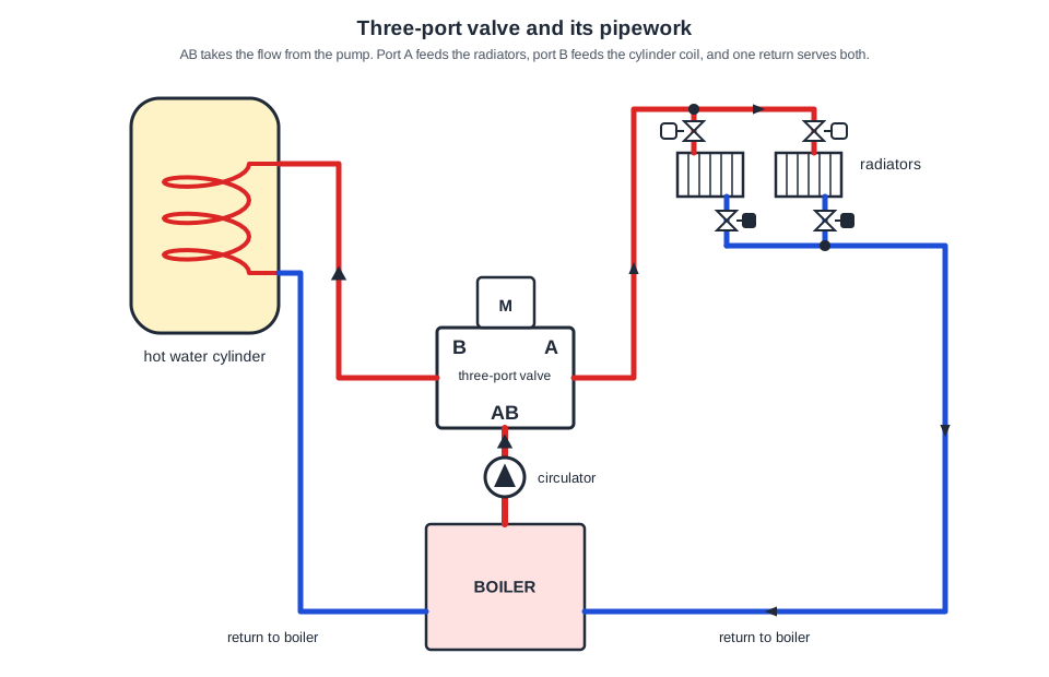
On a three-port mid-position valve AB is the common inlet from the boiler; A serves the heating and B the hot water cylinder.
Y-plan is the system built round a single three-port mid-position valve, which can feed heating, hot water or both at once; it needs no bypass because there is always an open path.
Approved Document L (Volume 1, 2021, paragraph 5.14) requires a new dwelling of 150 m2 or more to have at least two independently controlled heating circuits, each a space heating zone with its own zone valve. Paragraph 5.16 requires a hot water circuit supplied from a store to have its own time control and electronic temperature control, which on an S plan means a third two-port valve. Three circuits in all, of which two are space heating zones: hot water does not count as one.
Going further: the lessons behind this article
This article is the public answer. Unit 333 of the Level 3 course takes the same ground to the depth the exam and the synoptic assignment ask for, in 7 lessons:
- Programmers, thermostats and the wiring centre
- Zone valves: two-port, mid-position and diverter
- S-plan and S-plan plus: two-port valves and separate zones
- Y-plan and W-plan: mid-position against diverter
- Zoning: how many zones, and what each one controls
- Boiler interlock, CHeSS and signing the work off
- Weather compensation, optimum start and home automation
- Central heating systems: the Unit 333 guide — every article on this unit in one place
- All PlumbMate articles — Level 1, 2 and 3
- The Level 3 course — the whole 8202-35 Diploma