A lounge needs 2400 W. There is a radiator in the catalogue rated at 2400 W. Fit it and the room will be cold.
The short answer
That gap between the printed figure and the delivered figure is the whole of emitter sizing, and one line covers it:
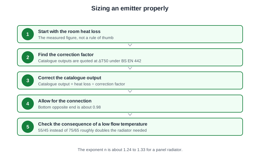
catalogue output = room heat loss ÷ correction factor
Divide, never multiply. A room needing 1000 W with a correction factor of 0.5 needs a catalogue output of 2000 W.
From there the whole design runs in sequence: emitters, then the generator, then flow rates, then pipe sizes, then the pump, then the expansion vessel. Each calculation feeds the next.
Why catalogue outputs need correcting
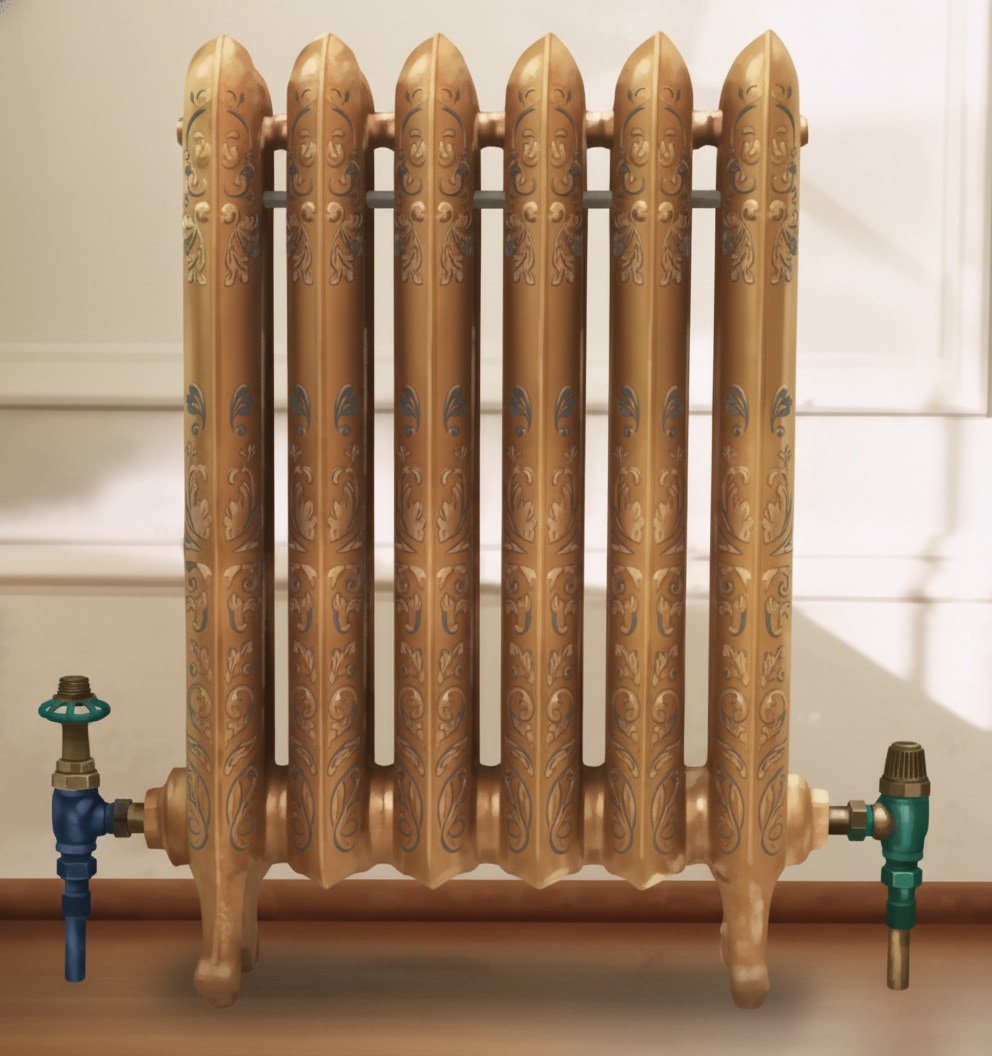
Since July 1997, radiators sold in the EU have been tested to BS EN 442, whose reference condition is 75 °C flow, 65 °C return and a 20 °C room. Mean water temperature is therefore 70 °C, and 70 − 20 gives an excess of 50 K — which is why outputs are quoted at ΔT50. Older data was published at ΔT60, so always check which basis a table uses.
Almost no real system runs at 75/65 into a 20 °C room. The correction depends on the mean water temperature, which is half the sum of the flow and the return, less the room temperature. CIBSE Guide B1 gives output = φ50 × (Δθ ÷ 50)n, where n is around 1.24 to 1.33 for a panel radiator. In practice you take the factor from the manufacturer's table.
The same room, two designs
A 2400 W lounge at 21 °C.
At 75/65. MWT = (75 + 65) ÷ 2 = 70 °C. Excess = 70 − 21 = 49 K. Factor = (49 ÷ 50)1.3 = 0.97.
2400 ÷ 0.97 = 2474 W — call it a 2.5 kW radiator.
At 55/45. MWT = 50 °C. Excess = 50 − 21 = 29 K. Factor = (29 ÷ 50)1.3 = 0.49.
2400 ÷ 0.49 = 4898 W.
A further factor applies for the connections. Radiators are tested top, bottom, same end (TBSE), while most domestic radiators are connected bottom, bottom, opposite end (BBOE), carrying a factor of about 0.98. So 4898 ÷ 0.98 = 4998 W — say a 5 kW radiator.
Same room, same heat loss, and the emitter has doubled. This is the price a low temperature design pays: emitter size, and often pipe size and pump duty with it. The heat still has to get out of the emitter and into the room.
It also explains why the pair of figures matters. Of 50/40, 45/40, 45/35 and 55/45, the highest mean water temperature is 55/45, giving a mean of 50 °C, and therefore the smallest emitters. The others give 45, 42.5 and 40.
Type matters as much as size. In a children's nursery the right choice is a low surface temperature (LST) radiator, because its casing stays cool enough that a child cannot be burnt; column radiators and fan convectors both present hot surfaces. The third connection arrangement, top, bottom, opposite ends (TBOE), is the one recommended for a heat leak radiator on a solid fuel boiler, because it keeps the radiator circulating reliably by gravity when the pump is off.
For a heat pump the emitters rank by how much surface they offer at low water temperature: underfloor, then fan-assisted emitters, then oversized radiators, then standard radiators. Underfloor runs at a mean water temperature around 35 °C. Where underfloor and radiators share one system, an underfloor control pack — blending valve and its own pump — is required. A low loss header solves flow matching, not temperature.
Total heat load and boiler size
The room-by-room work produces two totals doing different jobs: each room's figure sizes that room's emitter; the sum of them sizes the heat generator. Work with the corrected emitter figures, because that is the heat the generator actually has to deliver.
Where hot water is stored, the reheat load has to be added — especially on a hot water priority system, where the heating stops while the cylinder recovers:
kW = (4.19 × litres × ΔT × boiler efficiency) ÷ (time in seconds × 100)
A 240 litre cylinder to 60 °C within 2 hours from an incoming supply at 5 °C, condensing boiler at 93 per cent. ΔT = 55 K. Time = 7200 s.
(4.19 × 240 × 55 × 93) ÷ (7200 × 100) = 7.14 kW
Shorten the recovery time and that figure rises sharply — one of the honest conversations to have with a customer who wants a fast reheat.
Now add the loads and allow for the pipes. With an emitter schedule totalling 10.828 kW:
10.828 + 7.14 = 17.968 kW
Where pipework runs on show in heated rooms, no allowance is needed — its loss warms the room. Where much of it runs under floors and through roof spaces, add 10 to 15 per cent for pipework loss and future extension: 17.968 × 1.15 = 20.67 kW, rounded to 21 kW.
Selection is not only about kilowatts. Check the appliance meets the space heating load, that it meets the hot water load at the flow rate and temperature the household wants, and be honest about combination boilers: they may suit the heating and still disappoint on hot water where there are several outlets or long runs.
The sizing errors
Oversizing is not a safe error. A generator that cannot turn down far enough meets demand too quickly, stops, and restarts — short cycling, which wears the appliance and depresses efficiency. A heat pump 30 per cent larger than the design heat loss will short cycle in mild weather, and cycling can cost about a quarter of the seasonal efficiency. The customer pays more for the unit and then pays more to run it.
Undersizing is expensive differently: the shortfall is met by backup heat at a COP of 1 — direct electric resistance heating, one kilowatt in for one kilowatt out.
And the commonest failure of all is not a calculation error but a missing calculation: replacing a 24 kW combi like for like on a house with a 6 kW heat loss. Nobody worked the building; they read the old badge.
Flow rate and pipe size
Pipes do not carry kilowatts. They carry water, and the heat rides along with it.
flow rate = kW ÷ (ΔT × 4.18)
4.18 is the specific heat capacity of water in kJ/kg°C — not its density and not its latent heat. Some tables use 4.19, which makes no practical difference. Work the bracket first; the answer is in kg/s, which for water is the same number as litres per second.
12 kW at ΔT 5 K: 12 ÷ (5 × 4.18) = 0.57 l/s
Two conversions matter. Multiply l/s by 3.6 to get m³/h, so 1 l/s is 3.6 m³/h. Design sheets use l/s and pump curves often use m³/h, and a mismatch produces answers wrong by a factor of 3.6.
The choice of ΔT changes everything downstream. Boiler systems are designed around ΔT 20 K and heat pump systems around 5 K. Flow rate and ΔT are inversely proportional: double the ΔT and you halve the flow. So a 5 K design needs four times the flow of a 20 K design for the same output — which is why heat pump systems need larger pipework than the boiler system they replace. Not because of pipe material, and nothing to do with the pump curve.
The same relationship is a fault-finding tool. In service, a wide ΔT almost always means restricted flow: the heat is being removed but the water is not moving quickly enough. Look for a blocked strainer, a closed valve, a sludged emitter or a failing pump.
Choosing the pipe, section by section
- Take the heat carried by that section — the sum of everything downstream of it.
- Add a mains loss percentage: as a guide, 5 per cent up to a 10 m run and 10 per cent for a 20 m run, and never less than 5 per cent.
- Convert to a flow rate.
- Read a pipe size from the CIBSE tables, taking the nearest tabulated flow rate above your figure, never below.
- Record the velocity and the pressure loss in Pa/m from the same row — the pump is sized from them.
Two limits govern the choice. Velocity should not exceed 1 m/s for small bore or 1.5 m/s for micro bore, with 1.5 m/s the absolute maximum, because faster water is noisy and erosive; 0.5 to 1 m/s is comfortable. And pressure loss should not exceed about 300 Pa/m in any one section, or the pump will need an unreasonable head.
| Pipe size | Approximate heat carried (20 K design) |
|---|---|
| 10 mm | 3 kW |
| 15 mm | 6 kW |
| 22 mm | 12 kW |
| 28 mm | 22 kW |
Worked example. The section from boiler to the first tee carries the whole 17.968 kW. Add 10 per cent for a 12 m run: 19.765 kW. At ΔT 20 K:
19.765 ÷ (20 × 4.19) = 0.235 kg/s
From the tables that suits 22 mm at 0.75 m/s and 300 Pa/m. It also fits 28 mm at 0.45 m/s and 87.5 Pa/m; 22 mm is cheaper and easier, but it sits right on the pressure limit, so keep it under review until the whole index circuit is worked.
One standard figure to carry: in a fully pumped system, the primary flow and return to an indirect cylinder is normally 22 mm.
Pump duty and the index circuit
The index circuit is the path with the greatest total resistance to flow, normally the longest run to the most remote emitter. It is not the circuit with the biggest heat load. Occasionally a very high resistance terminal on a short branch takes the title, so check rather than assume.
Size for the index circuit and every other circuit follows automatically, because a pump that will push water round the hardest route will manage the easier ones.
For each section you already have the pipe size and the Pa/m. Two more steps:
- Add an allowance for fittings and changes of direction, usually about 33 per cent of the actual pipe length, giving the effective length. A 12 m run becomes 12 × 1.33 = 15.96 m.
- Multiply effective length by the Pa/m: 15.96 × 300 = 4788 Pa.
Total every section on the index circuit — in the worked system, 10 999.1 Pa.
Head is the system's resistance expressed in metres, taken from the index circuit. It is not the pump's maximum output, not the reading on the pressure gauge, and not the static height of the system.
One pascal is 0.000101998 metres head:
10 999.1 × 0.000101998 = 1.122 m head
Then check the appliance. Some low water content boilers put significant resistance through the heat exchanger; the manufacturer gives it, and it is added:
2 m (boiler) + 1.122 m = 3.122 m head
Pump curves are frequently printed in kilopascals, so multiply metres head by 9.81:
3.122 × 9.81 = 30.63 kPa
The duty point is where the flow and the head cross on the pump chart, and you pick the curve on or above it. A curve passing below cannot do the job. If every curve on every speed sits below it, select a different pump or go back and reduce the resistance — usually by increasing a pipe size on the index circuit.
Sizing the pump is not the end, because a pump alone sends water where it is easiest to go. Balancing matches each circuit's flow to its designed output using the lockshields. Equal flow everywhere would starve the emitters that need most and over-serve those that need least. Balancing does not set the pump speed, and it does not remove air.
One safety point. Some central heating pumps hold a small electrical charge after the circuit has been correctly isolated, and the component responsible is the capacitor. Prove dead at the pump, not just at the isolator, and give it time to discharge.
Sizing the expansion
At 4 °C water is at its greatest density — 1 m³ has a mass of 1000 kg. Heat it to 100 °C and that same cubic metre weighs 958 kg: it has grown by about 4 per cent.
On a sealed system the CIBSE method is:
V = eC ÷ (1 − P1 ÷ P2)
- V = vessel volume in litres
- C = total water volume of the system in litres
- P1 = fill pressure in bar absolute (gauge + 1)
- P2 = safety valve setting + 1, also bar absolute
- e = expansion factor: 0.0324 at 85 °C, 0.0359 at 90, 0.0396 at 95, 0.0434 at 100
A system holding 120 litres, filled to 1 bar, safety valve at 3 bar, maximum 85 °C:
P1 = 2, P2 = 4, e = 0.0324. eC = 3.888. 1 − (2 ÷ 4) = 0.5.
V = 3.888 ÷ 0.5 = 7.78 litres
Select the next standard size up — an 8 or 12 litre vessel — never one below the calculation.
Where the maximum temperature is not in the table, the factor comes from the densities: e = (d1 − d2) ÷ d2. For a 600 litre system filled at 10 °C and run at 80: e = (999.8 − 972) ÷ 972 = 0.0286; at 1.5 bar fill and a 6 bar valve, V = 17.16 ÷ 0.643 = 26.68 litres, about 4.4 per cent of system volume.
An open vented system is much simpler: allow 4 per cent of the total system volume as expansion space above the cold fill level. A 400 litre system needs 16 litres. The cistern is sized to take it without discharging through the warning pipe, and fitted at the highest point.
Two arrangements matter with it. The open safety vent must rise at least 450 mm above the water level in the cistern before it turns over, so the pump cannot push water out of it. And it must never be possible to shut off the safety pipe or the feed and expansion pipe.
BS EN 12828 requires at least one safety valve on each heat generator, in an accessible position in the immediate vicinity of the flow pipe, with no isolation valve between the heat generator and the safety valve. The initial system design pressure should be at least the static height pressure plus the vapour pressure, and normally not less than 0.7 bar; the final design pressure should not exceed the safety valve setting minus its shut-off overpressure, typically 10 per cent.
System volume and short cycling
A new heat pump on a small, tightly zoned house starts, satisfies the demand in four minutes, stops, and starts again ten minutes later. All day. Nothing has failed, and yet the installation is a failure.
Short cycling wears the compressor and depresses efficiency. It does not raise the flow temperature or cool the emitters; the damage is to the machine and the running cost. A heat pump wants to run long and low, and it can only do that if there is enough water in circuit to absorb the heat it makes at its minimum output.
Minimum system volume is manufacturer-specific, set against the number of starts per hour the appliance permits. The rule of thumb of 10 litres per kilowatt is a useful first estimate but is not the requirement — the manufacturer's figure governs, and it comes from that appliance's instructions, not a British Standard, not Approved Document L and not a design guide.
Zoning makes this sharper. Volume that disappears when zones close was never volume. A system whose whole content sits behind zone valves has none at all on a mild evening when three of four zones have shut.
When the emitter circuit does not hold enough water, the three devices used are not interchangeable:
- A volumiser sits in series in the flow or return. It simply adds water; everything still passes through it.
- A buffer vessel adds a reservoir the generator can heat and the emitters can draw from.
- A low loss header separates the generator circuit hydraulically from the emitter circuits. It solves flow matching, not cycling — adding one is not by itself a fix for a short cycling appliance.
The buffer arithmetic is straightforward: buffer volume = required total volume − emitter circuit volume. If the appliance requires 215 litres and the pipework and emitters hold 120, the buffer is 95 litres. Never add the two together, and never buy a buffer sized on the total.
How it is connected changes what it does. A two-pipe buffer sits in series: all the water passes through it and the emitters see the generator's flow temperature. A four-pipe buffer separates the two sides, giving hydraulic independence, but the mixing inside it lowers the temperature reaching the emitters. That penalty is real money on a heat pump, and the emitters must then be sized for the lower temperature they actually receive.
Where volume can be added inside the heated envelope, do it: an insulated buffer in a cold garage loses heat to the garage all winter. And the calculation belongs at design stage, not to be discovered at commissioning when the appliance starts cycling in front of the customer.
Flow temperature: the number that governs running cost
A heat pump's work is set by its lift: the gap between the source temperature and the flow temperature it must produce. Widen the lift and efficiency falls, at roughly 2 to 2.5 per cent per kelvin — so dropping a design from 55 to 45 °C flow is worth about 20 to 25 per cent of the running cost. No control setting, tariff or accessory comes close, and it is done at design stage or not at all.
A condensing boiler wants the same thing for a different reason. Flue products from natural gas have a dew point around 55 °C, so the boiler only condenses — and only reaches its advertised efficiency — when the return water is below that.
Two mechanisms, one design answer. And a pair of figures worth holding together: a new dwelling design flow of 55 °C, and a condensing boiler design return of 55 °C. Both are 55, for entirely different reasons.
People misread the 55 °C figure as a setting on the appliance. It is not. The Part L requirement for a 55 °C design flow temperature controls how the emitters are sized at design stage — not the safety cut-out, not the maximum the appliance may produce, and not a commissioning adjustment.
For existing dwellings the requirement is deliberately relative: when a heat generator is replaced, Part L requires the system to be designed to the lowest flow temperature practicable — not a fixed 55, and certainly not whatever the old appliance ran at. The compliance guide's heat pump supply ranges are 30 to 40 °C new underfloor, 30 to 55 existing underfloor, 40 to 55 radiators, 35 to 45 fan coil units.
Only two moves reduce the flow temperature an existing house needs: fabric improvement, and larger emitters. Cut the loss and the existing emitters deliver it at a lower temperature; enlarge the emitters and they deliver the same watts at a lower temperature. A larger pump, wider pipework, a hotter cylinder or a longer heating period do not do it.
In practice a new English dwelling's wall is built to about 0.18 W/m²K, the notional value for the reference dwelling. For comparison, 0.26 is the limiting backstop, 0.30 for an existing wall insulated internally or externally, and 0.55 for an existing cavity being filled. Check the right document for the nation you are working in before quoting any of them.
Presenting the design
The calculations are correct. If they exist only in your head and on the back of an invoice, they are worth nothing: they cannot be checked, priced, defended or handed over.
A finished domestic design normally carries the heat loss calculation tabulated room by room; the emitter schedule; the hot water load and generator size with the allowances shown; the pipe sizing table with flow rates, sizes, velocities and pressure losses; the pump duty and pump selected; the expansion vessel size and the controls; and drawings.
Set the calculations out in tables or a spreadsheet. Laid out in columns, the work can be checked line by line and mistakes show up. Drawings can be to scale or clearly not to scale — a well-drawn schematic is perfectly acceptable for showing what goes where.
Three words are not interchangeable, and confusing them causes disputes:
- A quotation is a fixed price. It is an offer: this work, this specification, this money. Not an estimate that may be revised on completion, not an hourly rate charged as the work proceeds, and it does not disclose the trade price you paid.
- An estimate is an informed approximation that may change, and it must be described as such.
- A tender is a formal priced offer submitted in competition against a specification issued by the client — so the specification, not your interpretation of it, sets the scope.
A quotation should carry the name, address and contact details of the company, say clearly what is included, excluded and assumed, and any variation should be recorded in writing before it is carried out.
The last presentation is the handover. A low temperature system run like an 80 °C system will disappoint. A household used to turning the heating up will find there is nothing to turn up — and if they find the flow temperature setting and raise it, the whole efficiency case disappears. Explain the controls, explain why the radiators feel cool to the hand and the rooms are still warm, and leave the design documents with the customer.
🔢 The numbers worth memorising
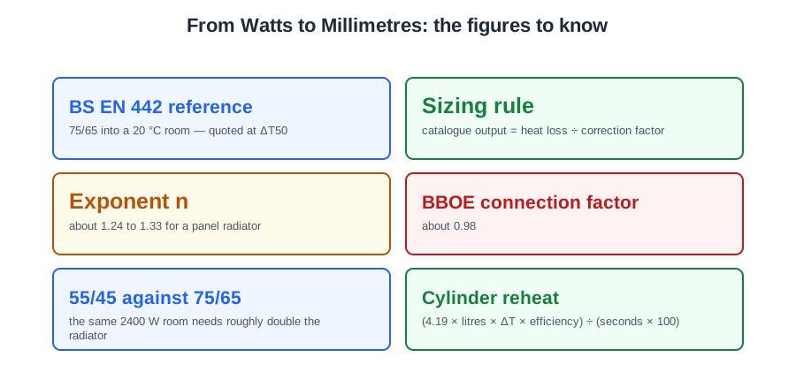
- BS EN 442 reference
- 75/65 into a 20 °C room — quoted at ΔT50
- Sizing rule
- catalogue output = heat loss ÷ correction factor
- Exponent n
- about 1.24 to 1.33 for a panel radiator
- BBOE connection factor
- about 0.98
- 55/45 against 75/65
- the same 2400 W room needs roughly double the radiator
- Cylinder reheat
- (4.19 × litres × ΔT × efficiency) ÷ (seconds × 100)
- 240 l to 60 °C from 5 °C in 2 h
- about 7.14 kW
- Pipework allowance
- 10 to 15 per cent on the generator
- Heat pump 30 per cent oversized
- short cycles in mild weather; cycling costs about a quarter of seasonal efficiency
- Flow rate
- kW ÷ (ΔT × 4.18)
- Unit conversion
- 1 l/s = 3.6 m³/h
- Design ΔT
- 20 K boiler, 5 K heat pump — four times the flow
- Velocity limits
- 1 m/s small bore, 1.5 m/s micro bore maximum
- Pressure loss limit
- about 300 Pa/m per section
- Fittings allowance
- about 33 per cent of pipe length
- Pascals to head
- × 0.000101998; metres head to kPa × 9.81
- Expansion vessel
- V = eC ÷ (1 − P1/P2), both pressures bar absolute
- Expansion factors
- 0.0324 at 85 °C, 0.0359 at 90, 0.0396 at 95, 0.0434 at 100
- Feed and expansion cistern
- space for 4 per cent of system volume
- Open safety vent
- at least 450 mm above the cistern water level
- Minimum system volume
- manufacturer’s figure; 10 l/kW is only a rule of thumb
- Buffer volume
- required total − emitter circuit volume
- Flow temperature
- 2 to 2.5 per cent per kelvin; 55 to 45 saves 20 to 25 per cent
⚠️ Where people go wrong
- Multiplying by the correction factor. Catalogue output = heat loss ÷ factor.
- Reading a ΔT60 table as if it were ΔT50.
- Forgetting the 0.98 connection factor on a bottom-bottom-opposite-end radiator.
- Promising a low temperature design without warning about emitter size.
- Sizing the boiler off the old appliance’s badge instead of the building.
- Treating oversizing as the safe error. It cycles, wears and costs more to run.
- Confusing 4.18 with density or latent heat. It is the specific heat capacity.
- Mixing l/s with m³/h. A factor of 3.6.
- Reusing boiler pipe sizes on a heat pump. At 5 K it needs four times the flow.
- Reading the tabulated flow rate below your figure. Always take the one above.
- Picking the index circuit by heat load. It is the greatest resistance.
- Confusing head with the pump’s maximum output, the gauge reading or the static height.
- Forgetting the boiler’s own resistance when it has a low water content heat exchanger.
- Reading gauge pressures straight into the vessel formula. Both are bar absolute.
- Selecting a vessel below the calculated size.
- Fitting a low loss header to stop short cycling. That is a volume problem.
- Adding the buffer to the emitter volume instead of subtracting.
- Reading the 55 °C design flow as an appliance setting. It sizes the emitters.
- Calling a quotation an estimate, or pricing a tender to your own scope rather than the client’s specification.
📝 10-Question Self-Test
Straight from the Level 3 course question bank. Click an option to see whether you got it right — the explanation appears instantly, and there is nothing to submit.
The label on the cylinder carries the basics. The full technical data, such as coil surface area, recovery rate, standing heat loss and the safety devices fitted, is in the manufacturer’s instructions supplied with that model. Approved Document G is tempting, but it sets the requirements a cylinder must meet, not the performance figures for one particular cylinder.
The system designer. Vessel volume and charge pressure are calculated from the system water content, the fill pressure and the safety valve setting, so that the vessel, the gauge and the relief valve all work together. Change the system volume and the designer’s assumption has changed and the vessel has to be reassessed. The manufacturer’s warranty terms set conditions of use; they do not size anything.
A low surface temperature radiator has a casing around the panel, so the surface a child can touch stays far cooler than the water inside it. That is the whole point of it in a nursery. Cast-iron columns hold a lot of hot water and are a burn risk; fan convectors blow hot air through a grille and offer nothing but hot metal to a small hand.
A low surface temperature radiator. Its casing keeps the touchable surface far cooler than the water inside, which is the protection you need where someone may lean on an emitter and not move away quickly. A cast-iron column holds a large volume of hot water at full flow temperature, and a skirting-height panel radiator is still a bare hot panel at floor level, right where a child is.
Despite the name, a panel radiator gives most of its output by convection, warming the air that passes over it; radiation is the smaller share.
Top, bottom, opposite ends. The National Annex to BS EN 12828 says all the heat a slumbering solid fuel boiler makes should be dissipated, which it allows through a gravity circuit carrying no user-operated valves, so this radiator has to circulate once the pump stops. Feeding the top and returning from the bottom at the far end works with the density difference instead of against it. No standard names the arrangement: TBOE is trade practice, and BBOE, the pumped norm, is far weaker on gravity.
The coefficient of performance is heat output divided by electrical input; a CoP of 3 means three units of heat for one of electricity.
You need two different numbers out of the same exercise. Add every room up and you get the load the boiler or heat pump has to meet; keep the rooms separate and each figure sizes that room’s emitter. Skip the room breakdown and you can still buy a boiler but you cannot size a single radiator. The reversed answer, “the rooms size the unit”, has the two outputs the wrong way round.
Between 4 C and 100 C water expands by about 4 per cent of its volume, which is the figure used to size expansion vessels and feed and expansion cisterns.
Delta (the triangle) means "change in" or "difference", and t is temperature, so delta-t is the temperature difference, as used in heat calculations and radiator sizing.
Going further: the lessons behind this article
This article is the public answer. Unit 333 of the Level 3 course takes the same ground to the depth the exam and the synoptic assignment ask for, in 8 lessons:
- Emitter load: correcting catalogue output to real conditions
- Total heat load, hot water load and the boiler size
- Flow rate and pipe size: from kilowatts to millimetres
- Pump duty: the index circuit, head and the duty point
- Expansion: sizing the vessel and the feed and expansion cistern
- System volume, buffers and short cycling
- Flow temperature: the number that governs running cost
- Presenting the design: schedules, quotations and tenders
- Central heating systems: the Unit 333 guide — every article on this unit in one place
- All PlumbMate articles — Level 1, 2 and 3
- The Level 3 course — the whole 8202-35 Diploma