The screed lorry is booked for Tuesday. On Monday afternoon somebody wheels a barrow of sand across the pipe and puts a wheel rim through it. If the system is under pressure, you find out in ten seconds.
The short answer
The pressure test is carried out before the screed, and the pressure is left on during the pour. That is the whole point: damage shows immediately as a pressure drop, while the screed is still workable and the pipe still reachable. Stop the pour if the gauge moves.
Before that, three constructions and three questions. How much output does the room need, how much build-up depth is available, and how quickly must the floor respond? Those three pull against each other, and every construction is a different compromise between them.
The three constructions
BS EN 1264 shows five standard sections — three solid and two timber. The market summarises them into three. BS EN 1264-4 also groups them by where the pipe sits: Type A has pipes inside the weight-bearing layer, Type B under it, and Type C in an adjustment screed with a second screed poured over.
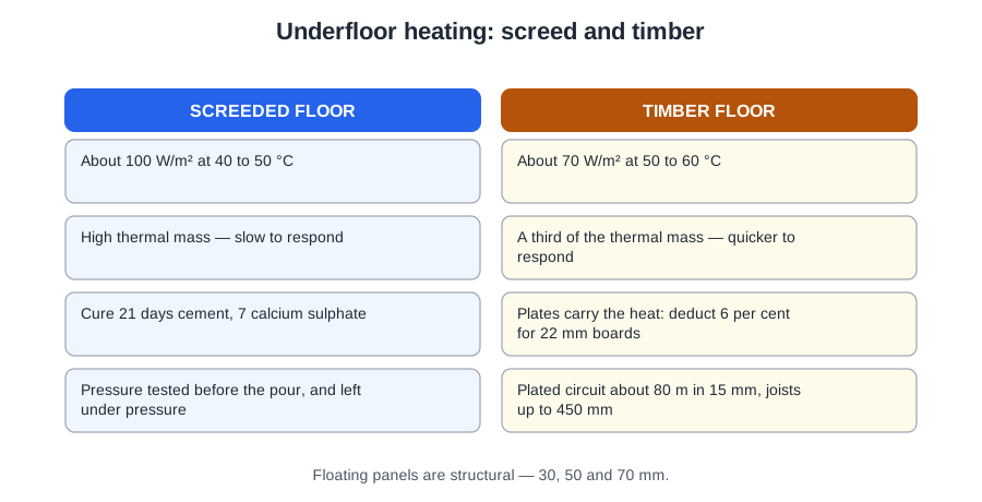
Solid, or screeded. Insulation down, pipe clipped above it, screed over the whole floor. The screed spreads the heat, so the mechanism is conduction through the slab. Most output of the three, typically around 100 W/m², at a design flow of 40 to 50 °C. The price is thermal mass: slow to warm and slow to cool, so the control strategy works in hours, and it is the deepest build-up.
Timber, or intermediate. Pipe runs between the joists in profiled aluminium heat emission plates, or on a reflective foil system. No screed at all. If a section drawing shows pipe in a metal plate between joists, that is a timber floor with an emission plate — foil systems have no plate, and neither floating nor screeded floors show joists. Roughly a third of the thermal mass of a screed, so it responds fastest. Output lower, around 70 W/m², at 50 to 60 °C.
Floating. Grooved insulation panels laid loose on an existing sub-floor, a heat transfer plate in the groove, the pipe clipped into the plate, the finish straight over. In full: floor finish, sub-floor, pipe, heat transfer plate, grooved insulation panels — the only one of the three using both plates and panels. The panels are structural, so their thickness is chosen by the load they carry, which is why they come in 30, 50 and 70 mm. It is the shallowest, which is why it turns up in retrofits and on upper floors.
The cost of a floating floor is a restricted choice of finish. Sheet flooring and strong laminates suit it. Stone requires low deflection: a flat, level base, high compressive strength insulation, and normally a specialist substrate board.
Each construction spreads the heat by a different mechanism, and that decides output, response and how the pipe is held: screed conducts, plates conduct sideways, panels carry.
Joisted floors: the plate is the point
A plated first floor is finished and the customer says the room is warm in strips — you can feel where the pipes are through the carpet. The centres are right and the flow temperature is right. What is missing is the metal.
A joisted floor has no screed to spread the heat, so something has to do it mechanically. The heat emission plate conducts the heat sideways away from the pipe and across the boards. Without it you get warm stripes over the pipes and cold floor between them.
The pipe runs parallel to the joists, sitting in the plate along the bay — which is also why the return bends at the ends of each bay have to be allowed for. Where pipe must cross the joists, they are drilled in accordance with the Building Regulations.
Fit 100 mm mineral wool between the joists, below the plates, for two reasons: to cut the downward heat loss, and for sound. That applies to plated and foil systems alike.
Getting the output figures right
Heat emissions for a plated floor are quoted for the active heated aluminium area alone — not the gross room area, not the area including the joists, and not the area of the finish over the top. So deduct the joists and the return bend spaces. Active area is usually not less than 80 per cent of gross, but check the layout rather than assume.
Two adjustments then apply to both plated and foil figures:
- Deduct 6 per cent for 22 mm boards. Published figures assume 18 mm.
- Deduct 5 per cent for polybutylene pipe. The figures otherwise hold across most 16 to 20 mm pipe.
A foil system works differently: emissions are quoted for the active reflective foil area, and no deduction is normally required unless areas are genuinely unheated. Plated needs deductions, foil does not.
And one place a foil system must not go: over a ventilated void. A reflective system depends on a still layer of air under the boards, and cold air moving through a suspended ground floor void disrupts it and takes the output away.
Cutting the plates
Plates come scored so they can be shortened on site, typically a third from one end and a sixth from the other. Lay the plate over a straight edge with the groove uppermost and snap it sharply on the score line, then clean off the burrs in the pipe groove — a burr will damage the pipe you are about to push into it.
If you need a length the score lines do not give: score the plate deeply, then hacksaw along the groove, and clean the burrs off. Do not snap at the nearest line and accept it, and do not attack the profile with a grinder or snips.
Typical plated figures: about 70 W/m² maximum output, 50 to 60 °C design flow, a maximum circuit of about 80 m in 15 mm pipe, and up to 17 m² per circuit at 225 mm centres using a double spreader plate. Suits joist widths up to 450 mm.
The layers before the screed
A screeded floor a year old, running costs far above the estimate. The pipe centres are right and the boiler is right. When the extension is dug, the section shows why: the insulation was laid, but the polythene over it was skipped and the wet screed ran into every board joint.
In a solid floor the insulation goes below the pipe and above the damp proof membrane. That order is the whole point — every kilowatt that goes downwards is one the customer paid for and never felt. On a section drawing the insulation is marked by its hatched British Standard symbol; learn to read it, because on a busy detail the layers are only distinguished by hatching.
For a ground floor the target is a U-value of 0.25 W/m²K, in practice about 75 mm of PIR or 110 mm of EPS. Confirm it on the particular job, because the target and the make-up vary with the rest of the floor.
Which regulations apply depends on where the property is: Part L and Part E in England and Wales, technical booklets F and G in Northern Ireland, sections 6 and 5 in Scotland. Do not confuse the letters: Part L is conservation of fuel and power, Part E is sound, Part P is electrical safety. Floor insulation has nothing to do with Part P.
One trap with a floating floor: a structural grooved panel 50 mm thick does not automatically satisfy Part L. Its thickness was chosen for the load it carries, not for a U-value. Check the U-value for the whole build-up and expect to add insulation beneath it.
The polythene and the edge strip
Before the screed, the insulation is covered with a protective layer: BS EN 1264-4 clause 4.1.2.3 calls for a polyethylene film at least 0.15 mm thick with minimum 80 mm overlaps. Its job is simple — wet screed running into the insulation joints ruins the insulation value. Note this protective layer is not a damp proof membrane; the DPM is a separate layer, lower down.
Clause 4.1.2.2.2 requires a peripheral insulating strip placed before the screed is laid, along the walls and along every other building component that penetrates the screed — door frames, pillars and risers. Anything rigid the slab could push against needs it: every perimeter, column and threshold, not just the outside walls.
It does two jobs: it is a thermal barrier, stopping heat passing into the surrounding walls, and it leaves an expansion gap so the heated slab can move — at least 5 mm. It must rise from the supporting base to the upper edge of the finished flooring, be firmly secured, and only be trimmed flush after the floor covering is complete. A strip that stops below the finish is a cold bridge.
Of everything in a solid floor, the two layers most often left out on site are exactly these: the polythene over the insulation and the edge strip. Neither shows once the floor is down, and both cause trouble later — wet insulation, and a slab with nowhere to expand.
First fix: the order of work
Two hundred metres of tube on site and the joiner about to board out. Nothing can be laid yet, because the manifold has not been fixed and nobody has agreed where the thermostats go.
The sequence starts away from the pipe. Wiring first, then services, then fix the manifold — before the tube goes down. Laying pipe towards a manifold position that has not been fixed is how tails end up three metres short. Then lay the insulation, run the tube, and connect.
Site the manifold as centrally in the property as possible, for two reasons: shorter tails, and less uncontrolled heat from tails crossing rooms that are not calling for heat. Two insulated primaries cope with distance far better than a dozen uninsulated tails.
A central position also evens out the circuits. Water takes the line of least resistance, so short circuits are always served first, and the system is only as good as its slowest circuit. Where pipework congests around the manifold the area can become a hot spot — insulate the pipework around the manifold until it enters the room it serves.
Keep it accessible, because things happen there for the life of the system: flow meters are read, lockshields are set, actuators are replaced. Allow room for the whole assembly, and allow height as well as width — a manifold set too low leaves no room to get a hose on the drain-off, one set too high puts the automatic air vent out of reach.
As each circuit is connected, label the port with the room it serves. A manifold with twelve unlabelled loops is a fault-finding problem waiting to happen, and labelling costs nothing at first fix.
Store the tube dry and out of sunlight, away from sharp objects and chemical spillage, and allow no soldering near it. If the tube may freeze before or during installation, add antifreeze and flush it out afterwards — the same applies while the screed is drying. A frozen circuit under a new screed is not a repairable situation.
The trade that most needs your information at first fix is the electrician, because the thermostat positions decide the cabling. Wire the stats into the wrong rooms and the fault stays invisible until commissioning. The site rule: trades involved are briefed and fully conversant with the layout; trades not involved are notified and kept out. Not everybody needs the design — but everybody needs to know there is pipe in that floor.
Laying the pipe
A solid screed floor takes 16 mm barrier pipe. The barrier matters more than the size: oxygen diffusing through a non-barrier wall corrodes every ferrous component and makes the sludge that eventually blocks a manifold. Non-barrier pipe is cheaper and more flexible, and it is the wrong choice.
Pipe is laid in one continuous length without joints, which is why it comes on coils of up to 100 m.
The first pipe run goes at least 100 mm off the wall — any closer and you heat the wall, not the room, with nothing left for the edge strip either. BS EN 1264-4 puts it as pipes placed more than 50 mm from vertical structures and more than 200 mm from smoke ducts, open fireplaces, shafts and lift wells. The perimeter band still runs at 150 mm centres, because that is where the loss is.
Centres across the room follow the heat requirement, typically 100, 200 or 300 mm. As a guide for a solid floor, one circuit covers about 12 m² at 100 mm, 22 m² at 200 mm and 30 m² at 300 mm, using 8.2, 4.5 and 3.3 metres of pipe per square metre. Maximum circuit about 100 m in 15 mm pipe. Do not run pipe under kitchen or utility units.
All of the usual fixing methods are acceptable — clips or staples into the insulation, clip rails, matrix overlays, or fixing to reinforcement mesh. What matters is the result. Clause 4.1.2.7 requires the pipe position to be held as planned: vertical deviation upwards not more than 5 mm, and horizontal deviation of the specified spacing within ±10 mm at the attachment points. In practice individual fixings need to be about 500 mm apart.
Bring the pipe to shape by pulling it, never forcing it. A twisted pipe fights you the whole way round the room and sits proud when you let go. The print line along the pipe shows you the twist — watch it and let the coil unwind rather than dragging it flat.
The rule below ground is no joints, though accidental damage may be repaired. Where a repair is made, the joint must be exactly located and recorded on a record drawing in the building log book.
Where pipe crosses a screed joint or a doorway, fit a conduit sleeve for 400 mm either side, fixed so it cannot migrate when the screed goes in. The conduit lets the two slabs move independently without shearing the pipe.
At the manifold, cut the pipe square, with a plastic pipe cutter, leaving no burrs. A clean cut at right angles is what makes the compression connection seal; a hacksaw, a file or side cutters will not give it.
The test, the pour and the cure
Clause 4.1.3 requires that, prior to laying the screed, the heating circuits are checked for leaks by a pressure test using water or compressed air. Not less than 4 bar and not greater than 6 bar, with the absence of leaks and the test pressure recorded in a test record.
A common working procedure: flush each circuit with mains water from the flow manifold drain-off to the return manifold drain-off until it runs clear and the air is out; connect a hydraulic test pump and raise the system to 6 bar for one hour; then reduce to 3 bar and lay the screed over the top.
Immediately before the screed arrives, walk the floor and check the edge strip is standing and the conduits are in place. Both get kicked out of position during first fix, and neither can be put right once the screed is down.
Board out the walking and barrow routes — the standard says the same: boards should be laid when carting screed mortar over the pipe system, and short-term heavy loads on the insulating layer must be avoided. Never walk or barrow directly on the pipe or the insulation.
Screed and room temperature must not fall below 5 °C when laying, and must be kept at at least 5 °C for not less than 3 days; the cement screed is protected from drying out for at least 3 days.
Depth, measured from the top of the insulation: a floating sand and cement screed is at least 65 mm in a dwelling and 75 mm for heavier loads (BS 8204-1), with at least 30 mm over the pipe (BS EN 1264-4). Thinner than 65 mm, or a flowing calcium sulphate screed, is to the screed maker’s figure. Depth is a genuine trade-off, not a case of going thicker. Too thin and the screed cracks and gives striped output; too thick and you add thermal lag you can never remove.
Commissioning waits 21 days after the pour, and you must never use the heating to dry the screed. Forcing the moisture out drives cracking. Clause 4.1.4 gives 21 days for cement screeds, 7 for calcium sulphate, 1 for gush asphalt, and then sets the heat-up: begin at 20 to 25 °C held for at least 3 days, then the maximum design temperature for at least a further 4 days, all documented.
The two facts that most affect the site programme are exactly these: the 21 day cure, and that heat cannot be used to dry it. Three weeks of doing nothing sits badly with a builder's programme, which is why it goes in front of them in writing at first fix, not the week the screed goes down.
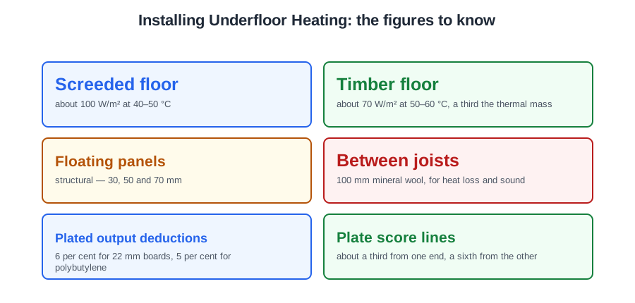
🔢 The numbers worth memorising
- Screeded floor
- about 100 W/m² at 40–50 °C
- Timber floor
- about 70 W/m² at 50–60 °C, a third the thermal mass
- Floating panels
- structural — 30, 50 and 70 mm
- Between joists
- 100 mm mineral wool, for heat loss and sound
- Plated output deductions
- 6 per cent for 22 mm boards, 5 per cent for polybutylene
- Plate score lines
- about a third from one end, a sixth from the other
- Plated circuit
- about 80 m in 15 mm; joists up to 450 mm
- Ground floor U-value
- 0.25 W/m²K — about 75 mm PIR or 110 mm EPS
- Protective film
- 0.15 mm, 80 mm overlaps — not a DPM
- Edge strip
- at least 5 mm movement; trimmed only after the finish is down
- Screed pipe
- 16 mm barrier pipe, one continuous length
- First run off the wall
- 100 mm; perimeter band at 150 mm centres
- Pipe position tolerance
- 5 mm vertical, ±10 mm horizontal; fixings about 500 mm apart
- Conduit sleeve
- 400 mm either side of a joint or threshold
- Pressure test
- 4 to 6 bar, recorded; 6 bar an hour, then pour at 3 bar
- Screed depth
- 65 mm above the insulation in a dwelling, 75 mm for heavier loads; 30 mm over the pipe
- Cure
- 21 days cement, 7 calcium sulphate, 1 gush asphalt
⚠️ Where people go wrong
- Laying a joisted floor without emission plates. You get warm stripes and cold floor between.
- Quoting plated output on the gross room area. It is the active aluminium area, minus joists and return bends.
- Forgetting the 6 per cent and 5 per cent deductions on a plated floor.
- Using a foil system over a ventilated void. Moving air takes the output away.
- Grinding a plate to length. Score deeply and hacksaw the groove, then deburr.
- Skipping the polythene over the insulation. Wet screed in the joints ruins its value.
- Running the edge strip only to the outside walls. Every perimeter, column and threshold.
- Trimming the edge strip before the floor covering is down. It becomes a cold bridge.
- Assuming a 50 mm structural panel satisfies Part L. Its thickness was chosen for load.
- Laying pipe before the manifold is fixed.
- Using non-barrier pipe. Oxygen through the wall corrodes every ferrous component.
- Running the first pipe tight to the wall. You heat the wall, not the room.
- Forcing a twisted pipe into shape instead of pulling it and letting the coil unwind.
- Making an unrecorded joint under a floor.
- Testing after the pour, or dropping the pressure before it. Leave it on.
- Barrowing over the pipe or the insulation.
- Heating the screed to dry it, or commissioning before 21 days.
📝 10-Question Self-Test
Straight from the Level 3 course question bank. Click an option to see whether you got it right — the explanation appears instantly, and there is nothing to submit.
Flat rubber washers, supplied with the pump and with the valve set. The flanged union nut squeezes the washer between two machined faces, so the seal is made by compressing the washer, not by anything on the thread. PTFE tape wound round the flange does nothing there, and fibre washers with paste or hemp and compound belong to threaded joints, not to a union face.
The standard floor sections summarise into three in practice, and the manufacturer specifications are all built on them: solid or screed, timber or intermediate, and floating.
The profiled aluminium plate is the tell. Foil has no plate, floating has no joists, screed has no joists either.
A timber floor is roughly a third of the thermal mass of a screed, which is exactly the trade being made.
Every kilowatt that goes downwards is one the customer paid for and never felt.
Neither shows once the floor is down, and both cause trouble later — wet insulation, and a slab with nowhere to expand.
Figures assume 18 mm boards, and hold across most 16–20 mm pipe except polybutylene.
Cold air moving through a suspended ground floor void disrupts the still-air layer the system depends on.
Emissions are quoted for the active reflective foil area, and deductions are not normally required.
Which is why they come in 30, 50 or 70 mm and why extra insulation is very often needed underneath for Part L.
Going further: the lessons behind this article
This article is the public answer. Unit 333 of the Level 3 course takes the same ground to the depth the exam and the synoptic assignment ask for, in 6 lessons:
- The three underfloor floor constructions compared
- Joisted floors: emission plates, foil and output figures
- Floor insulation and the layers before the screed
- First fix: the manifold, the sequence and other trades
- Laying the underfloor pipe: centres, fixing and joints
- The pressure test, the pour and the 21 day cure
- Central heating systems: the Unit 333 guide — every article on this unit in one place
- All PlumbMate articles — Level 1, 2 and 3
- The Level 3 course — the whole 8202-35 Diploma