A customer stands in a new extension and tells you the underfloor heating is broken, because the floor is barely warm to the hand. It is working perfectly.
The short answer
Everything about underfloor heating follows from one trade: a very large emitter running at a very low temperature.
A radiator is perhaps a square metre of surface at 70 to 80 °C. A heated floor is the whole room — an emitter roughly twenty times larger — so each square metre has to work far less hard. That is why it runs at much lower water temperature, and lower water temperature is exactly how it cuts energy consumption.
Four facts carry the rest: big emitter, low temperature, slow response, capped surface.
The temperatures, and the hard ceiling on output
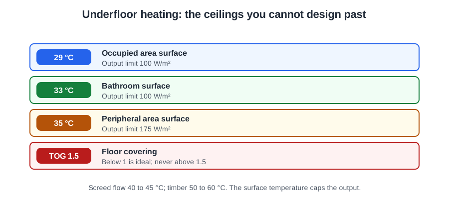
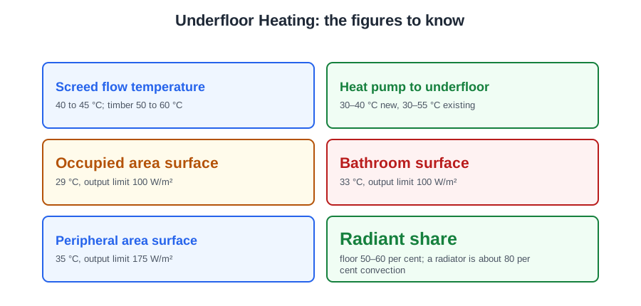
Typical design flow temperatures are 40 to 45 °C for a screeded concrete floor and 50 to 60 °C for a timber construction, where the heat has to cross a spreader plate and a board. For a heat pump, the compliance guide gives 30 to 40 °C in new buildings and 30 to 55 °C in existing systems.
Stand-alone underfloor heating therefore calls for the lowest boiler flow temperature of any wet emitter arrangement — and low return temperatures are precisely what a condensing boiler and a heat pump both want.
You cannot simply make a floor hotter, because people walk on it. BS EN 1264-2 fixes the limits:
| Area | Maximum surface temperature | Room temperature | Limit output |
|---|---|---|---|
| Occupied area | 29 °C | 20 °C | 100 W/m² |
| Bathroom and similar | 33 °C | 24 °C | 100 W/m² |
| Peripheral area | 35 °C | 20 °C | 175 W/m² |
The peripheral area is the strip along an outside wall or under a window where the pipes are laid closer together; nobody stands there for long, so a higher surface temperature is allowed. Everywhere else the surface is capped at 9 K above the room temperature.
The consequence is the single most important design fact about the technology. Output has a hard ceiling. If the heat loss of a room exceeds what the floor can give, no adjustment on site will fix it — and the circuits are buried in screed by the time anybody finds out. Underfloor heating has to be designed against a proper room-by-room heat loss, not estimated.
What it is genuinely good at
A radiator gives about 80 per cent of its heat as convection, producing a plume of hot air at the ceiling, a cool floor and a draught along it. A heated floor works by conduction into the structure and then radiation — around 50 to 60 per cent radiant — and it comes closest of any system to the ideal comfort profile: warm feet and a cooler head. In a room with a high ceiling that matters even more, because radiant heat stays where the people are instead of rising.
- Even temperature with no cold spots, and no hot surface — a 29 °C floor cannot burn a child or an elderly person.
- Total freedom of furniture layout: nothing on the walls, no decorating behind emitters and no staining above them.
- Reduced air movement, so less airborne dust and fewer mites; the floor covering is also drier, which discourages house dust mite.
- Fewer leaks: a buried circuit is one continuous pipe with no connections along its length, and most heating leaks happen at radiator tails and valve connections.
- Very low maintenance, near-silent, and it suits micro-renewables and heat pumps.
The limitations belong in the survey conversation, not the handover. The floor is a thermal mass: it steadies the room temperature and makes the system slow, responding over hours rather than minutes. A screed is a poor choice for a spare room used twice a month; timber responds faster. And the floor covering is constrained — coverings should have a TOG rating below 1 and never above 1.5, covering and underlay together (BS EN 1264), because a thick carpet and underlay simply trap the heat.
The one thing that is never an advantage is rapid response, and any customer who has been told underfloor runs hotter than radiators has been told the opposite of the truth.
Pipework: patterns, spacing and the pour
The screed is booked for Thursday. Everything you do before that pour is permanent.
Underfloor heating uses continuous pipe laid without joints, delivered on drums of up to about 100 m so a whole room can be covered in one length. The material is normally PE-X, PB, PE-RT or multilayer pipe with an oxygen barrier; copper to EN 1057 in the annealed R220 temper may also be used. BS EN 1264-4 requires the pipe to be selected for an operating pressure of at least 4 bar and a 50 year life.
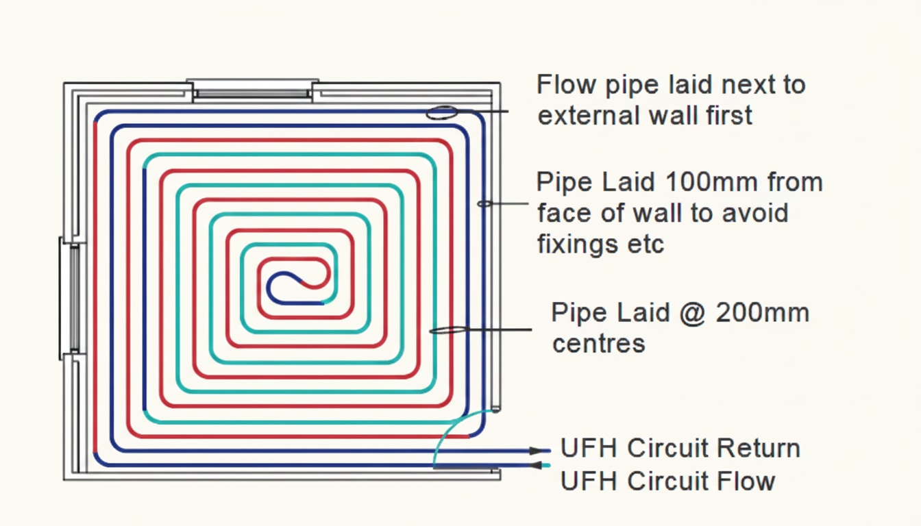
- The series pattern (meander, serpentine): the flow runs first to the coldest part of the room, usually the window wall, then back and forth at the design centres. It gives an average temperature across the floor where the pipe runs are long, and suits areas of high heat loss.
- The snail pattern (bifilar, spiral): the flow spirals inwards, then reverses and returns in parallel between its own runs, so flow and return alternate across the floor and the surface temperature is very uniform. Used under hardwood and vinyl, which dislike temperature variation.
Pipe is laid at centres of typically 100, 200 or 300 mm, tighter in peripheral areas and rooms with high heat loss. Manufacturers publish the coverage: for a solid floor, around 12 m² at 100 mm, 22 m² at 200 mm and 30 m² at 300 mm per circuit — with a maximum circuit length of about 100 m in 15 mm pipe on a solid floor and about 80 m on suspended timber. Do not lay pipe under kitchen or utility units, and drill joists to the Building Regulations where pipe has to cross them.
Insulation and the protective layer
Insulation under the pipe is not optional: without it a large share of the output goes downwards. BS EN 1264-4 Table 1 sets minimum heat conduction resistance for the insulating layer:
- 0.75 m²K/W with a heated room below.
- 1.25 m²K/W over an unheated or intermittently heated room, or directly on the ground.
- 1.25, 1.50 or 2.00 m²K/W where external air is below or adjacent, depending on the external design temperature.
The compliance guide adds that downward heat loss through an exposed ground floor should be limited to not more than 10 W/m². Boards are butted tightly and multiple layers staggered so the joints do not line up.
Around the edge of every room a peripheral insulating strip is fixed before the screed. It runs from base to finished floor surface and must allow the screed at least 5 mm of movement. Over the insulation goes a protective layer of polyethylene film at least 0.15 mm thick with 80 mm overlaps.
Supports depend on the construction: castellated panels the pipe is walked into, clip rails, staples into insulation, or aluminium heat spreader plates between joists at up to 450 mm centres on suspended timber.
The pressure test, the screed and the first heat-up
The pressure test is carried out before the screed is laid, and the whole point is that it cannot be repeated afterwards. BS EN 1264-4 requires a test pressure of not less than 4 bar and not more than 6 bar; in practice the system is taken to 6 bar and held for one hour, then dropped back to about 3 bar and left under pressure while the screed is poured, so that any damage shows itself immediately.
Cover over the pipe is at least 30 mm of cement screed, and the screed and the room must not fall below 5 °C during laying or for at least 3 days afterwards. The maximum temperature around the pipes must not exceed 55 °C for cement or calcium sulphate screed — which is why the manifold has a high limit cut-off.
Then the part everybody wants to rush. The initial heating up starts only after 21 days for a cement screed, 7 days for calcium sulphate, or 1 day for gush asphalt. It begins at a flow temperature of 20 to 25 °C held for at least 3 days, after which the maximum design temperature is set and held for at least a further 4 days.
The manifold
The floor circuits in a new build are barely warm. You open the manifold cupboard and find the flow meters all reading differently, the blending valve still on its factory setting and no record of any commissioning. Almost everything that goes wrong with underfloor heating goes wrong at the manifold.
BS EN 1264-4 says the manifold shall be placed so as to give the shortest flow pipes, because long flow pipes give away heat that no room control can switch off. In practice that means as centrally in the dwelling as possible, which also equalises the circuit lengths and makes balancing achievable — a system is only as good as its slowest circuit. Insulate the congested pipework around the manifold, or the cupboard becomes a hot spot.
A manifold is a pair of bars, flow and return, with a job for each part:
- Flow meters on the flow bar indicate the flow rate in each circuit.
- Lockshields regulate it. The meters tell you what you have; the lockshields change it.
- Thermal actuator heads on the return bar switch each circuit, opened and closed by that room's thermostat.
- Manifold isolation ball valves at the ends of both bars let the manifold be shut off without draining the system.
- An automatic air vent at the high point, a temperature gauge on each bar and drain-off points complete the core assembly.
BS EN 1264-4 in standards language: each circuit shall have two stop valves and a balancing device, with shut-off and balancing independent, and at least one circuit per heated room.
Blending: how the floor gets cool water
Primary water arrives at 70 to 80 °C and the floor is only allowed 40 to 45. Two ways of bringing it down:
- A three-port thermostatic mixing or blending valve blends hot primary flow with cooled circuit return water.
- A two-port injector valve works from the other direction: it meters a controlled amount of hot primary water into a circuit that is otherwise recirculating.
Both are pumped assemblies. The manifold pump sits between the blending valve and the flow bar. Control is by a sensor and a thermostatic head: if the sensor reads hotter than the head allows, the injector closes and the water simply recirculates round the floor circuits, cooling, until it is low enough for the injector to open again. That cycle is what holds the temperature down.
Two more valves go with the control strategy. A differential pressure valve regulates the pressure across the manifold so flow rates can be set and stay set — without it, closing one circuit changes the flow through all the others and balancing never converges. And an automatic bypass is needed on any room-controlled system, because every zone will eventually be satisfied at once and the manifold pump must not be left dead-heading.
The safety cut-off
Blending can fail. BS EN 1264-4 requires a safety device, independent of the control unit, that operates even in the absence of electrical power, cutting off the heat supply so the temperature around the pipes cannot exceed the screed limit.
On a domestic manifold that is the high limit thermostat — the last line between a boiler at 80 °C and a screed that is only allowed 55 °C around the pipe. If the thermostatic head fails on a system fitted with it, the pump stops and water bypasses the circuits, passing from the injector to the lockshield without going through the floor, so primary temperature never reaches the screed.
The compliance guide requires the same: flow water from a high temperature (60 °C) heat source is controlled by multi-port mixing valves with thermo-mechanical or thermo-electric actuators, plus a separate high limit thermostat. It also asks that each room has its own thermostat, sensor or programmable thermostat, though two adjacent rooms with a similar function, such as a kitchen and a utility, may share one. Those room thermostats are the item mounted 1.5 m above the floor; the floor sensor sits in the floor and the flow meters stay on the manifold.
And a factory-assembled pump and blending package does not commission itself. The blend temperature still has to be set and recorded, and the flow rates balanced on the meters.
Underfloor with radiators
An extension is going on the back of a 1990s house. The extension has underfloor heating, the rest keeps its radiators, both from the same boiler. The floor wants 40 to 45 °C and the radiators want 70. That difference is the whole design problem, and it is not solved by wishing.
Underfloor work falls into three categories:
- Full house — underfloor throughout, room-by-room control, heat source running at the low temperature all the time.
- Extension — underfloor in the new part, radiators in the old. An extension system is always a mixed temperature system, which is why the blending arrangement is never optional.
- Single or one zone — a conservatory or bathroom, controlled by a return temperature limiter. Cheapest and simplest, and correspondingly limited: there is no room-by-room control.
Every manifold must be served from the primary flow and return of the central heating source — not a cylinder draw-off, not a secondary hot water circuit, not a collector array.
Three checks on the existing system belong on the survey, and they are the first things to look at when a finished system will not get heat to the manifold: boiler size, primary pipe size and primary pump size. An extension adds load, and a 15 mm primary that suited four radiators will not carry the extra.
Insulate the primary pipework between the boiler, the cylinder and the manifold. The reason is simple and often missed: the heat from a primary cannot be switched off by any room control, so a hot primary crossing a heated zone is warming that zone whether it wants it or not.
Running two temperatures
There are two honest answers: run the whole system at the radiator temperature and blend down at the manifold, or run separate zones at separate temperatures, each with its own control. The compliance guide adds a third worth raising with the customer: a mixed system on a common high temperature heat source may benefit from running at the same low water temperature throughout, if the radiators are large enough to give their output at that temperature.
Whichever you choose, the efficient arrangement is to time-switch the radiators independently of the underfloor. The two have completely different response times: radiators can come on for two hours in the evening while the floor, which takes hours to warm and hours to cool, runs its own longer schedule. Running both circuits on one time channel wastes the advantage of each.
Zone the two with two-port motorised valves and give each its own time control. Dwellings under 150 m² should have at least two space heating zones with independent temperature control, one assigned to the living area; dwellings of 150 m² or more, two zones with independent on/off time and temperature control. A thick screed system, 65 mm or more, should have facilities for automatic setback at night or when the house is empty — the mass is too slow to be simply switched off.
🔢 The numbers worth memorising
- Screed flow temperature
- 40 to 45 °C; timber 50 to 60 °C
- Heat pump to underfloor
- 30–40 °C new, 30–55 °C existing
- Occupied area surface
- 29 °C, output limit 100 W/m²
- Bathroom surface
- 33 °C, output limit 100 W/m²
- Peripheral area surface
- 35 °C, output limit 175 W/m²
- Radiant share
- floor 50–60 per cent; a radiator is about 80 per cent convection
- Floor covering
- TOG below 1, never above 2.5
- Pipe selection
- at least 4 bar, 50 year life
- Pipe centres
- 100, 200 or 300 mm
- Maximum circuit
- about 100 m solid floor, 80 m suspended timber
- Insulation resistance
- 0.75 over a heated room, 1.25 m²K/W over unheated or on the ground
- Downward loss limit
- 10 W/m² through an exposed ground floor
- Edge strip movement
- at least 5 mm
- Protective film
- 0.15 mm thick, 80 mm overlaps
- Spreader plates
- up to 450 mm centres
- Pressure test
- 4 to 6 bar before the screed; hold 6 bar an hour, pour at about 3
- Screed cover
- at least 30 mm; never above 55 °C around the pipe
- First heat-up
- after 21 days cement, start at 20–25 °C for 3 days, then design for 4
- Setback threshold
- screed 65 mm or more
⚠️ Where people go wrong
- Promising a customer that underfloor is fast. Slow response is inherent — it is a thermal mass.
- Telling a customer the floor should feel hot. 29 °C is the cap in an occupied area.
- Estimating the heat loss. Output has a hard ceiling and the circuits are buried before anyone finds out.
- Fitting a thick carpet and underlay over a heated floor.
- Laying pipe under kitchen units.
- Pressure testing after the screed. It cannot be repeated — test before.
- Heating a cement screed before 21 days, or starting at the design temperature.
- Confusing the manifold parts: meters indicate, lockshields regulate, actuators switch.
- Leaving a factory blending package on its factory setting. Set and record the blend temperature.
- Omitting the high limit thermostat. It is the device that works with no power at all.
- Feeding a manifold from a cylinder draw-off or secondary circuit. It comes off the primary flow and return.
- Running the radiators and the floor on one time channel. Their response times are nothing alike.
📝 10-Question Self-Test
Straight from the Level 3 course question bank. Click an option to see whether you got it right — the explanation appears instantly, and there is nothing to submit.
The serpentine, or meander, pattern takes the flow first to the coldest part of the room, usually the window wall, then runs back and forth across the floor at the design centres. Because the water cools steadily along one long path, the surface settles at an average temperature. The spiral or snail pattern is the one that gives a uniform surface temperature, by pairing flow and return pipes side by side.
The floor is an enormous emitter, so it gives its design output at around 40 to 45 °C where a radiator needs about 70 °C. The lower flow temperature cuts distribution losses and lets a condensing boiler or heat pump work at its efficient end. Heating the air is tempting, but underfloor works mainly by radiant heat off the floor surface.
The two emitters respond at completely different speeds: radiators warm a room in minutes, while a screeded floor takes hours to warm and hours to cool. Giving each its own time channel lets the floor run on a long early schedule and the radiators come on only when rooms are in use. Running both on one channel throws away the advantage of each.
Underfloor heating spreads its output over the whole floor area, so it reaches design output at about 40 to 45 °C. Standing alone, nothing else on the circuit demands a higher temperature, so the boiler can run at its lowest flow temperature and condense hard. Fan convectors are the tempting pick, but they need high temperature water to give their rated output.
The room thermostat is the one underfloor control mounted on the wall, about 1.5 m above the floor, clear of draughts, direct sunlight and other heat sources so it reads the room fairly. The floor temperature sensor is the tempting answer, but that sits down in the screed beside the pipe, and the blending valve and flow meters both stay on the manifold.
The circuits are tested before the screed goes on, because once it is poured a leak is buried. BS EN 1264-4 clause 4.1.3 requires a test pressure of not less than 4 bar and not more than 6 bar for standard systems; it sets no hold time, and the hour is trade and textbook practice rather than a figure the standard gives. The pipes stay under pressure while the screed is laid, and fifteen minutes is too short to show up a slow weep.
The floor wants 35 to 45 °C and the radiators want more. Either run the whole system at the radiator temperature and blend down for the floor, or run separate zones at separate temperatures.
Big emitter, low temperature. Every rule in this course is a consequence of that trade.
Low return temperatures are what a condensing boiler and a heat pump both want, and a 29 °C floor cannot burn anybody.
A radiator produces close to the opposite: a plume of hot air at the ceiling, a cool floor, and a draught along it.
Going further: the lessons behind this article
This article is the public answer. Unit 333 of the Level 3 course takes the same ground to the depth the exam and the synoptic assignment ask for, in 4 lessons:
- Underfloor heating: floor temperatures, output and comfort
- Underfloor pipework: patterns, insulation, screed and testing
- The underfloor manifold: blending, balancing and safety
- Underfloor with radiators: mixed temperature systems and zones
- Central heating systems: the Unit 333 guide — every article on this unit in one place
- All PlumbMate articles — Level 1, 2 and 3
- The Level 3 course — the whole 8202-35 Diploma