You are in an airing cupboard with a new wiring centre on the wall and one existing accessory to feed it from: a small plate with a switch, a neon and a fuse carrier.
The short answer
That accessory is a fused connection unit, and every volt the heating controls ever see passes through it.
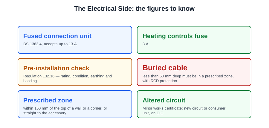
Two figures go with it and they are constantly confused. The accessory is built to BS 1363-4 and accepts a cartridge fuse link up to 13 A. The fuse you actually fit for heating controls is 3 A. The ceiling is not the choice.
And before you connect anything, Regulation 132.16 is the whole pre-installation check in one sentence: rating, condition, and earthing and bonding, all adequate for the altered circumstances.
The fused connection unit
BS 7671 Part 2 defines it as a device associated with the fixed wiring by which appliances may be connected, having provision for a replaceable cartridge fuse link. In plain words: a permanent connection point with its own fuse built in. Often called a fused spur, because it is normally spurred off an existing circuit rather than run back to the consumer unit.
The fuse protects the cable and the equipment beyond it, not the circuit behind it. A heating control system is a tiny load — programmer, room stat, cylinder stat, two valve motors and the boiler's control board add up to a few tens of watts. The accepted rating for the circuit protection device connecting a central heating control circuit to the mains supply is 3 A. A 13 A fuse in the same holder would let a fault in a valve motor draw more than four times the current before it blew, cooking the flex on the way. Where the boiler manufacturer's instructions state a fuse rating, that rating is the one you fit.
| Item | Figure | Why |
|---|---|---|
| Maximum fuse link the accessory accepts | 13 A | Set by BS 1363-4 |
| Fuse fitted for heating controls | 3 A | Suits the small control load and the flex |
| Minimum copper conductor, power circuit | 1.5 mm² | BS 7671 Table 52.3 |
For heating controls a switched unit with a flex outlet is the usual choice, because it gives a local means of switching at the equipment. A double pole switch is a different animal — it breaks line and neutral but has no fuse, so it belongs only on a circuit already correctly rated and dedicated, such as an immersion heater supply.
A socket outlet is not the answer. Sockets are for portable appliances; permanently fixed equipment such as a boiler, a pump or an immersion heater is connected through a fixed accessory, not a plug.
Regulation 462.3 requires a device for isolation to be installed so it cannot be closed unintentionally — located adjacent to the equipment, in a lockable enclosure, or padlocked. Regulation 537.2.7 requires it to be clearly identified by position or durable marking. An unlabelled spur is a circuit nobody can identify, and it will be switched off by somebody who has no idea what it feeds.
Checking the existing circuit
The customer says the spur fed the old boiler for fifteen years, so it will feed the new one. That is not a decision you are allowed to take on trust.
Rating is not answered by counting spare ways in the consumer unit, and not by reading the distributor's cut-out fuse. It is answered by assessing the maximum demand of the installation, allowing for diversity. The question is whether the circuit you are spurring from, and the installation behind it, can carry the addition — and whether the existing cable and accessory suit the protective device in front of them.
Condition. Regulation 642.3 lists what an inspection checks; three items belong to this job: connection of conductors, identification of conductors, and routing of cables in prescribed zones or protection against mechanical damage. The signs people miss are behind the plate:
- Crushed or flattened sheath where the cable enters the box — a screw or a plasterer's trowel.
- Cuts and nicks in the insulation from stripping the sheath with a knife.
- Brown or scorched insulation and blackened terminals, which mean a loose connection has been running hot.
- A cable that has touched a primary flow pipe and gone hard and brittle.
- Bare copper showing where sleeving is missing or has slid back.
Anything scorched has to be put right and the cause found before any certificate is produced. A loose terminal or a reduced conductor cross-sectional area gives a high resistance at that point, and high resistance is what generates the heat.
The cable feeding the spur is usually chased into plaster. Regulation 522.6.202: a cable in a wall less than 50 mm from the surface must either run in a prescribed zone — within 150 mm of the top of the wall or of a corner, or running vertically or horizontally to the accessory it serves — or comply with 522.6.204 (earthed metallic coverings, mechanical protection). Where only the zone applies, it must also have additional protection by an RCD.
A cable chased diagonally across a wall meets none of that, and terminating at an accessory on that wall does not rescue it. A diagonal run with crush damage is a defect to report, not a spur to connect to.
Certification and notification
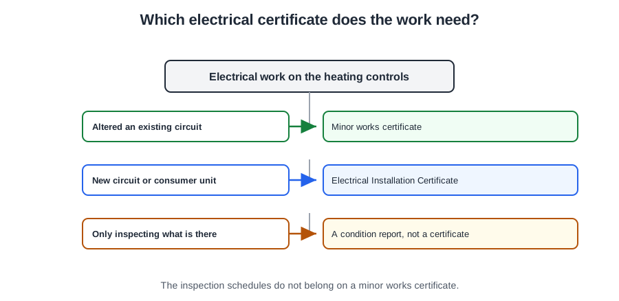
You have extended a kitchen circuit to a new fused connection unit for a boiler. No new circuit, consumer unit untouched. The customer asks for "the certificate". Which one, and does anybody outside the house need to know?
| Document | Used for |
|---|---|
| Electrical Installation Certificate (EIC) | A new installation, or an addition or alteration that includes a new circuit or a new consumer unit |
| Minor Electrical Installation Works Certificate (MEIWC) | An addition or alteration to an existing circuit not extending to a new circuit |
| Electrical Installation Condition Report (EICR) | Periodic inspection and testing of an existing installation |
Regulation 644.4.201: where the work does not include a new circuit or the replacement of a distribution board or consumer unit, a MEIWC may be provided for each circuit added to or altered. So extending a circuit to a new fused connection unit gets a MEIWC. So does adding a spur socket to a ring, or extending a lighting circuit to a new light point. A straight like-for-like swap of a damaged socket is a repair, not an addition or alteration. A condition report is never the right answer for new work — it reports on an existing installation.
The MEIWC carries a description of the works, any departures, comments on the existing installation, the earthing arrangement (TN-S, TN-C-S or TT), the presence of the earthing conductor and main bonding, the circuit details, the test results including R1+R2, insulation resistance, polarity and Zs, and a signed declaration.
What it does not carry is an inspection schedule. Appendix 6 says schedules of inspection and test results are issued with the associated EIC or EICR. That is the standard trap: everything on the list is on a minor works certificate except the inspection schedules.
Notification is a different thing
Certification tells the customer. Notification means telling building control. Only three kinds of electrical work are notifiable:
- The installation of a new circuit.
- The replacement of a consumer unit.
- Any addition or alteration to existing circuits in a special location.
All other work is not notifiable, including additions and alterations outside special locations, and replacements, repairs and maintenance anywhere.
A special location is the space around a bath or shower — up to 2.25 m above finished floor level and 0.6 m horizontally from the edge of the tub or tray — or a room containing a swimming pool or sauna heater. A kitchen is not a special location. So a fused spur off a kitchen ring to feed a boiler is not notifiable — though it still has to comply with Part P and still has to be inspected and tested to BS 7671.
Earthing and bonding
You lift the lid on a circulating pump and find the green-and-yellow core cut off short and pushed to one side. The pump runs. The customer has had heating all winter.
What you have is a Class I appliance with no protective conductor, and the correct course of action is to isolate the pump safely and leave it off until it is repaired.
Class I equipment relies on its metal casing being connected to earth: if a live conductor touches the casing, current flows down the protective conductor, the fault current is large, and the protective device disconnects in a fraction of a second. Remove the protective conductor and none of that happens — the casing simply sits at mains potential waiting for a hand.
The wrong answers are the tempting ones. Connecting the earth terminal to the nearest copper pipe is not earthing: pipework is an extraneous-conductive-part that is bonded, not a protective conductor. Running the pump on a lower speed changes nothing. And a 3 A fuse does not compensate, because a fuse protects the circuit against overcurrent, not a person against a casing at 230 V.
Three conductors, three jobs
- The circuit protective conductor (cpc) runs with the circuit and connects the exposed metalwork of the equipment back to the main earthing terminal. In flat twin-and-cpc cable it is the bare conductor between the line and neutral cores.
- The earthing conductor connects the main earthing terminal to the means of earthing — on TN-C-S, the earthing terminal at the distributor's cut-out.
- The main protective bonding conductors connect the main earthing terminal to the incoming metallic services, so everything a person can touch sits at the same potential.
| Conductor | Size on 25 mm² tails, TN-C-S | Source |
|---|---|---|
| Earthing conductor | 16 mm² | Table 54.7 |
| Main protective bonding to water and gas | 10 mm² | Table 54.8 |
Where the line conductor is over 16 mm² and up to 35 mm², the protective conductor is 16 mm²; under PME it must also be no smaller than the main bonding size, which for a PEN conductor of 35 mm² or less is 10 mm². Sixteen satisfies both. Do not confuse the two: the 16 mm² runs from the cut-out to the main earthing terminal; the 10 mm² are the separate bonds from that terminal to the services.
Regulation 544.1.2 requires the bonding connection to be made as near as practicable to the point of entry, on the consumer's hard metal pipework and before any branch pipework, and where practicable within 600 mm of the meter outlet union. The clamp is to BS 951 and carries the label warning it is a safety connection.
Because 132.16 demands the earthing and bonding be adequate before you alter anything, this is part of the pre-installation check, not an afterthought.
Choosing and routing the cable
A PVC cable has three parts. The conductor carries the current. The insulation is on the live conductors only, giving basic protection against shock and identifying each core by colour. The outer sheath holds the cores together and provides mechanical protection — that, and not insulation, fire resistance or an earth path, is what the sheath is for.
Conductors up to and including 2.5 mm² are usually solid copper. Flexible cable uses many fine strands so it survives repeated bending, which is why motorised valves and pumps arrive with flex.
| Use of the circuit | Minimum copper csa |
|---|---|
| Power circuits | 1.5 mm² |
| Lighting circuits | 1.0 mm² |
| Signalling and control circuits | 0.5 mm² |
The supply from the fused connection unit to the wiring centre carries the boiler and pump, so it is a power circuit and the minimum is 1.5 mm². That is a floor, not a recommendation — current-carrying capacity, installation method and voltage drop may push you higher. The 0.5 mm² figure belongs to signalling and control circuits, not to the pump supply.
Regulation 522.2.1 requires a wiring system to be protected from external heat, and its note names hot water systems specifically. It gives four methods: shielding; placing sufficiently far from the source; selecting a system with due regard for the additional temperature rise; or local reinforcement or substitution of the insulating material.
Notice what it does not give: a distance in millimetres. There is no rule that says 300 mm from a heating pipe. You choose one of the four methods and you can justify it — in an airing cupboard, usually routing clear of the primary flow, sleeving where it must pass close, or using heat-resisting flex.
Regulation 521.10.202 requires wiring to be supported so it is not liable to premature collapse in the event of fire. Note 3 precludes non-metallic clips or cable ties as the sole means of support; Note 4 gives the answer: suitably spaced steel or copper clips, saddles or ties. So plastic clips are not banned outright — they simply cannot be the only thing holding the cable up.
Regulation 514.3.2 requires every core to be identifiable at its terminations: brown line, blue neutral, green-and-yellow protective. Because the cpc in flat twin-and-cpc is bare, it must be sleeved at every termination — including inside a wiring centre. Being enclosed is not an exemption.
Terminations and joints
A replacement pump arrives with a flex too short to reach the wiring centre. The temptation is a connector block dropped behind the cylinder, or a twist and some tape.
Regulation 526.5 requires every termination and joint in a live conductor to be made within a suitable accessory to the appropriate product standard, an equipment enclosure to the appropriate product standard, or an enclosure partially formed or completed with non-combustible building material. Regulation 526.1 adds durable electrical continuity and adequate mechanical strength; 526.7 requires the enclosure itself to give adequate mechanical protection.
Between them they rule out the twisted-and-taped joint, the soldered joint in heat-shrink, and the loose connector block lying in the cupboard — the last fails because it is not in an enclosure at all, however easy it is to reach.
The right answer is a proper junction box or accessory. A junction box is not used to supply equipment straight off a main circuit, but it is perfectly correct for extending control wiring where the circuit already has adequate fuse protection from a fused connection unit.
Fine-stranded conductors
Flex behaves badly in a screw terminal: the strands splay out from under the screw, only some are clamped, and the connection heats up. Regulation 526.9.1 requires suitable terminals, or the conductor ends suitably treated, to avoid separation or spreading of the individual wires.
Regulation 526.9.2 then says soldering (tinning) of the whole conductor end is not permitted if screw terminals are used. Solder creeps under pressure, so a tinned end that felt tight on Monday is loose by Friday. The proper treatment is a ferrule — a small metal tube crimped onto the strands.
Cutting strands away to make the conductor fit is never acceptable: it reduces the cross-sectional area. Different conductor types should not share a terminal either — the screw may clamp only the solid one and leave the fine strands loose; where it cannot be avoided, ferrule the flexible conductor first. Copper and aluminium never share a terminal, because of the electrolytic reaction between them.
The common screw terminals are square, circular, moving-plate, insulation-displacement and pillar. A standard fused connection unit uses pillar terminals for the supply cable. Square terminals, as in socket outlet face-plates, accept up to three conductors, so a single small conductor should be doubled over to give the screw something to bite on. Circular bottom terminals, in light switches and on neutral and earth bars, position the conductor directly under the screw and need no doubling.
Workmanship that gets it right first time: strip the sheath back to leave only 10 to 15 mm inside the accessory; sleeve the bare cpc before it goes near a terminal; leave a little slack so the connection carries no mechanical strain; check no bare conductor shows outside the terminal and no insulation is trapped inside it; and tug each core gently once the screw is tight.
🔢 The numbers worth memorising
- Fused connection unit
- BS 1363-4, accepts up to 13 A
- Heating controls fuse
- 3 A
- Pre-installation check
- Regulation 132.16 — rating, condition, earthing and bonding
- Buried cable
- less than 50 mm deep must be in a prescribed zone, with RCD protection
- Prescribed zone
- within 150 mm of the top of a wall or a corner, or straight to the accessory
- Altered circuit
- Minor works certificate; new circuit or consumer unit, an EIC
- Not on a MEIWC
- the inspection schedules
- Notifiable work
- new circuit, consumer unit, or a special location
- Special location
- 2.25 m above floor, 0.6 m horizontally from a bath or shower
- Earthing conductor, 25 mm² tails
- 16 mm² (Table 54.7)
- Main bonding
- 10 mm² (Table 54.8), within 600 mm of the meter
- Minimum conductor
- power 1.5 mm², lighting 1.0, signalling 0.5
- Heat protection
- one of four methods in 522.2.1 — no fixed distance
- Cable support
- steel or copper clips or saddles; plastic alone is not enough
- Sheath left inside an accessory
- 10 to 15 mm
⚠️ Where people go wrong
- Fitting a 13 A fuse because the accessory takes one. Heating controls are fused at 3 A.
- Connecting a boiler or pump through a plug and socket.
- Leaving an isolator unlabelled. Somebody will switch off what they cannot identify.
- Answering “rating” by counting spare ways. It is maximum demand with diversity.
- Certifying a circuit with scorched terminals without finding the cause.
- Connecting to a cable chased diagonally across a wall.
- Issuing a condition report for new work.
- Expecting inspection schedules on a minor works certificate.
- Notifying a kitchen spur. A kitchen is not a special location.
- Earthing a pump casing to a copper pipe. Pipework is bonded, not a cpc.
- Confusing the 16 mm² earthing conductor with the 10 mm² main bonds.
- Looking for a fixed distance from a hot pipe. There is none — pick one of the four methods.
- Supporting a cable on plastic clips alone.
- Leaving the bare cpc unsleeved inside a wiring centre.
- Leaving a connector block loose in a cupboard. It is not an enclosure.
- Tinning a fine-stranded end for a screw terminal. Use a ferrule.
- Cutting strands away to make a conductor fit.
📝 10-Question Self-Test
Straight from the Level 3 course question bank. Click an option to see whether you got it right — the explanation appears instantly, and there is nothing to submit.
Main protective bonding to the incoming services must be at least half the earthing conductor and never less than 6 mm2 (BS 7671 544.1.1); where the supply is PME, Table 54.8 requires 10 mm2 for a supply neutral of 35 mm2 or less, which is the normal domestic case.
Work out the maximum demand of the installation with diversity applied — the recognition that not everything in a house runs flat out at once. BS 7671 Section 311 requires maximum demand and diversity to be assessed. Counting spare ways in the consumer unit tells you where a breaker will physically fit, not whether the supply and the tails can carry the extra load.
A fused spur supplying a boiler is electrical work in a dwelling, covered by Approved Document P. It is an addition to an existing circuit rather than a new one, so it is certified with a minor electrical installation works certificate, and the customer keeps a copy. A periodic inspection report is tempting, but that reports on the condition of an existing installation, not on new work.
A Class I pump without its protective conductor is a shock risk; it is isolated and left off until the earth is correctly connected.
A supplementary bonding conductor between two extraneous-conductive-parts must be at least 2.5 mm2 where sheathed or mechanically protected, or 4 mm2 if unprotected.
Mechanical protection. The sheath holds the cores together and takes the knocks, the pulling through joists and the abrasion. It is not insulation: that is the coloured covering on the live conductors only, which is why the cpc in flat twin-and-cpc cable arrives bare and has to be sleeved. The sheath is not a fire barrier and it carries no current at all.
Isolate at the origin of the circuit, the consumer unit, and lock it off with an approved device, keeping the key on you, with a warning notice fitted. Pulling the fuse out of the spur secures only what is below that fuse and leaves the spur's own supply terminals live. Removing a fuse and keeping it in your pocket is a recognised way of securing an isolation, but only the fuse you took out at the point of isolation. Taping the spur switch off fails as well, because tape peels.
3 A. The fuse protects the flex and the equipment beyond it, and a programmer, two thermostats, a couple of valve motors and the boiler control board add up to only a few tens of watts. A 13 A fuse in the same carrier would let a faulty valve motor pull more than four times that current before it blew, cooking the flex first. Where the boiler instructions state a rating, fit that one.
Regulation 132.16 states that no addition or alteration shall be made to an existing installation unless it has been ascertained that the rating and condition of the existing equipment (including the distributor's) will be adequate, and that the earthing and bonding arrangements are adequate for the protective measure applied. That is the basis of the pre-installation check at a fused spur: certification, rating and condition. There is no age limit on the accessory and no bar on TT supplies.
Inspection schedules do not appear on a minor works certificate. The form is a single sheet for one addition or alteration to one existing circuit, so it carries a description of the work, the earthing arrangement, the test results including earth fault loop impedance, and the declaration by whoever did it. Schedules of inspections belong with an Electrical Installation Certificate, where a whole installation or a new circuit is being certified.
Going further: the lessons behind this article
This article is the public answer. Unit 333 of the Level 3 course takes the same ground to the depth the exam and the synoptic assignment ask for, in 6 lessons:
- Fused connection units: the accessory that feeds the controls
- Checking the existing circuit: rating, condition and damage
- Certification and notification for heating control work
- Earthing and bonding a heating control circuit
- Choosing and routing cable for heating controls
- Terminations and joints: making the connection last
- Central heating systems: the Unit 333 guide — every article on this unit in one place
- All PlumbMate articles — Level 1, 2 and 3
- The Level 3 course — the whole 8202-35 Diploma