A customer wants the new boiler in the cupboard under the stairs. It will fit. The manufacturer’s instructions ask for 200 mm clear in front and a flue route the cupboard cannot give.
The short answer
The job is not about whether the box fits. It is about what the paperwork demands — and there is a fixed order to that.
Boilers are positioned in accordance with the manufacturer's installation instructions. For a gas appliance that is not advice: it is how you stay compliant with the Gas Safety (Installation and Use) Regulations 1998.
Then: where the instructions are more demanding than a standard, follow the instructions. Where they conflict with statute, statute wins. An instruction cannot authorise you to break a regulation. If you meet a genuine conflict, stop and query it with the manufacturer's technical line before you install.
The boiler and the cylinder
The instructions set the clearances at front, sides, top and bottom, the permitted flue lengths and terminal positions, the condensate route and its fall, and whether the appliance may go in a bedroom or bathroom at all.
Two other documents sit alongside them. Approved Document J governs the flue, the air supply and the hearth. Where the primary heats stored hot water, Approved Document G applies to the storage vessel. Read all three before you mark the wall.
Then think about the person who services it. BS EN 12828 expects a heating system to be designed so it can be serviced and maintained, including filling, draining down and venting. A boiler you cannot reach the case fixings on is a boiler nobody will maintain properly.
For a vented cylinder the position is usually decided for you by the airing cupboard, because the vessel must sit below the feed and expansion cistern and take its cold feed by gravity.
An unvented cylinder is different. Fed at mains pressure, it can go almost anywhere — a utility room, a loft, a plant cupboard. The one real constraint is access to the outside for the D2 discharge pipework. If you cannot get D2 out, the position is wrong however good it looks.
Leave room on every cylinder for the immersion heater to be withdrawn, for the thermostat pocket, and for the controls you have to reach at commissioning. A cylinder squeezed so tightly into a cupboard that the primary flow and return cannot be insulated for the first metre is a cylinder that will never meet Approved Document L, however good the vessel is.
On a new build, agree the positions of the boiler, cylinder, room thermostats and wiring centre with the customer or architect at first fix, and mark them on site. It costs nothing then. Once the plasterer has been, moving a wiring centre is a day's work.
The circulating pump
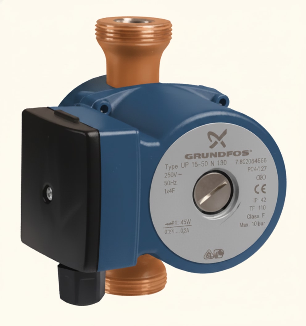
A pump in six weeks is noisy and the system keeps needing venting. Nothing is leaking. It is on a horizontal pipe with the motor hanging underneath it.
A circulating pump performs best in a vertical pipe with the flow pumped downwards. Air rises against the flow and away from the impeller instead of collecting in the pump head, and the shaft stays properly wetted.
If a horizontal position is unavoidable, the motor and shaft must be horizontal — never with the motor hanging below the pipe, where the bearing runs dry and the head fills with air. On a sealed system the pump should, wherever possible, be on the flow pipe. In most modern installations you will not choose at all, because system and combination boilers carry the pump inside the casing.
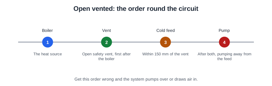
On an open vented system, work away from the boiler in the order vent, cold feed, pump, with the vent and cold feed no more than 150 mm apart. Get it wrong and the system either pumps over the vent or sucks air down the cold feed — both aerate the water and corrode it.
On a sealed system the same idea appears as the neutral point. BS EN 12828 Annex D: the position of the expansion vessel sets it. Choose it so the pressure on the suction side of the pump is high enough to avoid cavitation, and put the fill point between the vessel connection and the pump inlet.
Making the connections
A circulating pump must have isolating valves on both sides. That is the whole reason a pump can be swapped in twenty minutes: close both valves and only the water in the pump body comes out. Without them the system has to be drained, refilled, vented and re-dosed with inhibitor.
The pump connects with flanged unions, and the joint is made with flat rubber washers. Nothing else — not PTFE tape wound round the flange, not fibre washers and jointing paste, not hemp and compound. The washer comes with the pump and the valve set; keep it clean, seat it square, and tighten by hand then a short pull with a spanner.
Check three more things as you fit it. The arrow on the pump body points in the direction of flow. The terminal box faces where a cable can reach it and where water from a weeping union cannot run in. And there is room to get a spanner on both unions without dismantling anything else.
At first fill the pump is normally removed and a temporary section of pipe fitted in its place, so flux, swarf and jointing debris do not pass through the impeller. It goes back in for the flush at operating temperature and for balancing.
Motorised valves, isolation and the bypass
A boiler keeps locking out on overheat about a minute after the room thermostat is satisfied. The wiring is right. The zone valves close as they should. What is missing is anywhere for the water to go while the pump runs on.
Where the motorised valves go depends on the layout: S-plan, one two-port valve per circuit; S-plan plus, a third for a second heating zone; Y-plan, a single three-port mid-position valve; W-plan, a three-port diverter, which cannot hold a mid position.
Wherever they go, motorised valves are fitted in an accessible place, usually the airing cupboard, for three practical reasons: the actuator head has to be removable without cutting pipe; the manual lever has to be reachable, because every motorised valve is manually opened during filling; and the valve body is a common fault point somebody will one day want to see.
Fit the valve head upright or as the instructions allow, never head-down, so a weeping spindle cannot run into the motor.
Isolation valves are placed where they save a drain-down. Two positions matter on every system: at the fill point, and either side of the pump. Add them to each radiator tail, to the cold feed to a cylinder, and to the flow and return of any manifold. On a sealed system the two valves in the filling loop are isolating valves too.
The automatic bypass
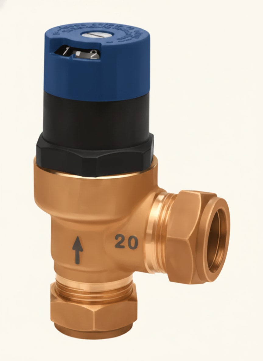
The automatic bypass valve connects the flow pipe to the return pipe, taken immediately after the pump.
It is a pressure-operated valve. As the circuits close — motorised valves shut, TRVs close as rooms reach temperature — the pump pressure rises and the bypass opens automatically, letting water keep circulating through the boiler. It is designed to open when all the TRVs are closed and the hot water circuit is satisfied.
Why it matters: a boiler with a pump overrun circuit keeps the pump running after the burner shuts down, to carry away the latent heat still in the heat exchanger and casing. With no route for that water, the boiler overheats and the high-limit thermostat trips it. So any boiler with pump overrun requires an automatic bypass. Most modern system and combination boilers have the bypass built in, in which case do not fit a second one unless the instructions say so.
Two rules to keep. Set the bypass to the minimum flow rate the boiler instructions demand, not by feel. And never leave one radiator without a TRV and call it the bypass unless the boiler instructions specifically allow it — that room then has no local control, which Approved Document L does not want either.
Radiators
A new radiator fitted tight to the skirting under a deep window sill. The room never feels warm even though the emitter is the right size. Nothing is wrong with the design — the radiator cannot do what a radiator mostly does.
Despite the name, a panel radiator gives about 70 per cent of its output by convection. Air is drawn in at the bottom, warmed as it passes over the welded fins on the back, and rises off the top as a warm current. Radiation from the front panel is the remainder.
That is why a radiator wants a clear wall with no obstruction above it. Where a sill or shelf cannot be avoided, leave enough space above for the warm air to escape and circulate. Furniture pushed against the front kills the radiant share as well.
Fixing height and brackets
Manufacturers recommend at least 150 mm from finished floor level to the bottom of the radiator, depending on the skirting height, so air can be drawn up through the fins. Setting out is a two-measurement job:
- Hold the bracket on the radiator and measure from the bottom of the bracket to the bottom of the radiator. This is measurement A, usually about 50 mm.
- Add measurement A to the 150 mm to give the height of the bottom of the brackets above the floor, and mark that line across the two vertical bracket lines with a spirit level.
Brackets usually offer a near and a far setting. Maximising the gap between the radiator and the wall increases convection; the near setting looks tidier. Agree it with the customer.
Fixings must carry the radiator plus the water in it. On masonry, a 7 mm masonry bit with brown plugs and 50 mm no. 10 screws is usual. On timber-studded or plasterboard walls, use proprietary fixings rated for that combined weight, or fix through to a noggin. Hang the radiator, then check with a spirit level that it is level and still 150 mm off the finished floor.
(The same care over fixing heights applies to any wall-hung item: a wall hung wash basin is normally fixed at about 850 mm from finished floor level to the front edge.)
The valves
A panel radiator takes two valves, and they are not interchangeable:
- A wheelhead valve or TRV gives the user or the room control, normally on the flow.
- A lockshield valve is fitted so the system can be balanced. It is set once with a key at commissioning and then covered, so nobody can disturb the flow rate through that emitter.
Connections by abbreviation: BBOE (bottom bottom opposite end) is the usual method; TBOE is used on heat sink radiators with solid fuel and on one-pipe systems; TBSE with some one-pipe systems.
Dress the radiator on the bench — valve tails, air release valve and blanking plug — before you lift it onto the wall. Radiators are made to BS EN 442.
Pipework: clips, expansion and insulation
A first-floor heating drop ticks and knocks every time the boiler fires. The joints are sound and the pipe is well clipped. That is the problem: it is clipped so tightly, and at such short intervals, that a pipe which grows several millimetres has nowhere to go except against the clip.
| Copper tube | Horizontal | Vertical |
|---|---|---|
| 10 mm | 0.8 m | 1.2 m |
| 15 mm | 1.2 m | 1.8 m |
| 22 mm | 1.8 m | 2.4 m |
| 28 mm | 1.8 m | 2.4 m |
| 35 mm | 2.4 m | 3.0 m |
| 42 mm | 2.4 m | 3.0 m |
| 54 mm | 2.7 m | 3.0 m |
Vertical runs take wider spacing than horizontal ones, because the pipe carries its own weight. Low carbon steel is heavier but far stiffer, so spacings are wider again — ½ inch at 1.8 m horizontal and 2.4 m vertical, rising to 3 m and 3.6 m at 2 inch. Plastic heating pipe is the opposite: limp, and clipped much more often, to the manufacturer's figures.
Choose the clip for the job: nail-on and saddle clips for surface copper, brass munsen rings on a backplate or slotted channel where a bank of pipes runs together, and cast steel school board clips for low carbon steel.
Expansion
Plastic heating pipe run above ground expands about 10 mm per metre at 60 °C. On a 6 m run that is 60 mm of movement, which is why plastic is clipped so it can slide, and why the run is given a gentle set or a loop rather than being pinned rigid at both ends.
Buried pipe behaves completely differently. Once a pipe is encased in concrete or screed the expansion is prevented; it shows only as a microscopic reduction in bore, not as movement. So you allow for expansion in the tails and the exposed runs, not in the floor.
Insulation
BS EN 12828 clause 4.8.1 requires that components which do not contribute directly to heat emission are insulated: to minimise heat losses, to avoid surface temperatures high enough to hurt someone, and to avoid frost damage. Radiator supply pipes in the same zone as the radiator are usually left uninsulated, because their loss goes into the room you meant to heat.
The compliance guide sets the minimums:
- Heating primaries are insulated wherever they pass outside the heated living space, or through voids ventilated from unheated spaces.
- Domestic hot water primaries are insulated throughout their length.
- All pipes connected to a hot water storage vessel, including the vent, for at least 1 metre from the cylinder or to where they become concealed.
- Any pipe kept hot by secondary circulation.
Thickness is set by a maximum heat loss per metre, assessed for a horizontal pipe at 60 °C in still air at 15 °C — for example 7.89 W/m for 15 mm and 9.12 W/m for 22 mm. Where pipework in an unheated area also needs frost protection, BS 5422 gives the method.
🔢 The numbers worth memorising
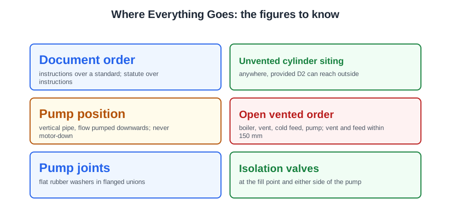
- Document order
- instructions over a standard; statute over instructions
- Unvented cylinder siting
- anywhere, provided D2 can reach outside
- Pump position
- vertical pipe, flow pumped downwards; never motor-down
- Open vented order
- boiler, vent, cold feed, pump; vent and feed within 150 mm
- Pump joints
- flat rubber washers in flanged unions
- Isolation valves
- at the fill point and either side of the pump
- Automatic bypass
- flow to return, taken immediately after the pump, opened by pressure
- Pump overrun
- always requires an automatic bypass
- Radiator output
- about 70 per cent convection
- Radiator height
- at least 150 mm floor to bottom of radiator; measurement A about 50 mm
- Masonry fixings
- 7 mm bit, brown plugs, 50 mm no. 10 screws
- Wall hung basin
- about 850 mm to the front edge
- Copper clips, 15 mm
- 1.2 m horizontal, 1.8 m vertical
- Copper clips, 22 mm
- 1.8 m horizontal, 2.4 m vertical
- Plastic expansion
- about 10 mm per metre at 60 °C above ground
- Insulation loss limits
- 7.89 W/m at 15 mm, 9.12 W/m at 22 mm
⚠️ Where people go wrong
- Fitting a boiler because it physically fits. The clearances and flue route decide.
- Following an instruction that conflicts with a regulation. Statute wins.
- Siting an unvented cylinder without checking the D2 route out.
- Boxing a cylinder in so tightly the first metre of primary cannot be insulated.
- Fitting a pump horizontally with the motor hanging below the pipe.
- Omitting isolating valves either side of the pump.
- Jointing a pump union with PTFE, hemp or fibre washers. Flat rubber, nothing else.
- Leaving the pump in for the first fill. Fit a temporary pipe section.
- Fitting a motorised valve head-down, or somewhere the manual lever cannot be reached.
- Omitting the bypass on a boiler with pump overrun — it trips on overheat a minute after the stat satisfies.
- Setting the bypass by feel instead of to the boiler’s minimum flow rate.
- Leaving one radiator without a TRV as the bypass unless the instructions allow it.
- Fitting a radiator tight under a sill. Seventy per cent of its output is convection.
- Measuring the bracket line at 150 mm. Add measurement A to it.
- Pinning a plastic run rigid at both ends. It grows about 10 mm per metre.
- Allowing for expansion in a buried run. Encased pipe cannot move at all.
📝 10-Question Self-Test
Straight from the Level 3 course question bank. Click an option to see whether you got it right — the explanation appears instantly, and there is nothing to submit.
Pump valves are union connections sealed by a flat washer between the faces; no paste or tape is needed and the washer allows the pump to be removed and refitted.
The lockshield is the valve you balance on. Its shielded head takes a key or a spanner, so once the flow through that radiator is set nobody can knock it or open it up and rob the rest of the circuit. The wheelhead valve at the other end is there for the user to shut the radiator off; if you balanced on that, the setting would last until the first person turned it.
An air separator lets the cold feed and open vent be connected close together on the flow, creating the neutral point so the pump cannot pump over or draw air in.
A pump does best in a vertical pipe with the flow pumped downwards. Air rises against the flow, away from the impeller, instead of collecting in the pump head, and the shaft stays wetted. Where horizontal is unavoidable the motor and shaft must be horizontal — and “the motor hanging below the pipe” is the worst of the lot, because the head fills with air and the bearing runs dry.
Isolating valves, one each side. Close them both and only the water in the pump body comes out, so a pump is changed with a bowl and a cloth in twenty minutes. Without them the whole system is drained, refilled, vented and re-dosed with inhibitor. Air vents and gauges tell you things but neither of them lets you take the pump off.
BS 8204-1 puts a floating sand and cement screed at a minimum of 65 mm above the insulation in a dwelling or under light loads, and 75 mm for heavier loads; BS EN 1264-4 asks for at least 30 mm of screed over the pipe. Thinner than 65 mm, or a flowing calcium sulphate screed, is to the screed maker’s figure. Too thin and it cracks and gives striped output; too thick and the thermal lag becomes unmanageable.
Not enough cover gives striped output and cracking; too much gives a floor that takes hours longer in both directions.
A joisted floor has no screed to spread the heat, so the plate has to do it mechanically.
The same requirement applies to plated and to foil systems alike.
Deduct the joists and the return bend spaces. Active area is usually not less than 80% of gross, but check rather than assume.
Going further: the lessons behind this article
This article is the public answer. Unit 333 of the Level 3 course takes the same ground to the depth the exam and the synoptic assignment ask for, in 5 lessons:
- Boilers and cylinders: siting, access and whose rules win
- The circulating pump: position, isolating valves and unions
- Motorised valves, isolation valves and the automatic bypass
- Radiators: fixing height, brackets and valve connections
- Pipework: clip spacing, expansion and insulation
- Central heating systems: the Unit 333 guide — every article on this unit in one place
- All PlumbMate articles — Level 1, 2 and 3
- The Level 3 course — the whole 8202-35 Diploma