You are about to take the cover off a pump station in an airing cupboard. The programmer says off. The boiler is cold. None of that tells you anything.
The short answer
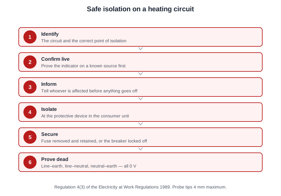
Before a cover comes off, the full procedure is carried out, every time, in the same order:
- Identify the circuit or equipment, and the point of isolation that controls it.
- Confirm the circuit is live before you start — if it already reads dead, find out why, because somebody else may be working on it.
- Inform whoever needs to know, and satisfy yourself it is safe and acceptable to isolate now.
- Isolate at the identified point.
- Secure and label. An approved lock-off device, the key on you, and a warning notice naming the person who applied the isolation and the work being done.
- Prove the voltage indicator on a proving unit or known live supply.
- Test dead at the point of work — then re-prove the indicator.
The Electricity at Work Regulations 1989 sit behind all of it. Regulation 4(3) makes dead working the expectation; live working is only for the rare case where it is unreasonable to work dead, and then only by someone competent, with precautions.
Step 4 is the one that gets dropped
It is also the one that stops somebody switching the supply back on while your hands are in the terminals. It has two halves and both matter.
Locking off is done with an approved device. Where the point of isolation is a circuit breaker or switch, you lock it with a proprietary lock-off device and a padlock. Where it is a fuse that cannot be locked, you remove the fuse and keep it in your pocket, and secure the empty way. You cannot lock off a fuse and you cannot pocket a circuit breaker — so the method follows the device.
On a heating circuit fed from a fused connection unit, the point of isolation is the protective device at the consumer unit. Turning off the spur switch and taping over it is not isolation: the tape comes off, the switch goes on, and the switch was never the point of isolation for the circuit anyway.
Labelling is the half people leave out because a key in a pocket feels like enough. It is not. The tag tells another person on site why the circuit is off, what is being worked on, and who to speak to before restoring it. A key in your pocket says nothing to a colleague standing at the consumer unit wondering why the heating is dead.
What you need before you start: a voltage indicator to GS38, a proving unit compatible with it, a lock or multi-lock system and padlock, warning notices identifying the work, and the right PPE.
Putting it back: all barriers and enclosures go back on first. Then remove the locking device and notice, restore the supply, and check the equipment operates correctly. Reinstating a supply with a cover off, or with a notice still hanging on a breaker somebody else applied, is how the procedure fails at the last step.
Proving dead
Testing dead is the step everybody thinks they can do. It is also the step where a bad habit kills people, because a faulty instrument gives you a confident zero on a live circuit and nothing about the reading looks wrong.
Use a two-pole voltage indicator to GS38, or a proprietary test lamp suitable for the working voltage. GS38 paragraph 19: where a test is simply to establish the presence or absence of voltage, that kind of device should be used rather than a multimeter, because incorrectly set multimeters and makeshift devices have often caused accidents.
Two instruments must never be used to prove dead:
- A neon screwdriver. It relies on current passing through the person holding it, gives no reliable indication that voltage is absent, and can read dead on a live conductor.
- A non-contact voltage stick. GS38 paragraph 13: single-pole or non-contact detectors should only be used for identifying live equipment, not for proving it dead.
A proving unit is not a voltage indicator either. It is the known source you prove the indicator against, before and after.
GS38 on leads and probes: probes should have finger barriers or be shaped to guard against inadvertent hand contact, and be insulated to leave an exposed metal tip not exceeding 4 mm, with 2 mm or less strongly recommended, or spring-loaded retractable screened probes. Long exposed tips are what bridge adjacent terminals and cause an arc flash. Leads used with a multimeter carry a high breaking capacity fuse, usually not exceeding 500 mA.
The three readings
| Test between | Expected | What it catches |
|---|---|---|
| Line and earth | 0 V | Line still connected somewhere |
| Line and neutral | 0 V | The obvious one |
| Neutral and earth | 0 V | A transposed line and neutral, or a voltage on the neutral |
Testing only between line and neutral is the classic short cut, and it misses exactly the circuit you most need to find: one where line and neutral have been swapped, or where a fault has put a voltage on the neutral. That third test is the reason all three are done.
And the re-prove is never dropped, because an indicator can fail between the moment you prove it and the moment you test. If it does, you get zero on a live circuit and no warning at all. GS38 paragraph 20: any device used to prove dead may fail to indicate danger, and such devices should be proved before and after use.
That is the whole logic of the sequence: prove, test, prove. The final step is what makes everything before it trustworthy, and it is the step that turns a reading into evidence.
One more habit worth having: most test lamps will trip an RCD when testing between line and earth, so an approved voltage indicator to GS38 is the better instrument in a domestic consumer unit.
Checking the existing installation
Before any of it is connected, you are joining your work to somebody else's installation, and whatever is wrong with theirs becomes yours the moment you make the connection.
Three questions have to be answered:
- Is the existing installation in good condition?
- Does it have sufficient capacity for what you are adding?
- Does it provide suitable protection for the equipment you are connecting?
None of them is answered by the age of the installation, by whether the consumer unit is metal-clad, or by whether there is a three-phase supply. A ten-year-old installation with a burnt neutral bar fails on condition. A modern board with no spare capacity on the circuit you are spurring from fails on capacity. A circuit with no RCD protection where the cable route requires it fails on protection.
On site: ask for the paperwork — is there a current EIC or condition report, what date, and what did it say? A circuit with recorded defects is a circuit to leave alone until they are put right. Look at the rating: the protective device, the cable size it protects, and the load already on that circuit, then add yours. Look at the condition of the accessory you intend to use. Look at the earthing and bonding. Record what you found — comments on the existing installation are part of the certificate you will issue.
The electrical work itself is governed by BS 7671, the IET Wiring Regulations. Product and scheme standards do not replace it: a manufacturer's installation standard tells you to comply with BS 7671, it does not stand in for it. The legal duty comes from elsewhere — Part P of the Building Regulations makes it a legal requirement that electrical work in a dwelling is carried out so as to protect people from fire and injury. The standard says how; the Building Regulations Part makes it law.
Where the manufacturer's instructions go beyond a standard, you follow the instructions. A standard sets a general baseline; the manufacturer knows the specific appliance — its clearances, minimum system volume, permitted supply arrangement, fuse rating and commissioning sequence. Their instructions set the conditions for correct operation and for the warranty. They do not override the Building Regulations — nothing a manufacturer writes can do that — but where they are more demanding, the more demanding requirement is the one you meet.
Fixed plant needs its own way of being switched off: accessible, adjacent to the unit, and securable in the off position. A lockable switch somewhere else in the property, however well labelled, is not the answer, because nobody working on the unit can see it.
Damaged cable
You pull the room thermostat off its backplate and the cable behind it is discoloured and hard. It has been run against a primary flow pipe in the stud wall, and the insulation cracks when you flex it.
The cable is replaced, and the new one rerouted away from the heat source. That is the only remedy that deals with both halves of the problem: the damage that has already happened, and the cause that is still there.
The tempting alternatives all fail on one half or the other:
- Self-amalgamating tape over the damaged section. Taping is not a permitted way of making good insulation, and the cable is still lying on the pipe.
- A heat-resistant sleeve over the damaged bit. It hides the damage without removing it, and the rest of the run is just as hot.
- Lagging the pipe and leaving the cable. It reduces the heat, but the cable is already degraded and stays degraded.
Where the route cannot avoid the pipe, heat-resisting flexible cable is used instead of ordinary PVC. And replacing rather than patching settles the question you would otherwise be asked later: a cable repaired in place is a cable somebody has to trust without being able to see what is under the tape.
PVC insulation ages fast at temperature. It goes hard, loses its stretch, then cracks when it is disturbed — usually the moment somebody takes a thermostat off a wall. The cable may test perfectly well up to that point, which is why the visual check matters as much as the instrument.
| What you find | Usual cause |
|---|---|
| Flattened or split sheath at a box entry | Fixing screw, or the accessory pulled tight onto the cable |
| Nicks in core insulation | Knife used to strip the sheath |
| Abraded sheath at a metal edge | No grommet in the knockout of a metal enclosure |
| Cable pulled tight with no slack | Strain on the terminations |
| Bare copper showing at a terminal | Too much insulation removed |
| Blackened terminal, brown insulation | Loose connection running hot |
Anything scorched must be put right before certification, and the cause found. A loose terminal or a reduced conductor area gives a high resistance, the high resistance makes the heat, and replacing only the burnt component leaves the cause behind. Usually both the conductor and the component are replaced.
When you install the replacement, fix it properly: metal clips or saddles at suitable intervals (non-metallic clips and ties are not acceptable as the sole support), a grommet where a cable passes through a metal knockout, a little slack at each termination, and protection or depth where the cable crosses a joist or stud.
All of this is looking, feeling and flexing at conductors that must already be dead. The inspection of an existing cable happens after safe isolation, not before, and the cable is proved dead at the point where you intend to disturb it.
🔢 The numbers worth memorising
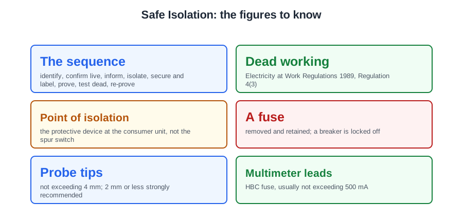
- The sequence
- identify, confirm live, inform, isolate, secure and label, prove, test dead, re-prove
- Dead working
- Electricity at Work Regulations 1989, Regulation 4(3)
- Point of isolation
- the protective device at the consumer unit, not the spur switch
- A fuse
- removed and retained; a breaker is locked off
- Probe tips
- not exceeding 4 mm; 2 mm or less strongly recommended
- Multimeter leads
- HBC fuse, usually not exceeding 500 mA
- The three readings
- line–earth, line–neutral, neutral–earth — all 0 V
- Before connecting
- condition, capacity, protection
- The standard and the law
- BS 7671 says how; Part P makes it law
- Isolation for fixed plant
- accessible, adjacent, securable off
⚠️ Where people go wrong
- Trusting a cold boiler and an off programmer. Neither proves anything.
- Skipping step 4. A lock and a tag — the tag says who and why.
- Taping over the spur switch. That was never the point of isolation.
- Proving dead with a neon screwdriver, a voltage stick or a multimeter.
- Treating the proving unit as the indicator.
- Testing line to neutral only. The neutral–earth reading is the one that catches a transposition.
- Dropping the re-prove. An indicator that failed mid-test reads zero on a live circuit.
- Judging an installation by its age or its consumer unit. It is condition, capacity, protection.
- Taking a manufacturer’s installation standard as a substitute for BS 7671.
- Fitting the isolator somewhere else in the property. It must be adjacent.
- Taping, sleeving or lagging round heat-damaged cable. Replace and reroute.
- Replacing a scorched component without finding the loose connection that cooked it.
- Inspecting an existing cable before isolating it.
📝 10-Question Self-Test
Straight from the Level 3 course question bank. Click an option to see whether you got it right — the explanation appears instantly, and there is nothing to submit.
Proving dead needs a device designed for the job: a two-pole approved voltage indicator to BS EN 61243-3, itself proved on a known supply or a proving unit both before and after the test, as HSE guidance GS38 sets out. A non-contact voltage pen is tempting, but it can read through insulation, miss a live conductor altogether, and cannot be proved.
A capacitor stores charge, and the run capacitor in a pump motor can still be charged after the circuit has been correctly isolated, so the terminals may bite. Prove dead at the pump itself rather than only at the isolator, and allow it time to discharge. Motor windings are tempting, but a winding is just a coil of wire and holds no charge once the supply is off.
Prove the tester, test dead, prove it again — the last step is what catches a failed indicator.
Seven steps: check it is safe and acceptable to isolate and identify the circuit; isolate; secure; label; prove the indicator on a known live source; test dead line-earth, line-neutral and neutral-earth; re-prove. That is the order the City and Guilds book teaches. The IET procedure in Testing of Electrical Installations proves the indicator first and uses it to confirm the circuit is live before isolating, so both orders are met in practice; what GS38 paragraph 20 requires either way is that the indicator is proved before and after use. Securing is a branch rather than a step: lock off a breaker, or remove the fuse and keep it in your pocket.
Lock it off with an approved device and tag it with the name of the person who applied the isolation. The tag is the part people skip, and it is what tells anyone else on site why the circuit is off and who to speak to before restoring it — a key in your pocket says nothing.
All three combinations, all reading zero. Testing only between line and neutral would miss a circuit where the line and neutral had been transposed, or where a fault put a voltage on the neutral — which is exactly the situation the third test exists to find.
A tester that fails between proving and testing gives you a confident zero on a live circuit. Re-proving afterwards is the only thing that closes that gap — which is why the sequence is prove, test, prove, and why the final step is the one never to drop.
Finger barriers, and as little exposed metal as will do the job — 4 mm maximum with 2 mm strongly recommended. Long exposed tips are what bridge adjacent terminals and cause arc flash. Leads should also carry high breaking capacity fuses, typically not exceeding 500 mA, and be coloured to tell them apart.
A neon screwdriver relies on current passing through the user, gives no reliable indication of absence of voltage, and can read dead on a live conductor. A proving unit is not a voltage indicator either — it is the known source you prove the indicator against — but the instrument to rule out here is the neon screwdriver.
Condition, capacity and protection. Connecting new fixed plant to an installation that cannot support it, or that has defects, transfers the problem to you — so the assessment happens before the connection, not after the system fails to start.
Going further: the lessons behind this article
This article is the public answer. Unit 333 of the Level 3 course takes the same ground to the depth the exam and the synoptic assignment ask for, in 4 lessons:
- Safe isolation: the seven steps in order
- Proving dead: the indicator, the proving unit and three readings
- Checking the existing installation before you connect
- Damaged cable: recognising it and putting it right
- Central heating systems: the Unit 333 guide — every article on this unit in one place
- All PlumbMate articles — Level 1, 2 and 3
- The Level 3 course — the whole 8202-35 Diploma