Stand in a cold room in January and the heat is leaving by two doors at once. Some conducts straight out through the fabric. The rest walks out as warm air and is replaced by cold.
The short answer
Heating design keeps those two routes apart from beginning to end, because they behave differently and they are cured differently.
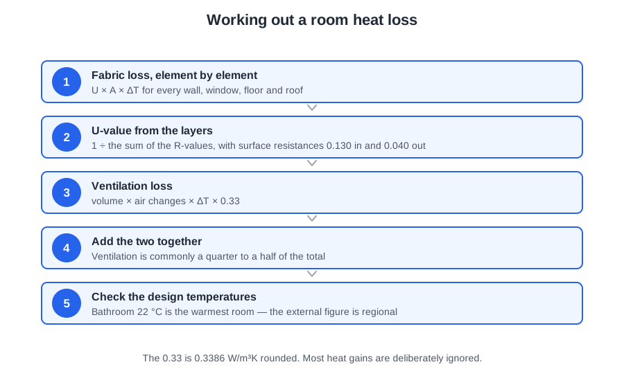
Fabric loss = U × A × ΔT, worked element by element.
Ventilation loss = volume × air changes × ΔT × 0.33.
And one rule decides what goes into the calculation at all: solar and appliance gains are excluded, because the system must hold temperature at night with nothing on.
Fabric loss and the U-value
Heat conducted out through the structure is fabric heat loss, sometimes called transmission heat loss. It is governed by thermal transmittance, the U-value, in W/m²K.
A wall with a U-value of 1.0 W/m²K passes 1 watt through every square metre for every degree of temperature difference across it. So the smaller the U-value, the better the element keeps heat in.
Where a published U-value is not available it can be built up from the materials. Each material has a k-value, its thermal conductivity in W/mK. Divide the thickness in metres by the k-value and you get its R-value, its thermal resistance. Add the R-values of every layer, plus the two fixed air resistances — inside surface 0.130 and outside surface 0.040 — and the U-value is 1 divided by that total.
A brick and block cavity wall with 50 mm of mineral wool and plasterboard totals about 2.848, giving a U-value of about 0.35 W/m²K.
Then it is U × A × ΔT. Never divide by the area and never divide by the temperature difference. And do it element by element, because a window and the wall around it lose heat at very different rates.
Ventilation loss and the 0.33
Air leaks in through gaps, airbricks, ventilators, flues and chimneys, or is pushed in and out by a fan. Warm air escapes, cold air replaces it, and that replacement air has to be heated.
Rate is expressed as the air change rate: the volume of air moving through the room every hour divided by the volume of the room itself. The calculation is room volume × air change rate × temperature difference × 0.33.
The ventilation factor 0.33 W/m³K is not arbitrary. Air at 20 °C has a density of 1.205 kg/m³ and a specific heat capacity of 1.012 kJ/kgK, which is 1.219 kJ per cubic metre per kelvin; convert kilojoules to joules and hours to seconds and you get 0.3386 W/m³K, rounded to 0.33.
Chimneys and flues drive this hard through the stack effect: less dense warm air escapes upward, pulling cold air in lower down. Where mechanical ventilation is fitted, allow for the higher air change rate in connecting rooms too — a bedroom joined to an en-suite with an extract fan.
Keeping the two apart matters because insulation only attacks the fabric half. Ventilation loss is commonly a quarter to a half of the total, and insulation does nothing to it at all. What attacks that half is sealing penetrations and draught-proofing, with heat recovery where mechanical ventilation is used.
Sealing carries its own duty though. Draught-proofing without providing controlled ventilation risks condensation, mould and poor indoor air quality, because moisture and pollutants have to go somewhere. Tightening the fabric and providing ventilation are one job, and whoever sealed the house gets the blame if only half of it is done.
The two design temperatures
The internal design temperature varies with what the room is used for, because comfort depends on what a person is doing in it:
| Room | Design temperature | Air changes per hour |
|---|---|---|
| Lounge, living, dining room | 21 °C | 1.5 |
| Kitchen | 18 °C | 2.0 |
| Hall, landing, cloakroom, toilet | 18 °C | 2.0 |
| Bedroom | 18 °C | 1.0 |
| Bathroom | 22 °C | 2.0 |
| Study, games room | 21 °C | 1.5 |
| Storeroom | 16 °C | 1.0 |
The bathroom is the warmest room at 22 °C, because people are wet and undressed in it. CIBSE Guide A gives comparable ranges — living rooms 22 to 23 °C, bedrooms 17 to 19 °C. Whichever set you use, say on the design sheet which figures you used.
Some designers apply one temperature to the whole house to save calculation. That whole-house approach tends to oversize the system and raise energy use, so it is not the better answer where accuracy matters.
The external design temperature
The outside figure is where people go wrong in the opposite direction. It is a regional figure, typically −1 to −5 °C, taken from published data. It is not zero everywhere, and it is not the coldest temperature ever recorded for the site.
The reason is economic. The UK sees −2 to −6 °C in most winters and has occasionally reached −15 °C, but designing to −15 would oversize every system in the country for a condition that almost never happens — and an oversized generator hunts on its thermostat, cycles and wears out. So the figure used is a realistic low, commonly derived from the lowest two-day mean temperature registered ten times in twenty years.
| Building and exposure | Base design temperature |
|---|---|
| House up to 4th floor, normal or sheltered, England and Wales | −1 °C |
| House up to 4th floor, normal, Scotland, northern England, NI | −3 °C |
| Single-storey house, normal | −3 °C |
| Coastal, high altitude or exposed rural | −4 °C |
| Multi-storey or single-storey, coastal or exposed rural | −5 °C |
Working the difference
The two figures give ΔT. The triangle means change or difference, and t is temperature — not a rate of rise, and not thermal transmittance.
Subtract carefully, because the classic slip is a negative outside temperature. Inside 21 °C, outside −2 °C gives 21 − (−2) = 23 K. Subtracting a negative adds. Answer 19 K or 17 K and you have lost or gained four kelvin across every element of every room.
The result is written in kelvin because it is an interval rather than a position on the scale, and a one degree Celsius interval and a one kelvin interval are the same size.
And the difference is only to the outside where the element faces outside. An internal wall between two rooms at different temperatures has its own smaller ΔT; a wall between two rooms at the same temperature has none.
A room worked end to end
A single-storey extension: 5 m × 3 m × 2.5 m high, all four walls external, floor and flat roof both losing heat. One window 2.0 × 1.5 m, one external door 2.0 × 1.0 m. A study at 21 °C, exposed location, external design temperature −3 °C, 2 air changes per hour. U-values: walls 0.35, floor 0.25, roof 0.25, window and door 2.9.
Temperature difference first: 21 − (−3) = 24 K. That single figure is used for every element.
Step 1 — ventilation. Volume = 5 × 3 × 2.5 = 37.5 m³.
37.5 × 24 × 2 × 0.33 = 594 W
Step 2 — external walls. Laid flat: 5 + 5 + 3 + 3 = 16 m, × 2.5 m high = 40 m². But the openings lose heat far faster than the wall, so they must be deducted before the wall is calculated. Window 3 m², door 2 m², total 5 m². Net wall = 35 m².
35 × 24 × 0.35 = 294 W
Step 3 — glazing and door. Here both share a U-value; check first, because that is not always true.
Window: 3 × 24 × 2.9 = 208.8 W
Door: 2 × 24 × 2.9 = 139.2 W
Step 4 — floor and roof. Both take the plan area, 5 × 3 = 15 m².
Floor: 15 × 24 × 0.25 = 90 W
Roof: 15 × 24 × 0.25 = 90 W
Subtotal: 594 + 294 + 208.8 + 139.2 + 90 + 90 = 1416 W
Step 5 — the adjustments. The room is exposed, so add 10 per cent for severe weather. The heating runs intermittently, so add 15 per cent so the room can be brought back up quickly after an off period.
Exposure: 1416 × 0.10 = 141.6 W
Intermittent: 1416 × 0.15 = 212.4 W
Total: 1770 W
Note the shape of the answer. The ventilation loss alone was 594 W — well over a third of the subtotal. That is normal, and it is why draught-proofing pays.
Doing it for a whole house
Every room gets its own line, in a table with columns for dimensions, volume, air changes, each element's area and U-value, the temperature difference and the watts. Two points catch people out.
First, an internal wall between two rooms at the same temperature still goes on the sheet. List it at 0 K: it adds nothing, but anyone checking can see you looked. Where the rooms differ — a hall at 18 °C beside a lounge at 21 — the internal wall carries its own smaller temperature difference and the watts are real: a loss on the lounge’s sheet, and the same U × A × ΔT as a gain on the hall’s.
Second, the reason for working room by room is that you need two different outputs from the same exercise: the total sizes the heat generator, and the individual rooms size the emitters. Skip the room breakdown and you can still buy a boiler, but you cannot size a single radiator.
Heat gains, and why most are ignored
A south-facing living room with the sun on it, a television, four people and a laptop can be too warm in October and freezing at three in the morning in January. Both are true, and the design has to decide which the system is sized for.
Four sources of gain:
- Solar. Not uniform — the sun rises east, swings south and sets west, so a south-facing wall gains most and a north-facing wall very little. In London a south-facing wall gains roughly 900 W per m² per hour in summer and around 300 W in winter. Warmed outside air adds to this through the sol-air temperature.
- Occupancy. A human at rest emits around 115 W sensible and 50 W latent; activity raises both.
- Electrical equipment and lighting. Anything electrical running indoors turns its power into heat: a 150 W bulb gives off 150 W of heat.
- Adjoining rooms. This is the one the exam asks about. Where one room is at 21 °C and the next at 18, heat crosses the internal wall: a gain to the cooler room and a loss from the warmer. Heat gains from adjoining rooms are allowed for when working out a room's heat requirement, at a rate set by that internal wall's U-value. The same watts go on both sheets, and you only credit a gain from a room the same system holds at its design temperature.
Cold bridges, draughts and unheated roof spaces are losses, not gains.
Solar and appliance gains are excluded from the heat loss calculation because the system must hold temperature at night with nothing on. The design condition is the worst case, not the average: three in the morning, no sun, no cooking, no television, the household asleep and the outside temperature at the design figure. A system sized on a sunny afternoon with the oven on would not hold the house on the night it is needed.
Gains still matter, just not here. They matter for summer overheating, for cooling loads, and for control: a room with heavy solar or appliance gain needs a TRV or a room control that can shut the emitter down, or it will overheat while the rest of the house is still calling for heat.
Pipework heat loss
The pipework is a heat emitter whether you meant it to be or not. An uninsulated 15 mm copper pipe loses around 40 W per metre with water at 75 °C; insulated, about 8 W per metre. Where the pipe runs through a heated room that loss warms the room. Where it runs under a suspended floor, through a roof space or an unheated garage, it is lost entirely.
Two things follow. First, that loss cools the water before it reaches the emitter, so a 5 to 10 per cent allowance is commonly made on the generator size for uninsulated pipework, and a similar percentage is added section by section when pipe sizing.
Second, the compliance guide requires heating primary circulation pipes to be insulated wherever they pass outside the heated space or through voids ventilated from unheated spaces, and hot water primary circulation pipes to be insulated throughout their length. All pipes connected to a hot water storage vessel, including the vent, are insulated for at least 1 metre from the cylinder.
Do not insulate everything indiscriminately, though. Insulating every heating pipe can leave too little temperature difference between flow and return at the boiler, which risks overheating and nuisance operation of the high limit thermostat.
🔢 The numbers worth memorising
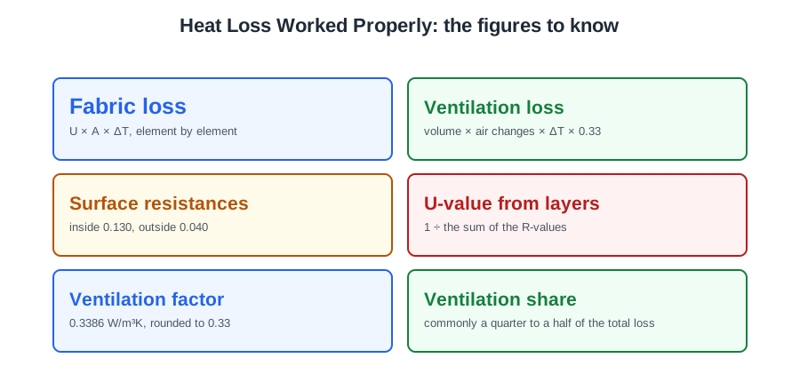
- Fabric loss
- U × A × ΔT, element by element
- Ventilation loss
- volume × air changes × ΔT × 0.33
- Surface resistances
- inside 0.130, outside 0.040
- U-value from layers
- 1 ÷ the sum of the R-values
- Ventilation factor
- 0.3386 W/m³K, rounded to 0.33
- Ventilation share
- commonly a quarter to a half of the total loss
- Bathroom
- 22 °C — the warmest room
- Lounge, study
- 21 °C; kitchen, hall, bedroom 18 °C
- External design temperature
- regional, typically −1 to −5 °C
- Negative outside temperature
- 21 − (−2) = 23 K — subtracting a negative adds
- Exposure allowance
- 10 per cent
- Intermittent heating allowance
- 15 per cent
- Person at rest
- about 115 W sensible, 50 W latent
- South wall solar gain, London
- about 900 W/m² summer, 300 W/m² winter
- 15 mm copper pipe loss
- about 40 W/m bare, 8 W/m insulated
- Pipework allowance
- 5 to 10 per cent on the generator for uninsulated pipe
⚠️ Where people go wrong
- Dividing by the area or the temperature difference. It is U × A × ΔT.
- Working the wall gross. Deduct the window and door areas first — they lose heat far faster.
- Assuming a window and a door share a U-value. Check.
- Answering 19 K for 21 °C inside and −2 outside. Subtracting a negative adds.
- Using zero as the external design temperature everywhere, or the coldest ever recorded.
- Applying one temperature to the whole house. It oversizes the system.
- Leaving an internal wall off the sheet. Between rooms at the same temperature, list it at 0 K; it adds nothing.
- Including solar and appliance gains. The system must hold at three in the morning.
- Calling a cold bridge or a draught a gain. Those are losses.
- Skipping the room-by-room breakdown. Without it you cannot size a single radiator.
- Draught-proofing without providing controlled ventilation.
- Insulating every heating pipe. Too little flow-to-return difference trips the high limit stat.
📝 10-Question Self-Test
Straight from the Level 3 course question bank. Click an option to see whether you got it right — the explanation appears instantly, and there is nothing to submit.
Where the room next door is warmer, heat crosses the internal wall and arrives as a gain, so it comes off the heat requirement of the cooler room. Draughts around windows are tempting, but air leaking through gaps is a loss, not a gain, and so are cold bridges in the structure and heat escaping into an unheated roof space.
Heat loss is fabric loss plus ventilation loss; the air change rate is one of the two inputs.
Friction rises steeply as the bore is reduced, because for the same flow rate the water moves faster and meets more pipe wall for its volume, so resistance goes up and the pump has to develop more head, not less. “Slower flow velocity” is the tempting answer, but a smaller cross-section means a higher velocity for the same litres per second.
Regional, and taken from the data rather than assumed.
The design condition is the worst case, not the average one.
An economic argument as much as a technical one.
Background heating keeps the whole property at a reduced temperature, to take the chill off and protect against frost and condensation, rather than heating it to comfort level.
Designing to a hoped-for future fabric is how a system ends up permanently undersized. Record the measure, and note what the emitter schedule would become.
Moisture and pollutants have to go somewhere. Tightening the fabric and providing ventilation are one job, and the person who sealed the house gets the blame if only half of it is done.
Do the heating first and you have sized and paid for a generator and an emitter schedule for the old fabric — and the generator is then oversized for the improved building, which makes it cycle.
Going further: the lessons behind this article
This article is the public answer. Unit 333 of the Level 3 course takes the same ground to the depth the exam and the synoptic assignment ask for, in 4 lessons:
- Heat loss: the fabric route and the ventilation route
- Design temperatures: inside, outside and the difference
- Working a room: a fabric and ventilation heat loss
- Heat gains, pipework losses and what the design ignores
- Central heating systems: the Unit 333 guide — every article on this unit in one place
- All PlumbMate articles — Level 1, 2 and 3
- The Level 3 course — the whole 8202-35 Diploma