You are asked to move a radiator in a 1960s bungalow. You lift the boards and find one 28 mm pipe running in a big loop, with both radiator tails dropped onto it. There is no separate return — and that changes what you can honestly promise the customer.
The short answer
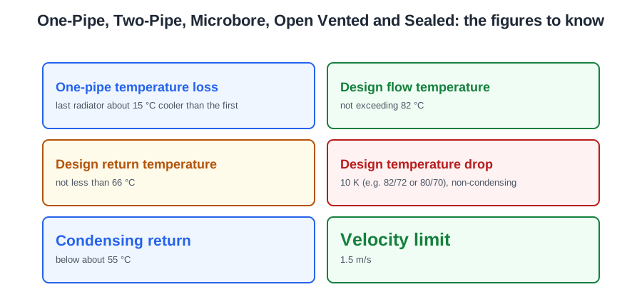
A one-pipe system is a single ring out of the boiler and back. Every radiator tees off it and pushes its cooled water back into the same pipe, so the water gets colder as it goes: on a typical installation the last radiator sees water about 15 °C cooler than the first.
A two-pipe system has a separate flow and return, so every emitter sees water at very nearly the same temperature.
Microbore is not a third kind of system — it is a two-pipe system whose last leg to each radiator is made in very small pipe, fed from a pair of manifolds.
And that is the layout question. The pressure question is separate: open vented takes expansion up into a cistern in the loft; sealed takes it into a diaphragm vessel. A system is one of each — two-pipe and sealed, microbore and open vented, and so on.
One pipe, and why it is a system to replace
Three consequences follow from the single ring, and all three are examinable:
- Each successive emitter has to be larger to compensate for the cooler water reaching it.
- Circulation through each radiator is weak, because most of the water prefers the straight run through the tee to the detour through the emitter.
- Closing radiator valves to balance it does not work — it simply piles resistance onto the whole ring and slows everything down.
BS EN 12828 National Annex NA.4.4.1.1 says all sub-circuits in one-pipe systems should have a valve to regulate the flow through them — that is this problem, written as a rule.
A one-pipe system will not work properly with a combination boiler and cannot meet the current control standards. So a one-pipe layout found on survey is a system to replace, not to extend.
Two pipe, and the design figures
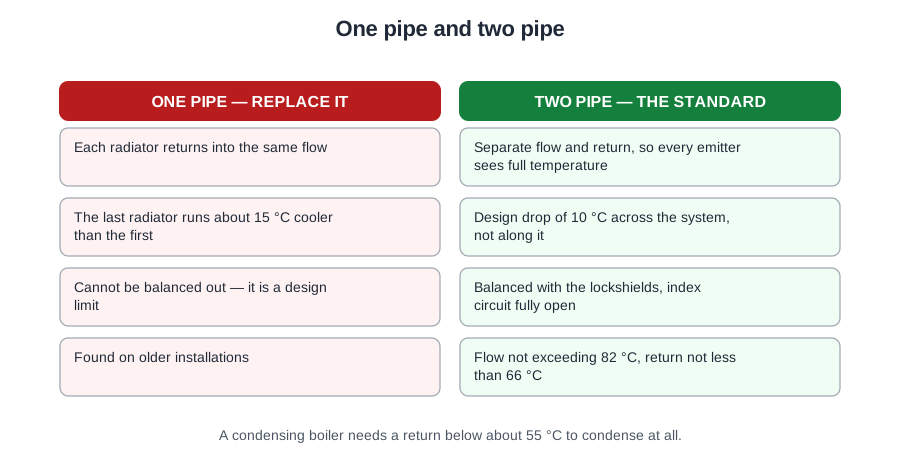
Emitters no longer have to grow along the run, and the system heats up far more quickly because the ring is not being asked to warm each radiator in turn.
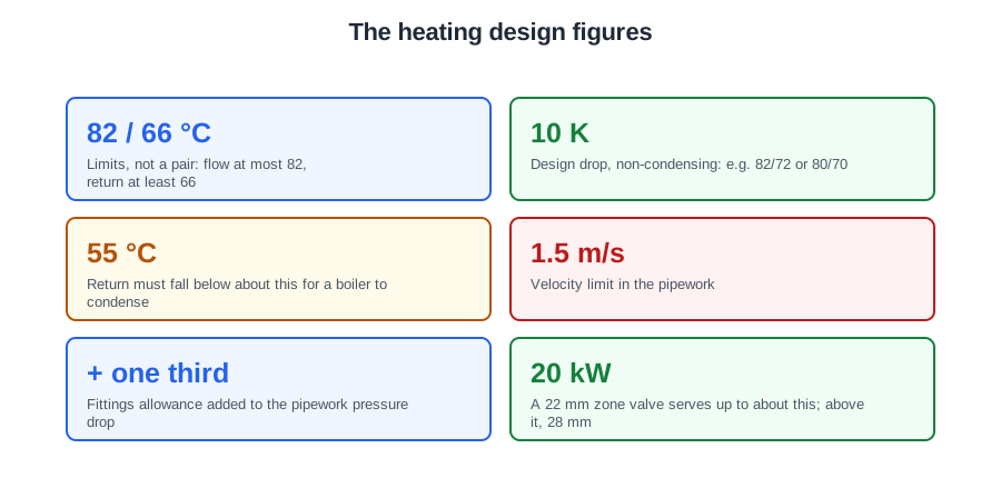
From BS EN 12828 National Annex NA.4.3.3: the design flow temperature should not exceed 82 °C and the design return should be not less than 66 °C, unless the boiler is of special condensing design or the electric storage type. Those two are limits, not a flow and return pair: the system design temperature drop is 10 K for a non-condensing system, for example 82/72 or 80/70.
Older two-pipe systems were commonly designed on a flow of around 80 °C with a drop of 12 to 15 °C, so you will meet both sets of numbers in practice. On a condensing appliance the aim is deliberately the other way: a return water temperature below about 55 °C, because that is what makes the flue gases condense.
Two pipe is also the only sensible arrangement once flow temperatures come down. On a one-pipe loop the mean water temperature falls emitter by emitter — start at 45 °C and there is nothing left to lose.
Reverse return is a variation on two-pipe used on larger installations. The return does not head straight back to the boiler; it sets off in the same direction as the flow and loops round to rejoin the boiler at the far end. The result is that flow plus return length is almost the same for every emitter, so the circuits are close to self-balancing before anyone touches a lockshield.
Whatever the layout, two design limits apply. To keep the system quiet, NA.4.4.1.2 says water velocity should not exceed 1.5 m/s. And when you work out the pressure drop through the pipework, add one-third for the fittings.
One fault worth carrying away. On an unzoned system where the boiler is firing normally, if the upstairs radiators warm and the downstairs ones stay cold, the pump has failed. Hot water is light enough to rise up the flow pipe on its own and reach the upstairs emitters, but nothing is pushing it round the downstairs circuit.
Microbore
A customer complains that one radiator in a 1980s house never gets hot. You trace the tails to a small brass block under the airing cupboard floor with eight tiny copper pipes coming out of it. That block is a manifold.
BS EN 12828 National Annex NA.3.5 defines microbore as circulation pipework normally in the range 6 to 12 mm outside diameter, and smallbore as 15 to 35 mm. In practice the microbore legs are 8 or 10 mm soft copper coil.
The distribution main is conventional: a 22 or 28 mm flow and return run to a pair of manifolds mounted side by side, one on the flow and one on the return. Every flow leg to every radiator comes out of the flow manifold and every return leg goes back into the return manifold. That is the detail that identifies the system in an exam question — a manifold is a feature of a microbore system, while one-pipe and two-pipe systems tee off a main.
The sizing limits
- One pair of manifolds serves up to about eight radiators.
- It is usual to fit a separate pair on each floor; a large property may need two pairs per floor.
- The loop serving the largest radiator should be no more than about 9 m, measured out and back.
Break those rules and the resistance of the small tube swallows the pump head, so the far radiators never get their flow rate. That is usually what is behind a single cold emitter on an otherwise healthy microbore system: an over-long loop, or a leg that has silted up.
The advantages are real: a small volume of water so it heats up quickly, tubing that arrives fully annealed in coils so it bends by hand and threads under floors, and long lengths meaning fewer joints. It can be open vented or sealed, and wired S-plan or Y-plan like any other system.
The disadvantages are equally real. Small-bore soft copper is easily damaged by a knock. And above all it blocks with sludge if the system is not cleaned, dosed and kept clean, because a deposit that would be a nuisance in a 15 mm pipe closes an 8 mm one. On an old microbore system, a power flush and an inhibitor dose are not optional extras.
Two practical points. Microbore radiator legs often go to a twin-entry radiator valve, where flow and return share one tapping through a concentric spigot, so the radiator has one visible connection instead of two. And when balancing, remember the microbore legs already carry a good deal of resistance: the lockshields need far less closing down than on a 15 mm two-pipe system.
Open vented: the neutral point
A householder tells you the loft tank keeps filling with hot water and there is a gurgling noise every time the heating starts. The pump is in the wrong place relative to the vent and the feed — and that single mistake causes most of the classic faults on this kind of system.
The system is fed and vented by a feed and expansion cistern in the roof space. NA.4.7.2.1 says it should be fitted at least 1 m above the highest point of the circulating system, with the boiler manufacturer's instructions giving the minimum head the appliance needs. It is filled through a float-operated valve and left about a third full when cold, so it has room to take the expansion.
Two pipes connect it: the cold feed, typically 15 mm, drops from the cistern and fills the system; the open vent or safety pipe, typically 22 mm, rises from the system and turns over the cistern. That vent is the safety device — if the system ever boils, steam and expanding water have an unrestricted path to atmosphere. No valve of any kind may be fitted in the open vent.
The pump does not just push; it pulls behind it as well. The point where the cold feed and the vent join the system is the one place whose pressure does not change when the pump runs. That is the neutral point.
Get the geometry wrong and one of two faults appears:
- Pump discharging towards the vent → positive pressure there, and water is pumped over the vent into the cistern. The customer sees hot water in the loft tank, and the system takes in fresh oxygenated water every day, which corrodes it.
- Pump drawing from near the vent → negative pressure there, and air is drawn down the vent. Gurgling, cold tops on radiators, and in time more corrosion.
The correct arrangement puts both the cold feed and the open vent on the suction side of the pump, no more than 150 mm apart. That 150 mm limit does two jobs: it makes the suction acting on the two connections nearly equal, and it makes it physically impossible for anyone to fit the pump between the vent and the feed. Alternatively an air separator brings the vent, feed and system connections together in one casting at the right relationship, and takes air out of the water at the same time.
Not every open-vented system is fully pumped. A semi-gravity system pumps the heating circuit but lets the hot water primaries circulate by gravity, using large pipes — typically 28 mm primary flow and return, rising continuously to the cylinder. The drawback is that the cylinder cannot be shut off electrically, the stored water overheats and the boiler cycles. Systems like this are not compliant with current control standards, and the compliance guide lists upgrading gravity-fed systems to fully pumped as good practice when the cylinder or boiler is replaced.
Sealed systems
A boiler is to go in a roof space. There is no room above it for a cistern with the head an open-vented system needs, so the answer is a fully sealed system — and everything else about it follows from the one decision to do without a cistern.
Water expands about 4 per cent between 4 and 100 °C. With no cistern, that expansion is taken in a diaphragm expansion vessel: a steel shell divided by a flexible diaphragm, nitrogen or air on one side, system water on the other.
The vessel goes on the primary return wherever possible, for two reasons. The return water is cooler — typically around 20 °C cooler than the flow — so the diaphragm is not cooked. And the return is the suction side of the pump. If it has to go on the flow, it must still go on the suction side, because the vessel connection is the neutral point of a sealed system: the one place whose pressure stays at the cold fill pressure whether the pump runs or not.
Put the vessel on the pump's discharge side and the pump subtracts its head from the rest of the circuit instead of adding it: pressure on the suction side falls below the fill pressure, air is drawn in at automatic air vents and weeping joints, and the pump inlet cavitates and runs noisily. BS EN 12828 Annex D adds that the filling point should be between the vessel connection and the pump inlet, and that there must be no shut-off valve between the vessel and the heat generator.
Pressures and the safety valve
The vessel is charged before filling. Its charge pressure should be not less than the static head at the centre of the vessel, and it is set to match the intended cold fill pressure, typically 1.0 to 1.5 bar in a house.
The open vent is replaced by a pressure relief valve. NA.4.7.1.1.1 says it should be non-adjustable, spring-loaded and pre-set to lift at a gauge pressure not exceeding 3 bar, have a manual testing device, use seat materials that will not stick shut and reseal properly, and have provision for a full-bore discharge pipe. That pipe must terminate safely: the water leaving it may be well above 80 °C.
Safety valves go close to the heat generator flow pipe, and no isolating valve may be fitted between the boiler and the safety valve. If both the relief valve and the temperature controls fail, the pressure vessel bursts — which is why the relief valve and the manual test lever matter.
Vessel size follows from water content and pressures: National Annex Table NA.2 gives capacities against system volume for safety valve settings of 3.0, 2.5 and 2.0 bar. The acceptance volume of a vessel is what it will take when the pressure has risen to 0.35 bar below the safety valve setting.
The system is filled from the mains through a temporary filling loop with an isolating valve at each end and a double check valve backflow prevention device, connected to the return. The loop is disconnected once the system is full and commissioned. Larger systems use an automatic pressurisation unit.
A rigid pipe system is pressure tested to 1.5 times the working pressure on the traditional convention; BS EN 14336 gives 1.3 times, so both figures are in circulation.
The advantages: less pipework, no cistern in the loft, quicker filling straight from the main, fewer airlocks, and slightly higher operating temperatures, which allows smaller pipes and a wider choice of emitters. A system boiler carries the vessel, pump and safety valve inside its casing; a combination boiler does the same and heats the domestic hot water instantaneously, so it needs no cylinder at all.
🔢 The numbers worth memorising
- One-pipe temperature loss
- last radiator about 15 °C cooler than the first
- Design flow temperature
- not exceeding 82 °C
- Design return temperature
- not less than 66 °C
- Design temperature drop
- 10 K (e.g. 82/72 or 80/70), non-condensing
- Condensing return
- below about 55 °C
- Velocity limit
- 1.5 m/s
- Fittings allowance
- add one third to the pipework pressure drop
- Microbore
- 6 to 12 mm OD; smallbore 15 to 35 mm
- Radiators per manifold pair
- about eight
- Longest microbore loop
- about 9 m out and back
- Feed and expansion cistern
- at least 1 m above the highest point, about a third full cold
- Cold feed and vent
- both on the suction side, no more than 150 mm apart
- Gravity primaries
- typically 28 mm flow and return
- Water expansion
- about 4 per cent, 4 to 100 °C
- Cold fill pressure
- typically 1.0 to 1.5 bar
- Safety valve
- non-adjustable, spring-loaded, not exceeding 3 bar
- Acceptance volume
- at 0.35 bar below the safety valve setting
- Pressure test
- 1.5 × working pressure traditionally; 1.3 × in BS EN 14336
⚠️ Where people go wrong
- Balancing a one-pipe system with the radiator valves. That piles resistance onto the whole ring.
- Quoting to extend a one-pipe system. It cannot meet the current control standards — it is a system to replace.
- Treating microbore as a system in its own right. It is two-pipe with small final legs.
- Balancing microbore lockshields as if they were 15 mm. The small legs already carry the resistance.
- Extending a microbore loop past about 9 m, or a manifold past about eight radiators.
- Fitting any valve in an open vent. It is the safety device.
- Putting the pump between the vent and the feed. Under 150 mm apart on the suction side makes that impossible.
- Diagnosing hot water in the loft tank as a cistern fault. It is pumping over.
- Diagnosing gurgling and cold radiator tops as air in the water. The pump is drawing air down the vent.
- Putting a sealed system’s expansion vessel on the pump’s discharge side. The pump then subtracts its head.
- Fitting an isolating valve between the boiler and the safety valve.
- Leaving the filling loop connected after commissioning.
- Reading upstairs-hot, downstairs-cold as a balancing fault. Gravity reaches upstairs on its own — the pump has failed.
📝 10-Question Self-Test
Straight from the Level 3 course question bank. Click an option to see whether you got it right — the explanation appears instantly, and there is nothing to submit.
A sealed central heating system has no feed and expansion cistern, so the expansion of the water on heating is taken up in a diaphragm expansion vessel. Vented and gravity systems expand into their cistern.
In an S-plan system the cylinder thermostat opens and closes the hot water two-port valve.
In a Y-plan system the auxiliary switch inside the three-port valve is what actually switches the boiler and pump on.
A two-port zone valve is motor-open, spring-return: when the thermostat drops power the spring closes it.
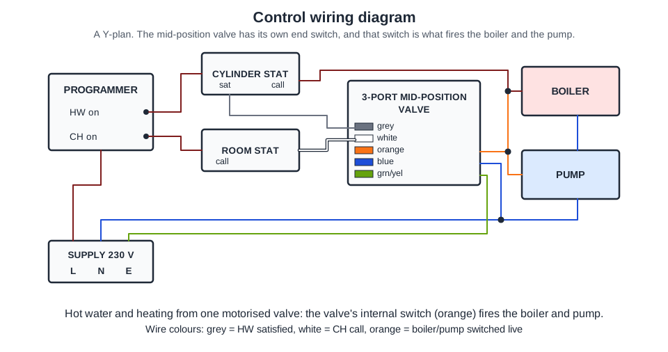
One motorised valve with grey, white and orange wires, fed by both the cylinder thermostat and the room thermostat and switching the boiler and pump from its orange wire, is a three-port mid-position valve: a fully pumped Y-plan system. Two two-port valves would show two valve bodies each with its own switched live.
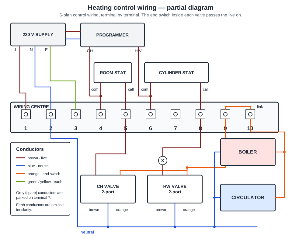
Follow the brown from the hot water valve at X and it lands on terminal 8, the same terminal the cylinder stat call wire comes down to, so the valve is driven open when the cylinder calls for heat. Terminal 5 is the tempting answer, but that is where the room stat call feeds the brown of the central heating valve.
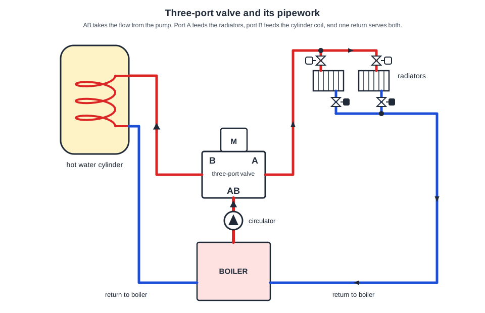
Port B is piped to the coil in the hot water cylinder and back to the boiler, so with A serving the heating, B is the cylinder heat exchanger. The valve is only choosing which circuit the boiler flow is sent to. “Boiler return” is wrong: the returns from the cylinder and the radiators run straight back into the boiler without passing through the valve at all.
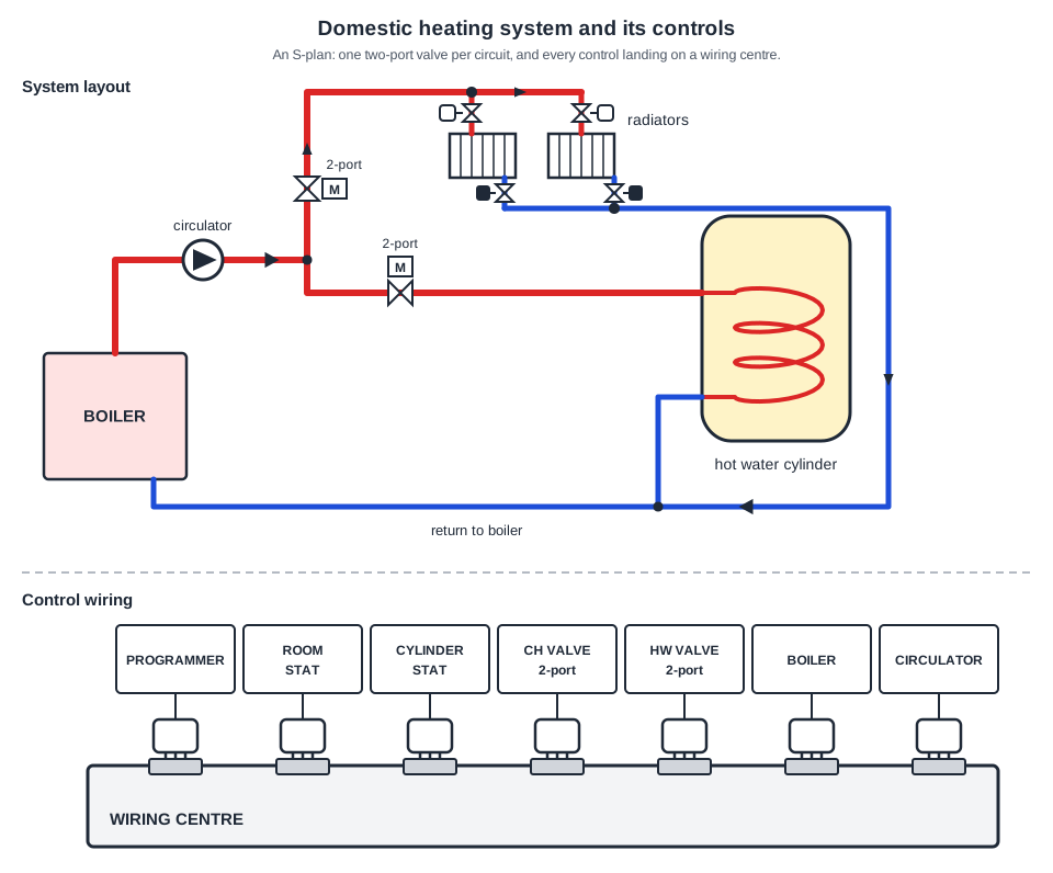
Two separate two-port motorised valves, one on the branch to the radiators and one on the branch to the cylinder coil, both fed from a single circulator: that is S plan. “Y plan” is the tempting answer, but Y plan uses one three-port mid-position valve to split the flow, and there is no such valve anywhere on this drawing.
Boiler interlock is a wiring arrangement, not a component: the boiler is wired so that it can only fire when a room thermostat, cylinder thermostat or programmer is genuinely calling for heat, which stops it cycling just to keep itself hot. Boiler overrun is tempting, but that is the pump running on after the burner shuts down to clear residual heat.
The pipework is S plan, two two-port motorised valves off one circulator. The wiring shown underneath is plug and play: every control and every valve arrives with a pre-terminated lead and a keyed connector that pushes straight into the wiring centre. “S plan hard-wired” would mean stripping the cores and landing them on numbered terminals, which is not what these connectors show.
Going further: the lessons behind this article
This article is the public answer. Unit 333 of the Level 3 course takes the same ground to the depth the exam and the synoptic assignment ask for, in 4 lessons:
- One-pipe, two-pipe and reverse return layouts
- Microbore systems: manifolds, pipe sizes and circuit limits
- Open-vented systems: cistern, vent, feed and the neutral point
- Sealed systems: expansion vessel, filling loop and safety valve
- Central heating systems: the Unit 333 guide — every article on this unit in one place
- All PlumbMate articles — Level 1, 2 and 3
- The Level 3 course — the whole 8202-35 Diploma