Somebody hands you a wiring diagram with two motorised valves, a programmer, a room thermostat and a cylinder thermostat, all landing on a ten-way terminal block. Two valves means S-plan fully pumped — and that identifies the system before you read another line.
The short answer
Count the valves, then count the cores.
- Two two-port valves → S-plan. Three or more → S-plan plus.
- One three-port valve with five cores → Y-plan, a mid-position valve.
- One three-port valve with three cores → W-plan, a diverter.
And on every one of them, the same requirement: boiler interlock — when there is no demand for space heating or hot water, the boiler and the pump are switched off.
S-plan and the five cores
S-plan uses two two-port motorised zone valves: one in the heating circuit, one in the cylinder primary. Each valve is opened by its own thermostat, and each valve tells the boiler and pump when it has opened. Because each circuit has its own valve, each circuit can be controlled and isolated on its own — which is why a fault on one circuit rarely takes the other out with it.
| Core | Function |
|---|---|
| Brown | Live to the valve motor, from the thermostat |
| Blue | Neutral |
| Green-and-yellow | Earth |
| Grey | Permanent live to the auxiliary switch |
| Orange | Switched live out to the boiler and pump |
Inside the valve are a small synchronous motor and a microswitch — the auxiliary switch or end switch. When the thermostat sends live down the brown core, the motor drives the valve open. Only when the valve has reached the fully open position does the microswitch close, passing the permanent live on the grey core out through the orange core to the boiler and pump.
That orange wire is the whole point. On an S-plan diagram you achieve interlock by taking the boiler and pump live from the orange wires of both valves, joined together. If neither thermostat is calling, neither valve opens, neither microswitch closes, and there is no live at the boiler. The boiler cannot fire into a system with no route for the water, and it cannot cycle on its own thermostat while the house is warm.
BS EN 12828's National Annex says the same from the cylinder side: any valve fitted in the primary flow or return of the cylinder for actuation by the cylinder thermostat should be capable of switching to control the boiler and the pump. That is the auxiliary switch, described in a standard rather than on a diagram.
Reading the rest of the diagram: the supply arrives from a switched fused connection unit, 3 A rated. The programmer takes a permanent live and gives two switched outputs. The heating output feeds the room thermostat, whose output drives the heating valve motor; the hot water output feeds the cylinder thermostat, whose output drives the cylinder valve motor. Both orange wires feed the boiler and pump live. The cylinder sensor sits one quarter to one third up the cylinder, normally set to about 60 °C.
Y-plan against W-plan
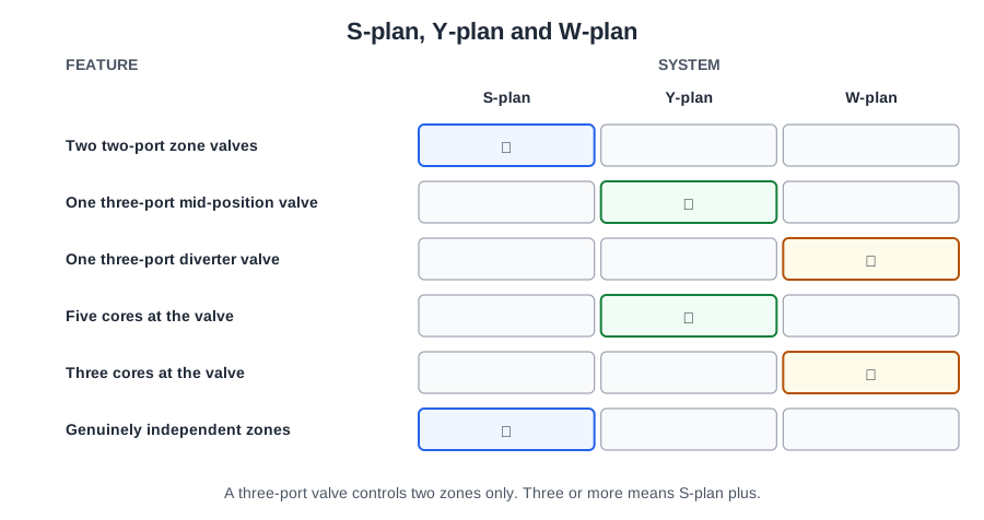
A three-bedroom house where somebody showers while the heating is on. Both valves sit in the common flow, both have three ports, and on a drawing they are almost the same symbol. What separates them is what they can do at once.
- A mid-position valve can sit part way, allowing shared flow to the cylinder and the emitter circuit at the same time. This is Y-plan.
- A diverter valve passes the whole flow to one circuit or the other, never both. This is W-plan, a hot water priority system.
NA.4.6.3.1.2 recommends a mid-position valve where a three-port valve is fitted in the common flow, with a diverter used only if the system design is intended for a priority flow arrangement. So for a house where heating and hot water are often wanted together, the mid-position valve is the answer.
A three-port mixing valve is a different device again: it blends return water into the flow to control circuit temperature, and does not choose which circuit is served. Get those three mixed up on a specification and the system is wrong before a single pipe is cut.
The valve rests in the hot-water-only position with no power on it. From there: hot water only, it stays put; heating only, it is driven hard over to the heating port; both, it is held part way in the mid-position and flow is shared. The boiler and pump live comes out of the valve's own switch, exactly as from the auxiliary switch of a two-port valve.
| S-plan | Y-plan | |
|---|---|---|
| Valves | Two two-port | One three-port mid-position |
| Heating and hot water together | Yes, independently | Yes, sharing one flow |
| Adding a third zone later | Add another valve | Not possible without rework |
| Fault finding | Each circuit on its own valve | One valve serving both |
S-plan plus and multi-zone
A two-storey house, 180 m², one gas boiler and a stored cylinder, with upstairs and downstairs on different times.
Approved Document L (5.14) requires new dwellings of 150 m² or more to have at least two space heating zones, each with an independently controlled heating circuit — and a heating circuit means a pipework run controlled by its own zone valve. Each space heating circuit then needs independent time control plus a room thermostat in a reference room served by that circuit, with TRVs on radiators outside the reference rooms.
So at 180 m²: two space heating zones, each with its own zone valve and its own independent time and temperature control. TRVs alone do not count as a zone — they give room-by-room trimming, not an independently controlled circuit. A single programmable thermostat in the living room does not make two zones either.
Hot water is separate. A stored hot water circuit needs independent time control and electric temperature control — a cylinder thermostat with a zone valve or a three-port valve. Hot water is a circuit in its own right, not a third space heating zone.
NA.4.6.4 sets out what each valve can do: a two-port valve opens or closes a single circuit supplying one zone; a three-port valve controls two zones only; and full independent control can only be achieved by interlocking electrical switching.
So three circuits — upstairs, downstairs and hot water — need a two-port zone valve on each, every valve interlocked electrically to the boiler and pump. That is S-plan plus. A single three-port valve cannot do it: three ports serve two circuits, not three.
The Annex adds a warning for systems using a separate pump per circuit: suitable valves must prevent flow in the other circuits when only one pump is running. Non-return valves do that job.
The wiring is S-plan with an extra leg: each zone gets its own time control, its own room thermostat, its own two-port valve, and its orange switched live joined with the others to the boiler and pump. All three orange wires land on the same terminal. Any one calling brings the boiler and pump on; none calling switches both off — the interlock again.
Two advantages worth stating in an answer: independent control of each zone, so unoccupied parts of the house are not heated; and further zones can be added later with minimal disruption — another valve, another thermostat, another pair of wires into the same wiring centre.
The wiring centre, pump overrun and frost protection
Six cables arrive at the same corner of an airing cupboard. Where they meet decides whether the next engineer can work on this system at all.
A wiring centre is a manufacturer's enclosure with a terminal block whose terminals are printed with what belongs on them. The alternatives are worse: a fused spur is a supply accessory, not a place to gather six cables; a cylinder thermostat has room for the three cores of its own flex and nothing else; and crimped connectors wrapped in insulating tape fail Regulation 526.5 outright.
The programmer is a two-channel time switch: a permanent live in, a heating-on switched live and a hot-water-on switched live out. Those feed the room thermostat and the cylinder thermostat respectively, which drive their valves. The whole lot is fused to 3 A through a double pole switch or fused connection unit.
Pump overrun
Some boilers need the pump to keep running after the burner stops. That is pump overrun, and its purpose is to dissipate residual heat from the heat exchanger so the boiler's energy cut-out does not operate.
The awkward moment is when both circuits are satisfied and both zone valves have shut — there is nowhere for the water to go. So an automatic bypass valve is fitted from the flow just after the pump back to the return, opening when the TRVs are closed and the hot water circuit is satisfied.
On the diagram, a pump overrun boiler is wired with separate terminals marked PL (permanent live) and SL (switched live), plus neutral and earth. The permanent live keeps the boiler's internal overrun circuit alive after the switched live has gone. A boiler wired with only a switched live cannot overrun, because everything dies the instant the valve closes.
Frost protection
A frost thermostat protects pipework in an unheated space. It should always be fitted in conjunction with a pipe thermostat: the frost stat senses air temperature, the pipe stat senses water temperature, and both must be closed before the boiler will fire. That combination stops the boiler firing on a cold night when the water is already hot.
A frost thermostat overrides all other controls — wired to bring the boiler and pump on regardless of the programmer. And it produces one of the classic dangerous faults: a frost thermostat fed from a different circuit means that isolating the heating spur does not make the boiler terminals dead. The whole control system should have one means of isolation; where a rogue supply is found, the frost thermostat is re-installed as part of the controlled system with a single point of isolation.
The dead tests, in order
Every dead test starts from the same place: the circuit is isolated at the consumer unit and locked off with an approved device, and a warning notice fitted. Switching off at the spur and taping over the switch is not isolation — the spur is not the point of isolation, and anyone can peel the tape off.
Regulation 643.1 requires the tests to be carried out in order, before the installation is energised: continuity of conductors, insulation resistance, protection by SELV/PELV or separation, floors and walls, and polarity. For a domestic radial circuit that reduces to three:
- Continuity of protective conductors (and of the live conductors on a ring final circuit).
- Insulation resistance.
- Polarity.
Each test makes the next safe or meaningful. Continuity comes first because a broken protective conductor leaves everything downstream unearthed — you want to know before you apply 500 V to anything. Insulation resistance comes next because it finds a breakdown that would otherwise show up the first time the circuit is energised. Polarity comes last, on a circuit already proved continuous and sound; doing polarity first proves nothing you can rely on.
Regulation 643.1 also says that if any test shows a failure, that test and any preceding test whose result may have been influenced must be repeated once the fault is put right.
Earth fault loop impedance is not in this list. It is a live test under 643.7.3, after energising. So is RCD operation, and so is prospective fault current.
| Dead test | Instrument |
|---|---|
| Continuity of protective conductors | Low-resistance ohmmeter |
| Continuity of ring final circuit conductors | Low-resistance ohmmeter |
| Insulation resistance | Insulation resistance tester |
| Polarity | Low-resistance ohmmeter |
Insulation resistance with electronics connected
Table 64 requires a circuit up to and including 500 V to be tested at 500 V DC, with a minimum insulation resistance of 1 MΩ, and 643.3.2 requires current-using equipment to be disconnected.
A modern heating circuit is full of electronics. Regulation 643.3.3 deals with it: where a circuit includes electronic devices likely to influence the results or be damaged, only a measurement between the live conductors connected together and the earthing arrangement shall be made.
So you either disconnect the electronic equipment, or link line and neutral together and test that pair to earth at 500 V, looking for at least 1 MΩ. What you do not do is test at 1000 V with everything connected, or record the test as not applicable.
Some tests are about one component, not the installation. To assess how the motor in a zone valve is performing, the test is a dead test for resistance: an ohmmeter across its leads should give a reading, and an infinity or OL reading means the winding is open circuit and the motor is finished. Loop impedance testers, RCD testers and prospective fault current testers all measure the supply and the protective arrangements — none of them tells you anything about a valve motor.
Test leads follow HSE guidance GS38: where leads are used with a multimeter they should carry a high breaking capacity fuse, usually not exceeding 500 mA. The fuse is there so a wrongly set instrument, or a probe that slips, cannot deliver the full fault energy into your hands.
What polarity and earth continuity each prove
An engineer tests an existing heating circuit and finds the fuse and the switch of the fused connection unit sitting in the neutral. Everything works. The boiler fires, the programmer clicks. The circuit is also badly dangerous.
The polarity test checks that live and neutral are wired correctly, and a failure means they have been crossed. Regulation 643.6 verifies that every fuse and single-pole control and protective device is connected in the line conductor only, that wiring is correctly connected throughout, and that centre contacts of Edison screw lampholders are on the line conductor.
Put the fuse and the switch in the neutral and the consequence follows immediately: switch off at the spur, or blow the fuse, and the boiler and its controls are still connected to line potential through the neutral path. The system looks off. It is not off. Anyone who opens the boiler case on that basis is working live without knowing it.
An earth continuity test confirms that all appropriate parts are earthed. It does not check polarity, insulation or supply voltage. It answers one question: is there an unbroken, low-resistance path from every piece of exposed metalwork back to the main earthing terminal? Without it, the earth fault loop is broken, the protective device will not disconnect quickly, and the casing of a faulty pump stays live.
The method on a radial circuit
The standard method proves continuity and polarity together and gives you R1+R2. With the circuit isolated:
- At the origin, link the line conductor and the cpc together with a short lead. While doing it, check visually that the line conductor is correctly identified and connected into the protective device.
- At the furthest point — the fused connection unit — remove the accessory and check visually that the line conductor is in the correct terminal.
- Null the leads of the low-resistance ohmmeter, then connect between the incoming line and cpc terminals. A very low reading proves continuity, and that reading is R1+R2.
- Remove the link at the origin and test again. The reading should now be high, which proves you tested the right circuit.
Step 4 is the one people skip, and it is the one that catches a reading taken through a parallel path or a neighbouring circuit.
A main bonding conductor is tested end to end with a low-resistance ohmmeter after safe isolation, with one end disconnected so parallel paths do not flatter the result. Take the reading from the disconnected end to the bonded metalwork rather than to the clamp, so the clamp itself is proved. Subtract the lead resistance unless the instrument has been nulled, and reconnect as soon as the test is finished.
🔢 The numbers worth memorising
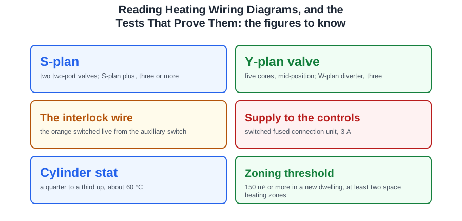
- S-plan
- two two-port valves; S-plan plus, three or more
- Y-plan valve
- five cores, mid-position; W-plan diverter, three
- The interlock wire
- the orange switched live from the auxiliary switch
- Supply to the controls
- switched fused connection unit, 3 A
- Cylinder stat
- a quarter to a third up, about 60 °C
- Zoning threshold
- 150 m² or more in a new dwelling, at least two space heating zones
- Three-port valve limit
- controls two zones only
- Pump overrun boiler
- needs PL and SL terminals and an automatic bypass
- Frost stat
- always with a pipe stat; both must close; one point of isolation
- Dead test order
- continuity, insulation resistance, polarity
- Insulation resistance
- 500 V DC, minimum 1 MΩ
- With electronics connected
- lives linked together, tested to earth only
- GS38 test leads
- fused, usually not exceeding 500 mA
- Radial continuity
- link line to cpc at the origin, read R1+R2, then remove the link
⚠️ Where people go wrong
- Reading a three-port valve as Y-plan without counting the cores. Three cores is a diverter.
- Confusing a mid-position valve with a three-port mixing valve.
- Wiring the boiler live from the programmer instead of the valve auxiliary switches. That is no interlock at all.
- Counting TRVs as a zone, or a living-room programmable stat as two zones.
- Counting hot water as one of the two space heating zones.
- Trying to serve three circuits with one three-port valve.
- Gathering control cables in a fused spur, a cylinder stat, or crimps and tape.
- Wiring a pump overrun boiler with a switched live only.
- Omitting the bypass on a pump overrun system.
- Feeding a frost stat from a separate circuit. Isolating the heating then leaves the boiler live.
- Taping over a spur switch and calling it isolation.
- Doing polarity first. It proves nothing on an unverified circuit.
- Listing earth fault loop impedance or RCD operation as dead tests.
- Testing insulation resistance at 1000 V with electronics connected, or recording it as not applicable.
- Using a loop tester to assess a valve motor. That is a dead resistance test.
- Skipping step 4 and accepting an R1+R2 taken through a parallel path.
- Testing a bonding conductor with both ends connected.
📝 10-Question Self-Test
Straight from the Level 3 course question bank. Click an option to see whether you got it right — the explanation appears instantly, and there is nothing to submit.
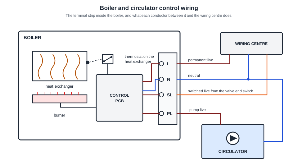
Terminal PL is held live from the permanent live through the thermostat on the heat exchanger, so when the burner shuts down the circulator keeps running until the heat exchanger has cooled. That is pump overrun, and it carries the residual heat away instead of letting it boil in the boiler. “To give frost protection” needs a frost thermostat sensing cold air, and that would fire the burner as well.
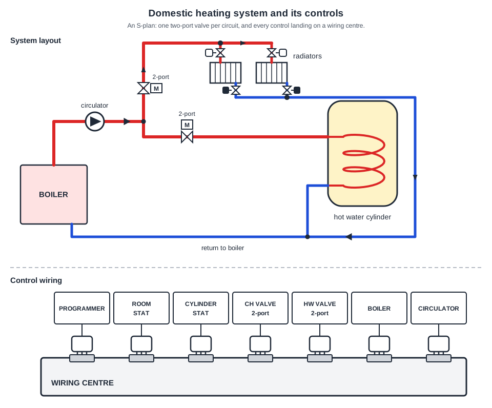
Both circuits are served through their own two-port motorised valve from a single circulator, so the radiators and the cylinder coil are pumped, with nothing left on gravity. That is S plan, fully pumped. “C plan semi-gravity” is the tempting one, but C plan leaves the hot water on a gravity primary with no valve on it, and here both branches are valved.
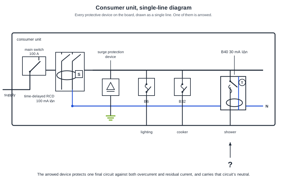
The arrowed device is an RCBO: a circuit breaker and a residual current device in one module, marked B40 30 mA, with its own test button and the shower circuit’s neutral taken through it. BS 7671 Part 2 defines it as a residual current operated circuit-breaker with integral overcurrent protection. “A time-delayed RCD” is the 100 mA S type device next to the main switch, and it gives no overcurrent protection.
Pillar terminals. The conductor goes into a hole drilled through a brass pillar and a grub screw clamps it from the side, which is what you find behind the faceplate of a standard fused connection unit. Screw-down clamp plates are the square terminals used in socket outlets, and crimp lugs on studs belong to larger switchgear, not a 13 A accessory.
Dead tests run in the order continuity of protective conductors (and ring continuity), insulation resistance, then polarity, so that each test is safe to carry out given the results of the one before.
500 mA. HSE guidance GS38 says test leads used with an instrument should carry a high breaking capacity fuse of a suitable rating, usually not exceeding 500 mA. It is there so a wrongly set meter or a probe that slips cannot deliver the full prospective fault energy back down the leads into your hands. A 3 A fuse would let far too much through before clearing.
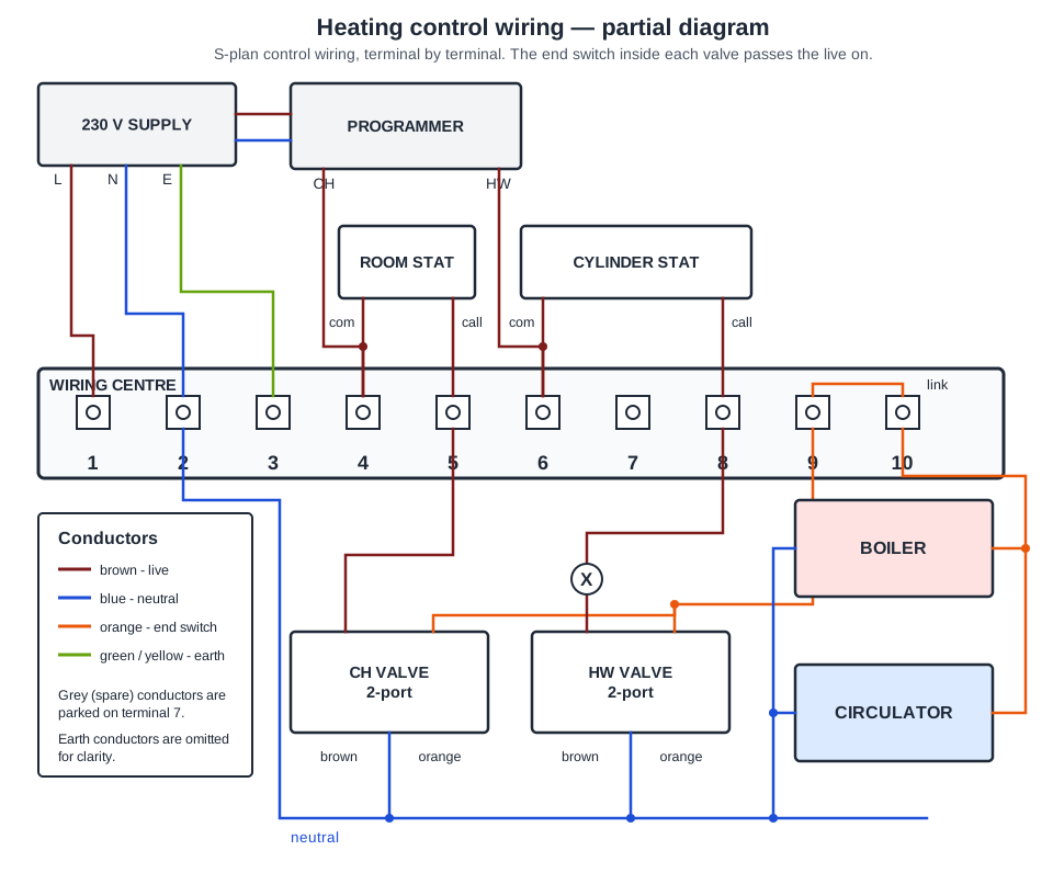
NA.4.6.3.1.2 states that any valve fitted in the primary flow or return of the cylinder for actuation by the cylinder thermostat should be capable of switching to control the boiler (except for solid fuel) and the pump where the system is fully pumped. On the diagram this is the valve's auxiliary switch, which feeds the boiler and pump live once the valve has driven open. The gravity-fallback provision applies to solid fuel systems, not gas.
The commentary to NA.4.6.3.1.2 says that where a three-port valve is fitted in the common flow, a mid-position valve is recommended because it can allow shared flow distribution to the cylinder and heat emitter circuits. A diverter type, which allows circulation to only one circuit at a time, may be used where the design is intended for a priority flow arrangement. A mixing valve controls flow temperature, not which circuit is served.
Approved Document L (Volume 1, 2021, paragraph 5.14) says new dwellings with a floor area of 150 m2 or more should have at least two independently controlled heating circuits, so 180 m2 needs two space heating zones. A heating circuit is a pipework run controlled by its own zone valve (the definition in the Domestic Building Services Compliance Guide, which Approved Document L replaced in June 2022), and each has its own time control and room thermostat. Hot water is a separate circuit with its own time and temperature control (5.16), not a space heating zone.
Table 3 of the Compliance Guide (item 1.0, boiler interlock) requires system controls to be wired so that when there is no demand for space heating or hot water, the boiler and pump are switched off. In an S-plan diagram this is achieved by routing the boiler and pump live through the auxiliary (end) switches of the two-port valves, so neither can run unless a thermostat has called and a valve has opened.
Going further: the lessons behind this article
This article is the public answer. Unit 333 of the Level 3 course takes the same ground to the depth the exam and the synoptic assignment ask for, in 6 lessons:
- S-plan: two-port valves and the boiler interlock
- Y-plan: the mid-position valve and how it differs
- S-plan plus and multi-zone wiring for larger houses
- Wiring centres, programmers, pump overrun and frost protection
- Dead tests and live tests: the order and the instruments
- Polarity and earth continuity: what each test proves
- Central heating systems: the Unit 333 guide — every article on this unit in one place
- All PlumbMate articles — Level 1, 2 and 3
- The Level 3 course — the whole 8202-35 Diploma