Two engineers commission the same heat pump into the same house. One leaves the flow temperature at 55 °C because that is what the old boiler ran at; the other spends an hour on the curve and leaves it at 40.
The short answer
Same equipment, same emitters — and a running cost difference the customer will notice every month for fifteen years. Setting the controls is where the design efficiency is either realised or thrown away.
Three habits carry this whole stage: check the vessel charge with the system depressurised, prove the thermostats one room at a time, and record the measured values and the settings applied, in full.
Operational checks
BS EN 14336 clause 5.8 asks for every component to be checked for correct operation, so that defects are found and put right before setting to work and balancing, not during it.
Start with the check people get wrong. A diaphragm expansion vessel has air on one side and system water on the other. Put a gauge on the schrader valve while the system is full and pressurised, and the reading is the sum of the charge and the water pressure pushing back — not the charge.
So the vessel charge is checked with the system depressurised, and compared against the cold fill pressure. The sensible time to do it is before the system is filled. It is a two minute job then and an awkward one later. Use a portable Bourdon gauge, and take the figures from the manufacturer's instructions.
Then the mechanical checks from Annex D. With the system full: the pump mounted the right way round and up, clean and secure, impeller turning freely, no strain on the connections. On automatic control valves: ports the right way round for the flow, spindles free, mountings rigid, actuators fitted as required with access to their connections. Check the pressure relief valve lifts and reseats. Check the gauges read sensibly — gauges are notorious for reading wrong.
The electrical part of commissioning is not about the heating settings at all. It is about the two things somebody's safety later depends on: verifying the protective device, and confirming that the means of isolation works. With the supply off: circuits locally isolated, no unprotected live parts in the panels, all connections tight, wiring matching the circuit diagram, all fuse ratings correct. With the supply on: correct provision for local isolation, correct voltage present, and contactors, relays and interlocks operating positively.
Prove the controls one room at a time
Set every thermostat down so the system stops, then turn one up, wait, and confirm the right zone valve or actuator opens for that room. Turn it back down, wait for the system to stop, and move on.
Why one at a time? Because two thermostats crossed at the wiring centre behave perfectly normally when you switch everything on together. The boiler fires, the valves open, the house warms up and nothing looks wrong — until the customer finds that turning the bedroom stat up heats the lounge.
Be patient with the valves: a thermal actuator typically takes 2 to 4 minutes to open fully, so allow the travel time before deciding one has not worked.
And when a reading comes back outside the design parameters, the answer is always the same: investigate and rectify the cause, then re-check before completing. You do not note the deviation and move on, you do not leave it for the first service, and you certainly do not adjust the design figure to match what the system achieves.
The two omissions that come back as faults years later are exactly the ones nobody notices on the day: inhibitor never dosed or recorded, and settings never written down.
Setting the controls
Weather compensation varies the flow temperature with the outside temperature. The principle that guides the setting is the lowest flow temperature that still holds comfort — not the highest the emitters are rated for, not a fixed figure so the curve never needs touching, and certainly not whatever the previous boiler was set to.
Every degree you can give back is efficiency you keep, and on a heat pump the effect is large, because the machine works harder for every degree of lift. Set the curve, then leave the system long enough to prove it in real weather, and adjust from the customer's experience rather than from the first afternoon's readings.
Where the system feeds a stored cylinder, two settings must be established: the storage temperature and the pasteurisation cycle.
A heat pump stores at 45 to 52 °C, because a higher store costs efficiency. But stored water below 60 °C is water in which legionella can multiply, and ACOP L8 makes controlling that a duty. So a pasteurisation cycle is scheduled: normally weekly, the whole stored volume is raised to 60 °C. It has to be the whole volume, not just the water round the sensor — and it has to be scheduled, because a cycle nobody has set is a cycle that never runs.
Defrost is the one function you cannot check from the settings screen: it has to be seen. Where conditions allow, verify at commissioning that the cycle starts and stops correctly and the water drains away. Meltwater that cannot drain freezes at the base of the unit, blocks the coil and eventually damages the fan.
Almost all of commissioning is open to you — the compensation curve, the hot water schedule, flow and return temperatures, the vessel charge, balancing, dosing, water testing. The refrigerant circuit is not. Breaking into the sealed circuit and adjusting the charge must not be carried out without an F-Gas qualification. The boundary is easy to remember: everything on the water and control side is open; the sealed circuit is not.
One last rule that applies to every setting: let the system run to stable conditions before commissioning readings are taken, because warm-up figures do not represent steady-state performance. Set, wait, then measure.
Balancing radiators
The far bedroom is cold and the hall radiator is scalding. Nothing is broken. The water is simply taking the easiest path, straight round the short circuits nearest the pump and back to the boiler.
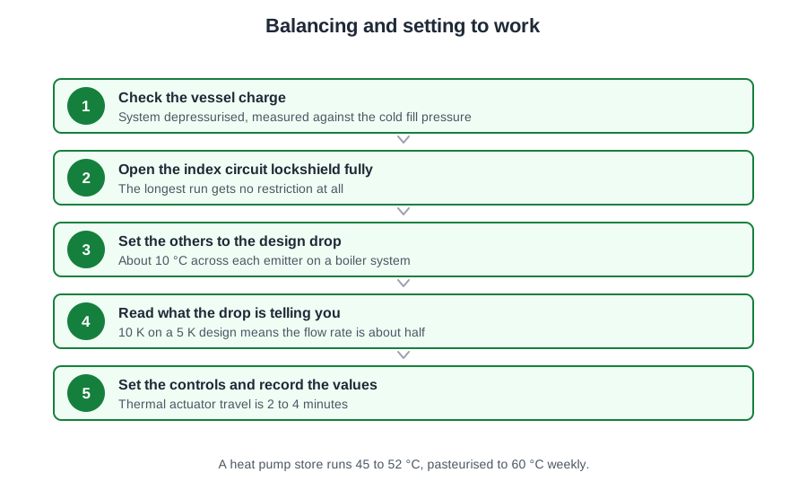
Balancing means setting each circuit so that each emitter gets the flow its designed output needs. It is not about making every return the same temperature, not about letting the pump run on its slowest speed, and not about matching a total flow to the appliance's rated figure. The lockshield is the balancing valve, and zone valves must be open throughout.
For a given output, flow rate and temperature difference are inversely related. Push more water through an emitter and it comes back nearly as hot as it went in, so the difference shrinks; push less through and the difference grows. That makes the temperature difference the flow rate made visible.
So if a system designed for a 5 K difference measures 10 K across the appliance at full output, the flow rate is about half the design figure. The arithmetic runs the other way too: too much flow through an emitter collapses the difference and raises the return — and on a heat pump the return temperature is what the whole efficiency case rests on. Balancing is not only about comfort in the far bedroom.
The lockshield method
On a boiler system with a design difference of about 10 °C:
- Record the existing settings — TRVs, lockshields, stat, boiler, pump speed — so you can get back to where you started.
- Open all zone valves, TRVs and lockshields fully, counting the turns from closed to open. Set the room thermostats to maximum.
- Bleed all radiators cold and check the system pressure.
- Fire the boiler and note which radiators heat first — those are taking too much flow.
- Throttle those lockshields back about halfway, then let the system stabilise for about an hour.
- Read flow and return at every radiator, record them, and work out each difference.
- Close the lockshields a little on the radiators with the smallest difference, recording the turns. Repeat until every radiator is hot and every difference is near 10 °C.
- Set the boiler flow to about 80 °C, then adjust the pump speed until the difference across the boiler is right. Changing the pump speed disturbs the balance, so expect to go round again.
- Set the TRVs and stats to the temperatures the rooms actually need, and record the final boiler flow and return.
The index circuit — the one with the least pressure available, usually the longest run — is the one you cannot help by throttling. Its lockshield is set fully open, and every other circuit is throttled back to match it.
On a 5 K design the method runs out of resolution. Contact and clamp probes are accurate to about ±0.5 K, so on a 5 K difference the measurement error is a fifth of the whole quantity you are setting — exactly where the design has least tolerance to spare. BS EN 14336 Annex G says the temperature balance method suits systems where the permissible flow deviation exceeds ±20 per cent, carried out at a drop of at least 0.75 times the design drop.
The better method at low temperature is to measure flow directly: flow-measuring valves set in litres per minute, or the manufacturer's presetting data giving turns from closed. It is what an underfloor manifold has always done.
And when you replace a pump and discover the system was never balanced: balancing is real work, takes real time and was not in the job you quoted. The right move is to obtain the customer's agreement before balancing the system — not to fudge it with pump speed, not to note it on the paperwork and walk away, and not to blame the pump manufacturer.
Starting up an underfloor manifold
Two chrome bars with a lot of identical brass on them. Get the two bars the wrong way round in your head and balancing becomes impossible.
- The flow bar distributes water. Every loop carries a flow meter — a sight glass with a float, reading in litres per minute. A flow meter shows what a loop is passing and regulates nothing at all.
- The return bar collects the water back. Every loop carries a regulating valve — the manifold's version of a lockshield, set with a key. The actuator for room control sits on top of it.
So: meters indicate; return lockshields regulate. There is no lockshield in the radiator sense because each loop is balanced at the manifold. Actuators only open or close a loop on a call for heat; they do not regulate — confusing an actuator with a regulating valve makes balancing impossible.
One more component matters: the differential valve automatically regulates pressure changes within the manifold. Without it, one adjustment moves all the others and you chase your tail.
With the system filled, vented and every isolating valve open, set the heat source to 82 °C, or a minimum of 15 K higher than the underfloor design flow temperature. The one exception: if the heat source itself is directly controlling the design flow temperature, set it to the starting temperature of the system instead.
You need the technical printout for the project, giving the turns from closed for each lockshield, and a 4 mm Allen key:
- Close every lockshield valve fully. That is the first step, always — you set from a known position, not from wherever the valves happen to be.
- Open each valve the required number of turns, making sure each gets the figure for the loop it actually serves, not the one next to it.
- Replace the washer disc and tighten the brass cap finger tight.
- Check the blending valve is delivering the design temperature, using the dial thermometers, and set the manifold pump to a suitable speed.
Then prove the controls. With the electrical power off, set every room thermostat 5 K above the current room temperature so all are calling, and set the water temperature control to its lowest setting, between 25 and 30 °C. Switch on, confirm the pumps run and the valves open, allowing 2 to 4 minutes for the actuators to travel. Then turn all the thermostats down and wait for the system to stop.
Now the important part: turn one thermostat up, confirm the correct loop actuator has opened for that room, turn it back down, wait, and move to the next. This is the step that catches the electrician's wiring errors, and it also proves that each thermostat switches the system on and off.
The underfloor heat-up and set-back
A screed floor is a storage heater the size of the house. It takes hours to charge and hours to discharge, and almost every underfloor complaint traces back to somebody treating it like a radiator.
The floor is warmed through on a set curve, not simply switched on: run at the lowest possible setting for at least 3 days — a starting flow of 20 to 25 °C — then raise to the maximum design temperature and hold for at least a further 4 days. The whole process should be documented.
This is not about comfort, it is about the screed. A slow, controlled first heat lets residual moisture leave and lets the screed take up its thermal movement gradually. And it only starts once the screed has cured on its own — 21 days for cement, 7 for calcium sulphate. Never use the heating to cure a screed.
In normal running afterwards, expect a difference between the manifold flow and return of 5 to 10 °C.
The balance you set at start-up is a balance of an empty building. Then the carpets go down, the furniture arrives, and every one of those changes the thermal resistance above the loops. So the loops are balanced again — after the system has run at design temperatures for at least one week, once the building is furnished. Balancing an empty house is balancing the wrong building.
The time clock is programmed around occupancy, but not exactly, because of thermal lag. Underfloor heating is normally switched on 2 to 3 hours before comfort is wanted, and switched off 2 to 3 hours before the end of the occupied period, so the floor is coasting down as people go to bed rather than still charging. The thicker the screed, the longer both ways; a timber floor is about a third of the mass and needs a shorter lead.
Unoccupied set-back is the right way to run a heavy floor. Instead of switching off, the target room temperature is lowered by about 4 K, so the next warm-up starts from a warm floor. Heating a screed from cold every morning is simply not practical.
And a well insulated screed floor may only drop 1.5 to 2 °C over an 8 hour period. Put the two figures together and you get the point most people miss: with a 4 K set-back and a 2 K loss, the system in mild weather is effectively off already during set-back, and only fires in cold weather.
Customers turn the thermostat up to warm the room faster, and on an underfloor system it does not work. The rate of heat build-up is fairly constant, so turning the stat above the temperature you want cannot increase that rate; all it achieves is overshoot hours later. Say it at handover, or you will be saying it on the phone in November.
The commissioning record
A service engineer opens a cupboard four years after you left it. There is no record, so she has no idea what the flow temperature was set to, what the vessel was charged to, how the lockshields were set or whether inhibitor ever went in. Everything she does next is a guess.
The single rule: record the measured values and the settings applied, in full. Not the manufacturer's rated figures, which are already in the manual and say nothing about this installation. Not "system left working correctly", which is an opinion. Not just a signature and a date, which record that a visit happened. Temperatures, flow rates, pressures and control settings — the numbers.
Typical contents: the date and the engineer's name; the location; the equipment types and manufacturers; the pressure test and its duration; the type and quantity of inhibitor and any descaler, and the water test result; the design flow and return temperatures and the ones actually measured; the compensation curve and every control setting; the balancing procedure and the resulting differences or flow rates at each emitter; the system pressure cold and hot, and the expansion vessel charge; and on a stored system, the cylinder setpoint and the pasteurisation schedule.
BS EN 14336 supplies model forms for the individual stages — a water tightness test report, a system flushing report and an operational test report. For a domestic boiler the industry version is the Benchmark Commissioning Checklist, which the compliance guide describes as the means of showing that commissioning has been carried out satisfactorily, and which has spaces for the cleaner and inhibitor used.
Record it even when everything is right. A system working correctly today is exactly when the baseline is worth capturing, because a later engineer needs to know what normal looked like. The record is not there for the warranty or an audit — it is there so a reading taken in three years can be compared with something.
Two figures earn their place above the rest, because both drift over time and neither can be reconstructed later: the measured flow rate, and the recorded circuit pressure.
Handover
The pre-handover inspection asks one question: is the work complete and every setting applied? Not whether the customer has paid, not whether the trench has been backfilled. The system is handed over finished, not nearly finished — fully operational, settings applied, and the customer able to use it. Not running on a temporary setting until the first service, not isolated at the spur for the customer to start, and not sitting in factory defaults.
Handover is a demonstration, an explanation and a pack — all three, face to face. Leaving the folder on the worktop and asking the customer to read it is not a handover.
- Demonstrate the controls: the programmer, the thermostats, the hot water schedule, how to adjust a temperature. Point out the emergency isolation points and show the isolation procedure.
- Explain the running: how the system is intended to operate.
- Hand over the pack and go through it.
The explanation matters most to a customer who has just replaced a gas boiler with a heat pump. A boiler blasts heat for an hour; a heat pump runs long and low, and boiler habits cost comfort. Switching off overnight and boosting hard in the morning is exactly the wrong pattern, and unless somebody says so, that is what they will do.
Tell them about maintenance too, and draw the line clearly: the schedule, what they can check, and what needs an engineer. Not "top the pressure up whenever it drops" — a pressure that keeps dropping is a leak. Not "nothing needed for five years". Leave emergency contact numbers.
The file contains all manufacturers' manuals; the commissioning records and certificates, including the pressure and functional test records and the balancing report; the Building Regulations Compliance certificate; and an as-fitted drawing showing isolation valves, drain-off valves, strainers and the electrical controls.
One more document belongs in the customer's hands, and it was given before the job started: the performance estimate issued before the contract was agreed. That is the document telling the customer what performance they were led to expect, and it is the benchmark for any later dispute — which is exactly why it is given before contract rather than on the day.
The notices
Regulation 44 requires the person carrying out the work to give the local authority a notice confirming that the fixed building services have been commissioned in accordance with an approved procedure. The timing:
- Where a building notice or full plans were given — within 5 days.
- Where the work is done under a competent person scheme — that person gives the notice, within 30 days.
Until the building control body receives the commissioning notice, it may not give a completion certificate. Separately, regulation 40 requires the owner to be given sufficient information to operate the dwelling efficiently, within 5 days of completion.
The Energy related Products Directive (ErP), in effect from 26 September 2015, has two parts: Ecodesign, setting minimum efficiency requirements manufacturers design to, and energy labelling, under which every product carries a label banded A to G — high efficiency boilers band as A. The appliance banding is the manufacturer's responsibility and the customer has no responsibility under ErP at all, but the installer may have to assess the whole system, combining the ratings of the heating system and the controls with the appliance efficiency.
🔢 The numbers worth memorising
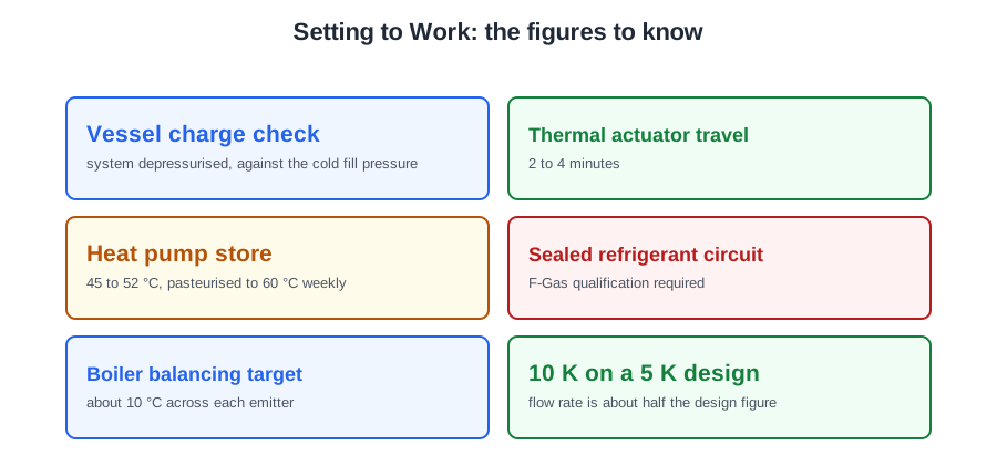
- Vessel charge check
- system depressurised, against the cold fill pressure
- Thermal actuator travel
- 2 to 4 minutes
- Heat pump store
- 45 to 52 °C, pasteurised to 60 °C weekly
- Sealed refrigerant circuit
- F-Gas qualification required
- Boiler balancing target
- about 10 °C across each emitter
- 10 K on a 5 K design
- flow rate is about half the design figure
- Index circuit lockshield
- fully open
- Probe accuracy
- about ±0.5 K — a fifth of a 5 K difference
- Temperature balancing suits
- flow deviation over ±20 per cent, at 0.75 × design drop
- Manifold
- meters indicate, return lockshields regulate
- Heat source for start-up
- 82 °C, or 15 K above design flow
- Manifold balancing
- close every lockshield first, then open the printout turns with a 4 mm key
- Underfloor heat-up
- 3 days at 20–25 °C, then 4 days at design
- Running manifold difference
- 5 to 10 °C
- Final balance
- after one week at design, furnished
- Time clock lead
- 2 to 3 hours either side of occupancy
- Set-back
- about 4 K; a good screed floor loses only 1.5 to 2 °C in 8 hours
- Two baselines
- the measured flow rate and the recorded circuit pressure
- Commissioning notice
- 5 days under a building notice, 30 days under a scheme
- ErP
- from 26 September 2015; labels banded A to G
⚠️ Where people go wrong
- Reading the vessel charge with the system pressurised. The gauge shows charge plus water pressure.
- Switching everything on at once to prove the stats. Crossed wiring looks perfectly normal.
- Deciding an actuator has failed before its travel time is up.
- Adjusting the design figure to match what the system achieves.
- Leaving the flow temperature at whatever the old boiler ran at.
- Storing at 45–52 °C without scheduling a pasteurisation cycle.
- Pasteurising only the water round the sensor. It is the whole volume.
- Signing off defrost from the settings screen. It has to be seen to drain.
- Touching the sealed refrigerant circuit without F-Gas.
- Taking readings during warm-up. Set, wait, then measure.
- Balancing by making every return the same temperature, or by pump speed.
- Throttling the index circuit. Its lockshield stays fully open.
- Temperature-balancing a 5 K design. Use flow-measuring valves.
- Balancing an unquoted system without the customer’s agreement.
- Confusing a manifold flow meter with a regulating valve, or an actuator with either.
- Setting manifold lockshields from wherever they happen to be. Close them all first.
- Balancing an empty house, and never returning once it is furnished.
- Running a screed floor on a radiator schedule, or switching it off overnight.
- Telling a customer to turn the stat up to warm a floor faster.
- Writing “left working correctly” instead of the numbers.
- Handing over a system on factory defaults, or leaving the folder on the worktop.
📝 10-Question Self-Test
Straight from the Level 3 course question bank. Click an option to see whether you got it right — the explanation appears instantly, and there is nothing to submit.
The temperature difference across flow and return is read with a thermometer on each pipe.
Tell the customer what you have found and get their agreement before you balance it. Balancing is real work that was not in the price you quoted, so it needs their say-so — but leaving a system you know is out of balance is not an option either. Winding up the pump speed to mask it just makes the near radiators noisier while the far ones stay cold.
Balancing sets each lockshield so the water gives up roughly 10 °C between the flow and return of that radiator, which is the drop it needs to emit its rated output; the UK National Annex to BS EN 12828, NA.4.3.3, puts the system design temperature drop at 10 °C unless the boiler is a special condensing or electric storage type. A 5 °C drop means the water is racing through and the far radiators will starve; 15 or 25 °C leaves the return end cold.
Start-up guidance typically gives 21–28 days for the screed to cure, and forcing the moisture out drives cracking.
With water pressure on the diaphragm the gauge reads the sum, not the charge.
Without a recorded figure, a later reading tells you nothing at all.
Service intervals and the tasks that make up a service are set by the appliance manufacturer and printed in the installation and servicing instructions; no piece of legislation lists them appliance by appliance. Part J is the tempting pick, but it deals with air supply, flues and hearths for combustion appliances, not with how often you service one.
The temperature difference is the flow rate made visible.
For a given output, the temperature difference and the flow rate are inversely related.
Without balancing, the nearest emitters take the flow and the far ones stay cold.
Going further: the lessons behind this article
This article is the public answer. Unit 333 of the Level 3 course takes the same ground to the depth the exam and the synoptic assignment ask for, in 7 lessons:
- Operational checks: the vessel, the controls and the electrical work
- Setting the controls: flow temperature, hot water and defrost
- Balancing radiators to the design temperature difference
- Starting up and balancing an underfloor manifold
- The underfloor heat-up, final balancing and set-back
- The commissioning record: what to write down and why
- Handover: the demonstration, the pack and the notices
- Central heating systems: the Unit 333 guide — every article on this unit in one place
- All PlumbMate articles — Level 1, 2 and 3
- The Level 3 course — the whole 8202-35 Diploma