A large house is to have two boilers serving four heating zones and a big cylinder. Each boiler wants a steady flow rate through its heat exchanger. Each zone wants a different one, and the zones open and close all day.
The short answer
Connect the boiler side and the system side straight together and neither gets what it needs. A low loss header settles the argument by giving each its own circuit — boilers with their own shunt pumps on one side, independently pumped zones on the other.
But be precise about what it fixes. A low loss header solves different flow rates. It does not solve a shortage of system volume, because it adds almost none. Those are two different problems with two different answers, and fitting the wrong one costs efficiency for the life of the installation.
A large house is to have two boilers serving four heating zones and a big cylinder. Each boiler wants a steady flow rate through its heat exchanger. Each zone wants a different one, and the zones open and close all day. Connect them straight together and neither side gets what it needs.
Two things go wrong when the system side dictates the flow. Too little water and the temperature difference between flow and return becomes very large, straining the heat exchanger with rapid expansion and contraction — that is thermal shock, and it destroys heat exchangers. Return water too hot and the boiler never condenses; for condensing operation the return needs to be around 55 °C or below.
A low loss header is a large-bore vessel connected across both sides, creating two circuits with hydraulic separation:
- Primary — the boilers, each with its own shunt pump, so an equal, correct velocity is maintained through every heat exchanger whatever the rest of the system does.
- Secondary — the heating zones and the cylinder, each with its own pump set to that zone's flow rate, a two-port valve, time control and room thermostat.
That is what makes a low loss header the component allowing several balanced, independently pumped circuits on a dual boiler installation. The primary circulating pump on such an installation is fitted on the heating flow. Because the header is a large, slow-moving body of water it is also the ideal place for an automatic air valve at the top and a drain point at the bottom.
Sequence control is the other half: the controller fires one boiler, then a second as load rises, and rotates which boiler leads so running hours are shared. The system is filled and kept at pressure by a pressurisation unit with its own expansion vessel rather than a filling loop. Each appliance still needs its own flue and, if condensing, its own condensate pipe to a drain or purpose-made soakaway.
What a header does not solve
This is the part that gets tested. A low loss header solves different flow rates on either side. It does not solve a shortage of system volume, because it adds almost none. On a low temperature system, manufacturers commonly ask for around 20 litres of system volume per kW so the appliance can run without short cycling and has something to draw on during a defrost — and a small modern house may simply not contain it.
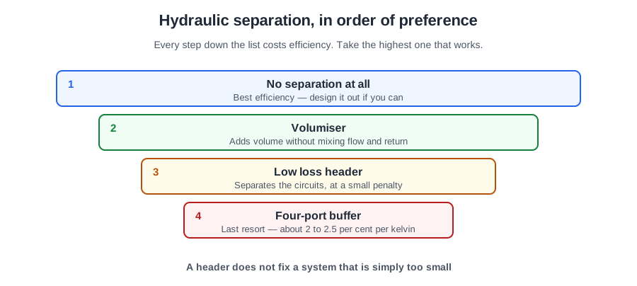
So there is an order of preference, from least intervention to most:
- None, where the system already has the volume and can maintain minimum flow. Leaving one circuit without a TRV, usually the hall, or fitting an automatic bypass, is often enough.
- A volumiser — a two-port buffer in series on the return, where only volume is short. One pump still serves both sides, so it does not separate the circuits and does not carry the efficiency penalty.
- A low loss header, where only the flow rates differ.
- A four-port buffer, only where both problems exist at once.
The last one costs something permanent. Mixing inside a four-port buffer means the system side runs cooler than the boiler side, so the heat source has to run hotter to compensate — at roughly 2 to 2.5 per cent of efficiency for every kelvin, for the life of the installation. Separate only as much as the system actually needs.
🔢 The numbers worth memorising
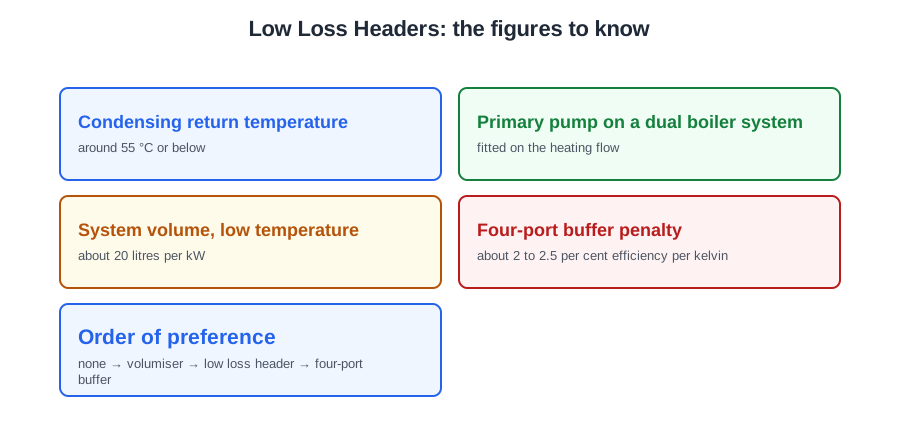
- Condensing return temperature
- around 55 °C or below
- Primary pump on a dual boiler system
- fitted on the heating flow
- System volume, low temperature
- about 20 litres per kW
- Four-port buffer penalty
- about 2 to 2.5 per cent efficiency per kelvin
- Order of preference
- none → volumiser → low loss header → four-port buffer
⚠️ Where people go wrong
- Fitting a low loss header to fix a shortage of system volume. It adds almost none — that is a volumiser.
- Fitting a four-port buffer by default. Both problems have to be present to justify the permanent efficiency cost.
- Letting the system side dictate the flow through the boiler. Too little water is thermal shock.
- Returning water too hot to a condensing appliance. It simply never condenses.
- Sharing one pump across a header. Each boiler needs its shunt pump and each zone its own.
- Filling a multiple boiler installation with a filling loop. It gets a pressurisation unit with its own vessel.
📝 8-Question Self-Test
Straight from the Level 3 course question bank. Click an option to see whether you got it right — the explanation appears instantly, and there is nothing to submit.
A low loss header is a large-bore vessel connected across both sides of the system, giving hydraulic separation. The boilers keep their own shunt pumps and their own flow rates, and each heating zone and the cylinder get a pump set to what that circuit needs, so all of them can be balanced. A twin-boiler sequencer is tempting, but it only decides which boiler fires and when.
A low loss header splits the system in two and the pump you are asked about belongs on the boiler side. CIBSE Guide B1 clause 1.8.6.1 describes a single header into which the primary flow and return headers and all the secondary circuits connect, and says the primary circuit carries a common circulation pump, or one pump per heat generator. So the primary pump moves water round the heat generators and the header, and nothing else. The pump on the heating flow beyond the header is a secondary or load pump, and calling it the primary one is the mistake this question is built to catch. The last option is worth naming as well: the header decouples the two circuits hydraulically so that one pump does not fight the other, but it does not make pump position arbitrary. Each circuit still needs its own pump, sized for its own resistance, and the header only works while the flow through it stays low enough that the pressure along its length is very nearly constant.
A heat interface unit is the packaged plate heat exchanger, valves, controls and heat meter that separates each flat's system from the district network.
No separation where the system has the volume and can keep the minimum flow. A volumiser if only volume is short, a header if only flow rates differ, and a four-port buffer only where both problems exist.
Mixing in the vessel means the emitters see cooler water, so the heat pump must run hotter to compensate, and its efficiency falls as the temperature it delivers rises. That penalty is paid for the life of the installation.
Typically the hall, whose temperature is set by the room thermostat. An automatic bypass and less aggressive zoning do the same job.
Fitted in series on the return, so one pump still serves both sides. It does not carry the efficiency penalty of full separation, which is why it is preferred where only volume is short.
Heat pump flow and return on one side, system on the other, each with its own pump. It adds almost no volume, so a volumiser or a buffer is needed where that is what is short.
Going further: the lessons behind this article
This article is the public answer. Unit 333 of the Level 3 course takes the same ground to the depth the exam and the synoptic assignment ask for, in 1 lessons:
- Multiple boilers, low loss headers and hydraulic separation
- Central heating systems: the Unit 333 guide — every article on this unit in one place
- All PlumbMate articles — Level 1, 2 and 3
- The Level 3 course — the whole 8202-35 Diploma