A sealed system discharges out of the safety valve every evening when the heating has been on an hour, and by morning the gauge has fallen back. The boiler is fine and there is no leak.
The short answer
The system has nowhere to put its expansion. A safety valve on a healthy system should never operate, and when it does, the cause is almost always one of three things: a ruptured diaphragm, a lost air charge, or a filling loop left connected and passing.
Learn the sealed system as four components with numbers attached — vessel, safety valve, pressure gauge, filling loop — and the fault-finding follows from the design.
The expansion vessel
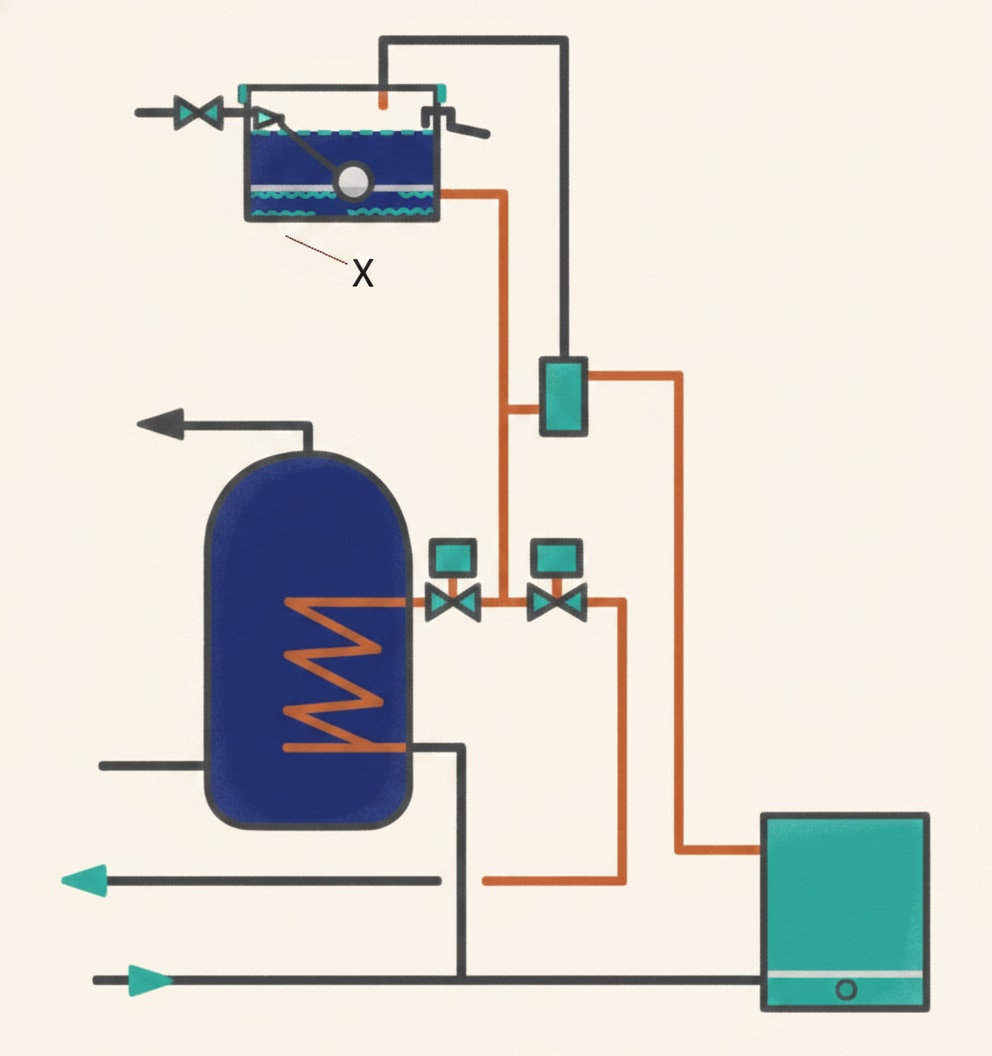
A sealed system has no feed and expansion cistern and no open vent. The vessel takes their place: a steel cylinder divided by a diaphragm, normally neoprene rubber. One end carries a schrader air valve — the same fitting as a tyre valve; the other a ½ inch male BSP thread to the system.
Air is pumped in behind the diaphragm to about 1 bar, pushing it across so it almost fills the vessel. When the system is filled to about 1 bar, water pushes the diaphragm back slightly and the pressures balance. As the water heats and expands it pushes further and compresses the air, so system pressure rises; on cooling, the air pushes the water back out.
Where it goes
Fit the vessel on the return pipework wherever possible. The return is generally about 20 °C cooler than the flow, which puts far less temperature stress on the diaphragm. BS EN 12828 clause 4.6.2.4 says the same: positioned so the maximum allowable membrane temperature cannot be exceeded, preferably on the return pipe or at the point of lowest system temperature, with the manufacturer's instructions paramount.
If the flow is unavoidable, it must go on the suction (negative) side of the circulating pump, so the pump cannot force the pressure up and open the safety valve.
Two more rules from the same clause. There must be no shut-off device between the expansion vessel and the heat generator — an engineer's lockable isolating valve may be considered for maintenance, but not an ordinary valve anyone can close. And the vessel must be in a frost protected room or otherwise protected against freezing.
Charge pressure
The UK National Annex (NA.4.7.1.2): the charge pressure should be not less than the static head pressure at the centre of the vessel. Static head is about 0.1 bar per metre, so a system with 10 m from the vessel to the highest point needs at least 1 bar.
Check the charge with a tyre-type gauge with the system side drained or depressurised, and top up with a foot pump through the schrader valve. The same annex defines the practical acceptance volume: what the vessel will take when the gauge pressure has risen to 0.35 bar below the safety valve setting.
Sizing it
Size it to the boiler manufacturer's instructions. Where they are not available, use Table NA.2 of BS EN 12828, entering with the total water content, the safety valve setting, and the charge and initial system pressure. For a full calculation, BS 7074-1 gives the method.
| System water content | 3 bar valve, 0.5 bar charge | 3 bar valve, 1.0 bar charge | 3 bar valve, 1.5 bar charge |
|---|---|---|---|
| 50 L | 4.2 L | 5.4 L | 7.8 L |
| 100 L | 8.3 L | 10.9 L | 15.6 L |
| 150 L | 12.5 L | 16.3 L | 23.4 L |
| Factor per litre | 0.0833 | 0.109 | 0.156 |
So a 100 litre system with a 3 bar safety valve charged to 1 bar needs a 10.9 litre vessel. Raising the charge pressure raises the vessel size, which is why an unnecessarily high charge is expensive.
Where the boiler has an integral vessel, check its capacity actually covers the system — the annex warns that an additional vessel may be required.
The safety valve
A sealed system installed with the safety valve tucked behind the cylinder, teed off the return with an isolating valve before it, and its discharge run in 10 mm pipe up over a joist and down to a gully. Every one of those decisions is wrong, and the standard says so.
Clause 4.6.2.2.1 requires that each heat generator is served by at least one safety valve, and where the manufacturer has not fitted one, it goes on the system as near as possible to the heat generator. Then the detail:
- Minimum size DN 15.
- It must open at a pressure not exceeding the maximum design pressure, and prevent the maximum operating pressure being exceeded by more than 10 per cent.
- The pressure drop of the inlet pipe must not exceed 3 per cent, and of the discharge pipe 10 per cent, of the set pressure — which is why the discharge is run full bore and short.
- Installed in an accessible location, in the immediate vicinity of the heat generator flow pipe.
- No isolation valve between the heat generator and the safety valve.
- It must discharge safely, by a relief pipe to a drain in a safe location.
The UK National Annex (NA.4.7.1.1.1) adds what a domestic valve must be: non-adjustable, spring-loaded and pre-set to lift at a gauge pressure not exceeding 3 bar, with a manual testing device, seating material that will not stick closed and reseals effectively, and provision for a full-bore discharge pipe.
Run the discharge in the full bore of the valve outlet, with a continuous fall, terminating outside in a safe and visible position. The water leaving it may be well over 80 °C. Visible matters: a valve discharging quietly into a drain nobody looks at will waste water and destroy the inhibitor for months.
At service, test it by twisting the top and holding it open for 30 seconds, then check it closes completely with no drips. A valve that will not reseal is replaced, not repaired.
The pressure gauge
Clause 4.7.2 requires at least one pressure gauge with a measuring range at least 50 per cent higher than the maximum operating pressure. On a system protected at 3 bar, that means a gauge reading to at least 4.5 bar. The same clause requires at least one temperature measuring device with a range at least 20 per cent above the maximum operating temperature, mounted in the flow pipe. Open vented systems do not need either unless the appliance instructions say so.
The gauge earns its place twice. It is how you set the correct cold fill pressure. And afterwards it is a warning: a pressure that falls inexplicably points to an undetected leak; one that rises points to a failed expansion vessel or a passing filling loop. Gauges are notorious for going out of calibration, so one that disagrees with a second gets replaced.
The filling loop and backflow
A boiler service turns up a filling loop still connected, both valves cracked open, and a pressure of 2.4 bar cold. The customer has been topping it up for two years because the safety valve keeps discharging. It is a water regulations offence and a system fault at the same time.
The connection is a cross connection between two different waters. The cold main is fluid category 1, wholesome water supplied by the undertaker; the heating system is fluid category 3. Under Schedule 1 of the Water Regulations, category 3 is fluid representing a slight health hazard because of the concentration of substances of low toxicity, including any fluid containing ethylene glycol or similar chemical additives — exactly what a dosed heating system contains.
Schedule 2 paragraph 15 requires an adequate device for preventing backflow, appropriate to the highest applicable fluid category downstream. Paragraph 14 adds that no supply pipe shall be connected so it can convey a fluid that is not wholesome water.
A filling loop contains, in order from the main: a service or isolation valve, a verifiable double check valve (type EC), the flexible hose, and a second isolation valve on the heating side. A type ED is the non-verifiable equivalent.
Backflow protection is achieved in two ways together. The double check valve guards against backflow while the loop is connected. And the loop must be disconnected after filling, so that no connection remains — the physical break that makes backflow impossible.
The loop goes on the return pipe close to the expansion vessel, and is often supplied as part of the vessel assembly. BS EN 12828 Annex D puts the fill position between the expansion vessel connection and the pump inlet.
Where a permanent connection is wanted, a type CA disconnection device with a pressure reducing valve can replace a removable loop on a domestic system, because that water is category 3. On a commercial system a CA device is only acceptable where the boiler is rated up to 45 kW; over 45 kW the water is fluid category 4, and a permanent connection then needs a type BA RPZ valve. The CA device has an integral tundish; in normal use it should not discharge, though it may pass a little if the supply pressure falls below 0.5 bar or 11 per cent of the downstream pressure.
Charging the system
Before you open anything: all radiator valves and air release valves closed, all drain-off valves closed, all motorised valves manually opened, thermostats off, and the pump out with a temporary pipe in its place.
Then fill in stages, so a leak is found stage by stage. Open the downstairs radiators first, working back towards the boiler, then the upstairs circuit from the furthest radiator back. Vent the index radiator — on a sealed system the pressure drops as you vent, so top up again.
Dose the inhibitor via a radiator: roughly 1 litre for a ten radiator system of about 100 litres, counting a double panel radiator as two.
Set the cold fill pressure, usually about 1 bar, with the system cold and stable. Do not overfill — an overfilled system simply pushes the safety valve open once it is hot.
Then close both loop valves and disconnect the loop. Left connected with a worn service valve, it feeds the main into the system, the pressure climbs and the safety valve discharges.
🔢 The numbers worth memorising
- Vessel position
- return, or flow only on the suction side of the pump
- Return temperature
- about 20 °C cooler than the flow
- Charge pressure
- not less than the static head — about 0.1 bar per metre
- Acceptance volume
- at 0.35 bar below the safety valve setting
- 100 L system, 3 bar valve, 1 bar charge
- 10.9 litre vessel
- Safety valve
- DN 15 minimum, non-adjustable, spring-loaded, not over 3 bar
- Overpressure limit
- no more than 10 per cent above maximum operating pressure
- Pipe pressure drops
- inlet 3 per cent, discharge 10 per cent of set pressure
- Valve test
- hold open 30 seconds, then closes with no drips
- Pressure gauge range
- at least 50 per cent above maximum operating pressure
- Temperature device
- at least 20 per cent above, in the flow pipe
- Fluid categories
- main category 1, heating system category 3
- Loop protection
- verifiable double check valve (EC) while coupled, then disconnected, so no connection remains
- CA device limit
- commercial boilers up to 45 kW; above, category 4 and a type BA RPZ
- Inhibitor dose
- about 1 litre per ten radiator, 100 litre system
- Cold fill pressure
- about 1 bar
⚠️ Where people go wrong
- Fitting the vessel on the flow, on the pump’s discharge side.
- Putting an ordinary isolating valve between the vessel and the boiler.
- Reading the charge pressure with the system still under pressure.
- Raising the charge pressure “to be safe”. It raises the vessel size you need.
- Assuming a boiler’s integral vessel covers the system. Check the water content.
- Fitting an isolating valve between the boiler and the safety valve.
- Running the discharge in reduced bore, or up over a joist.
- Terminating a discharge somewhere nobody looks. It must be visible.
- Repairing a safety valve that will not reseal. Replace it.
- Fitting a 3 bar gauge to a 3 bar system. It reads to at least 4.5 bar.
- Leaving the filling loop connected. Category 3 water against a category 1 main.
- Relying on the double check valve alone. Disconnecting the loop is half the protection.
- Filling with the pump in, or with the motorised valves closed.
- Overfilling. The safety valve simply opens once it is hot.
📝 9-Question Self-Test
Straight from the Level 3 course question bank. Click an option to see whether you got it right — the explanation appears instantly, and there is nothing to submit.
Clause 4.6.2.4 states there shall be no shut-off device positioned between the expansion vessel and the heat generator. A valve anyone can close leaves the system with nowhere to put its expansion, so the safety valve becomes the only relief. The same clause allows consideration of an engineer's lockable isolating valve for maintenance purposes, which is not the same thing as an ordinary lever valve, and it also requires the vessel to be in a frost protected room or otherwise protected against freezing.
The UK National Annex to BS EN 12828, NA.4.7.1.2, says the vessel charge pressure should be not less than the static head pressure at the centre of the expansion vessel. Static head is about 0.1 bar for every metre of height, so 10 m gives 1 bar. Check it at the Schrader valve with the system side depressurised. 3 bar is the maximum a domestic safety valve may be set to lift at, not a charge pressure.
NA.4.7.1.2 says vessel sizing should be in accordance with the boiler manufacturer's instructions, and where these are not available Table NA.2 should be used. For a 3 bar safety valve setting with a 1 bar charge and initial system pressure the multiplying factor is 0.109 per litre of system water, so 100 litres needs 10.9 litres of vessel. 8.3 litres is the answer for a 0.5 bar charge; raising the charge pressure raises the vessel size needed.
Clause 4.6.2.2.1 requires safety valves to have a minimum size of DN 15 and to be installed in an accessible location in the immediate vicinity of the heat generator flow pipe. Accessible matters because the valve has to be operated by its manual test device at every service. Putting it on the return by the vessel takes it away from the point the standard names.
Clause 4.6.2.2.1 requires safety valves to discharge safely, by a relief pipe discharging to a drain in a safe location, and limits the pressure drop of the discharge pipe to 10 per cent of the set pressure. Reducing the bore or lifting the pipe over a joist would exceed that. The UK National Annex NA.4.7.1.1.1 requires provision for connecting a full-bore discharge pipe. Visible matters too: water leaving the valve can be well above 80 °C, so it must not discharge where anyone can be scalded, and a valve discharging into a hidden drain will waste water and inhibitor for months before anyone notices.
BS EN 12828 clause 4.7.2 requires heating systems to be served by at least one pressure gauge with a measuring range of at least 50 per cent higher than the maximum operating pressure. That is not the same figure as the valve setting: clause 4.6.2.2.1 has the valve stop the maximum operating pressure being exceeded by more than 10 per cent, and NA.4.7.1.2 works 0.35 bar below the setting, which puts it near 2.65 bar here. Fifty per cent above that is about 4 bar, and 4.5 bar is the smallest range offered that covers it. A gauge stopping at the valve setting cannot show how far past it the pressure has gone.
Schedule 2 paragraph 15 requires every water system to contain an adequate device for preventing backflow, and paragraph 15(3) requires the device used to be appropriate to the highest applicable fluid category to which the fitting is subject downstream. A heating primary is fluid category 3, and the double check valve is the mechanical device for category 3; the verifiable type EC can be tested in place. A single check valve only protects to category 2, and an RPZ valve is the category 4 device, needed on a commercial system above 45 kW rather than on a domestic filling loop.
The double check valve protects the connection only while it is made, and it can pass with age or grit. Taking the loop off removes the cross connection between the category 1 main and the category 3 heating water altogether, which is what Schedule 2 paragraph 15 is aiming at. A permanent connection is possible, but it then needs a type CA disconnection device rather than a hose. There is a system reason too: a loop left connected with a worn service valve slowly feeds the main into the system until the safety valve discharges.
The cold fill pressure has to leave room for the water to expand. The UK National Annex NA.4.7.1.2 sizes the vessel on the practical acceptance volume, what it will accept when the gauge pressure rises to 0.35 bar less than the safety valve setting, so the cold pressure has to start where the sizing assumed, normally about 1 bar or the figure in the boiler manufacturer's instructions. Filled to 1.8 bar cold, the system will reach the setting as soon as it is hot and discharge water and inhibitor every day. Raising the vessel charge to match an overfilled system creates no extra expansion space at all.
Going further: the lessons behind this article
This article is the public answer. Unit 333 of the Level 3 course takes the same ground to the depth the exam and the synoptic assignment ask for, in 3 lessons:
- The expansion vessel: position, charge pressure and size
- The safety valve and the pressure gauge
- The filling loop, backflow protection and the cold fill pressure
- Central heating systems: the Unit 333 guide — every article on this unit in one place
- All PlumbMate articles — Level 1, 2 and 3
- The Level 3 course — the whole 8202-35 Diploma